
Accurate Real-time Complex Cutting in Finite Element Modeling
Tong Xin, Pieran Marris, Ana Mihut, Gary Ushaw and Graham Morgan
School of Computing, Newcastle University, Urban Sciences Building, 1 Science Square, Science Central,
Newcastle upon Tyne, U.K.
Keywords:
Cloth Simulation, Cutting, FEM, Real Time.
Abstract:
This paper presents a real-time method for enacting accurate cutting of thin materials while retaining the
physical accuracy of the underlying deformable material model. Our primary contribution is to offer a flexible
real-time solution that can allow accurate cuts, re-cuts, curved cuts, sectioning (cutting out) on a deformable
FEM model. Further contributions include improved handling of mesh element resizing after cutting for
increasing material stability while balancing such resizing against real-time requirements. In this manner, we
can represent precise cut incision (which may be curved or irregular) by subdividing mesh elements locally (at
the cut point) while negating inappropriate (ill-shaped) elements with real-time level computational overhead
and so avoiding modeling instabilities efficiently. We present the results of our solution that show the accuracy
of the cutting method and illustrate timings for our optimised approach demonstrating its real-time qualities.
1 INTRODUCTION
As real-time simulations have provided models rep-
resenting increased visual realism, matching this with
physical interaction realism is required. One such in-
teraction property that has received significant inter-
est is that of cutting; acting cuts into simulated ar-
tifacts in real-time and having the results persist. It
has been explored more in those applied areas of re-
search that favor accuracy of precision and material
behavior (e.g., simulated surgery) and less so in those
favors aesthetics over interaction (e.g., video games).
It brings about a balance between physical proper-
ties and aesthetic appearance in cutting. To achieve
precision and accuracy while maintaining appropriate
(believable) interaction requires a material model of
advanced features that impact negatively on overall
real-time performance.
The finite element method (FEM) is a com-
mon choice for constructing accurate models of de-
formable material behavior. The model has properties
that allow accurate inspection of stress and other re-
lated parameters to determine the potential real-world
behavior. FEM is computationally more expensive
to achieve than its counterparts that afford visually
pleasing simulations at the expense of physical ac-
curacy (e.g., mass-spring). However, to achieve re-
alism in cutting and leave a post-cut model that be-
haves as expected in the real world then FEM is a
clear choice. However, difficulty arises in reorganiz-
ing the mesh of the FEM (the representation of the
surface area) to ensure accurate cut depiction (the cut
is where one desires) and resultant models still exhibit
appropriate physical properties (no irregular behavior
is introduced due to cuts). It requires a suitable algo-
rithmic solution to ensure the reorganization, and pos-
sibly introduction or removal, of the elements (usu-
ally triangles) that constitute the mesh representing
the model under dissection. Presenting algorithmic
solutions that are engineered to work in real-time is
the main focus of this paper.
Achieving accurate cut incisions does require el-
ements to be altered or introduced. If a cut is to be
presented exactly where a user needs, then elements
must be reconstituted around this area, usually, it re-
quires introduce additional mesh elements. However,
achieving accurate cuts while making appropriately
shaped elements is a non-trivial problem at the heart
of a real-time FEM cutting technique. Ill-shaped ele-
ments relate to the inner working of the FEM; each el-
ement represents a unit of deformability that is solved
to present an overall ”shape” of the material model.
As discretization is required as a step to attaining a
practical solution, ill-shaped objects can inject signif-
icant errors in the cumulative mathematical calcula-
tions. It is compounded in real-time solutions where
equation solvers accomplish a solution within a time
boundary. A time boundary too low would provide in-
sufficient time to achieve the desired mathematical ac-
curacy that, ultimately, will cause the material model
Xin, T., Marris, P., Mihut, A., Ushaw, G. and Morgan, G.
Accurate Real-time Complex Cutting in Finite Element Modeling.
DOI: 10.5220/0006542801830190
In Proceedings of the 13th International Joint Conference on Computer Vision, Imaging and Computer Graphics Theory and Applications (VISIGRAPP 2018) - Volume 1: GRAPP, pages
183-190
ISBN: 978-989-758-287-5
Copyright © 2018 by SCITEPRESS – Science and Technology Publications, Lda. All rights reserved
183

to fail.
The more complicated and flexible a material
model is regarding cutting the more compounded the
difficulty of ensuring real-time and physical accu-
racy. That is certainly true when allowing re-cutting
as already altered and newly introduced mesh ele-
ments must be re-altered and managed while main-
taining real-time behavioral properties. As mesh ele-
ments growing (more cuttings) so the computational
expense increases and the possibility of ill-shaped ele-
ments also increases; this is when existing approaches
tend to have the greatest difficulty, and many do not
attempt re-cutting, especially in real-time scenarios.
In this paper, we continue the line of research
into the cutting of material models using FEM. How-
ever, we present a general solution applicable to ad-
vanced material models that can be simulated in real-
time. We present solutions to re-meshing of the mate-
rial model after cutting that minimizes ill-shaped el-
ements while accurately reflecting the exact position
of the desired cut. Our novel approach provides con-
vincing cuts that can be straight or curved, appear ex-
actly where directed, allows re-cutting and the abil-
ity to cut-out (resulting in multiple FEMs) and do so
while maintaining the physical properties of the cloth
model itself.
2 BACKGROUND AND RELATED
WORKS
Our primary focus is to generate aesthetically pleas-
ing cuts to dynamic, responsive, material models
while retaining accurate physics behavior in real-
time. The cutting of deformable material has been
an active area of research for many years (Wu et al.,
2015). In this section we provide a broad discus-
sion of techniques that use a variety of models, how-
ever, for brevity we only afford additional debate for
those works that are focussed on (but not necessarily
achieved together): (1) accurate cutting; (2) FEM; (3)
real-time; (4) re-meshing.
2.1 Cutting
In mesh-based cutting techniques, non-progressive
approaches have advantages by which computational
overhead can be minimized using mesh subdivision
determined as a whole, and present a cut at any de-
sired point (Pietroni et al., 2009; Steinemann et al.,
2006). An alternative approach is to use XFEM,
where the cut can be described separately as a func-
tion on top of the higher order model (Kaufmann
et al., 2009). The latest work in this area is com-
pelling, allowing cutting of 3D objects (Koschier
et al., 2017). The placement of the cut can be very ac-
curate. However, the cut edge can hardly inherit fun-
damental physics with the approximate enrichment
basis functions.
Besides the persistence of cuts, the ability to re-cut
areas must be considered carefully. As the topology
of the mesh could be partially split numerous times
before the current cut, care must be taken to assure
the subdivision of the start and end elements is prop-
erly handled. The meshless model approach proposed
by (Nesme et al., 2009) and polygon model (Sifakis
et al., 2007) present abilities to re-cut, but such mod-
els are unlikely to find favor in real-time simulations
that leave the underlying mesh altered.
2.2 Topology
Due to its relatively simple construction and con-
vincing behavior the spring-based system (Baraff and
Witkin, 1998) has been widely used for material
modeling cutting (Cotin et al., 2000; Souza et al.,
2014). Unfortunately, the model relies on the the
springs connectivity and once the pattern is altered,
behavior is not convincing. FEM employee dynam-
ically reconstructs each of the element interactions
based on the shape function, in this manner force
is enacted across elements rather than independently
across springs (Cakir et al., 2009). FEM then is ex-
ploited to provide more physically accurate deforma-
tions (Yeung et al., 2016).
Nonlinear FEM approaches employee nonlinear
solver to handle deformation, while they are computa-
tionally more expensive than linear FEM. This can be
largely mitigated with introducing co-rotational FEM
(Georgii and Westermann, 2008). It adopts linear
stress/strain solver on each element, and pre-compute
a single stiffness matrix which is then simply trans-
formed into the current configuration. It provides a
fast FEM simulation with only a negligible overhead
compared to mass-spring systems. Therefore it has
been used in cutting simulations (Courtecuisse et al.,
2010; Turkiyyah et al., 2011).
2.3 Subdivision
Subdivision algorithm provides an opportunity for re-
cutting the same area on material models. Edge split-
ting changes the mesh connectivity (Souza et al.,
2014; Yeung et al., 2016), whereas other methods
such as vertex-snapping merely move the nodes to
along cut path (Serby et al., 2001). Although it pro-
vides pleasing results, on a coarse mesh it can often
GRAPP 2018 - International Conference on Computer Graphics Theory and Applications
184
lead to jarring effects. For this reason, we handle edge
splitting using current dynamic subdivision (Bielser
et al., 2004) with the non-uniform subdivision. How-
ever, other edge splitting methods often result in for-
matting ill-shaped elements.
Adaptive subdivision schemes verify the level of
subdivision depending on the force intensity acting on
the mesh so that can produce a high-quality mesh in
physics-based deformation (Bender and Deul, 2013;
Narain et al., 2013; Koh et al., 2014), tearing (Pfaff
et al., 2014) and force-based cutting (Seiler et al.,
2011). These methods enforcing uniform subdivision
avoiding ill-shaped elements. However, this also in-
curs a substantial computational overhead and thus in
many cases a coarse subdivision level is defined.
The Delaunay approach has been used (Nienhuys
and van der Stappen, 2004; Busaryev et al., 2013)
to limiting ill-shaped elements. A further issue is
the problem of computational complexity, although
vastly optimized, Delaunay triangulation is still de-
pendent on the problem size and can be computation-
ally expensive.
3 THEORETICAL BACKGROUND
Mesh quality is a crucial factor in FEM-based cutting
techniques for maintaining numerical stability and ro-
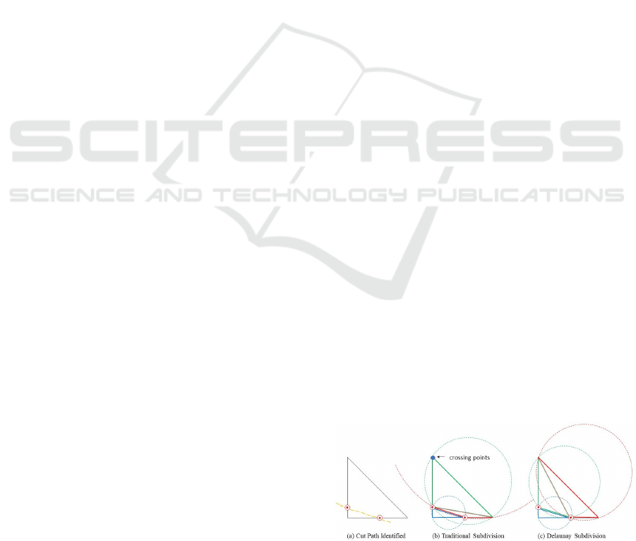
bustness of the simulation. The Delaunay refinement
scheme is a well-established technique for maintain-
ing mesh quality (Bowyer, 1981). It is achieved by
ensuring that no nodes are created within the circum-
circle of existing triangles, as illustrated in Figure 1.
The effect of this is to ensure that the minimum angle
of created triangles is maximized, thereby improving
mesh quality.
The Bowyer-Watson algorithm reduces computa-
tion cost by eliminating the need for complex topo-
logical validity checks (Rebay, 1993). The approach
incrementally inserts one node at a time, and then lo-
cally validates the triangulation of a subset of the de-
sired points. It can take O(N × log N) operations to
triangulate N points. With the consideration of lim-
ited computation cost in real-time applications, we
adopt the Bowyer-Watson algorithm to generate ini-
tial Delaunay triangulation.
4 IMPLEMENTATION
Our approach combines a Delaunay-based refinement
technique (Bowyer-Watson algoritm) on co-rotational
finite element modeling. It ensures that the higher
computational cost of a subdivided mesh is focused
on the areas of material closest to the simulated cut
while maintaining the quality of the modified mesh.
Furthermore, we apply a local split optimization pro-
cess to handle the ill-shaped triangles.
4.1 Mesh Cutting
When operating subdivision method as the number of
modification increases, there is a necessary trade-off
of fidelity of simulation and mesh quality. Conse-
quently, a technique which focuses on both the sub-
division of elements in the area of the mesh most af-
fected by the cut and the quality of generated mesh
elements can lead to an optimal solution.
4.1.1 Locality of the Cut
The first step in simulating a cut to the material is to
identify the triangles of the mesh that are affected.
The process of Delaunay triangulation and incision
generation will take place in the local coordinate
space of the material mesh with no deformation due
to external forces. However, the causes such as col-
lisions takes place in world space, where the material
is in a deformed state.
For our simulation, a mouse is used to identify the
location of an incision in the world space. The po-
sition of the mouse in the 3D world space is trans-
lated to an un-deformed local space for the material
mesh. The path of the incision is generated from a
cubic Bezier curve which requires four control points
(four mouse clicks).
Intersection detection will operate between the cut
path and each edge of triangles of the mesh. Triangles
with one or two line intersections will then be consid-
ered for generating initial Delaunay triangulation in
the next stage of the algorithm. New points will be
inserted at the exact place where the cut crosses the
triangle edge.
4.1.2 Initial Delaunay Triangulation Generation
An example of traditional and Delaunay subdivision
is shown in Figure 1. In the case of the traditional
Figure 1: Delaunay generation principle.
subdivision, an ill-shaped triangle has been generated,
Accurate Real-time Complex Cutting in Finite Element Modeling
185
and there are nodes of other triangles within its cir-
cumcircle. The right diagram illustrates the Delaunay
triangulation in which no circumcircle of any triangle
in the triangulation includes nodes from other trian-
gles.
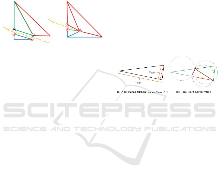
The two instances of triangle cut types are illus-
trated in Figure 2. A new node is created on any in-
Figure 2: An example triangle with two intersection points
(left), and an example triangle with one intersection point
(right).
tersected edges at the position of intersection (i.e. one
for each side of the cut at each intersection to open
the cut incision. The Bowyer-Watson algorithm then
regenerates the original triangle shape made up from
constituent triangles with the three original points and
new points. Consequently, the original triangle is sub-
divided into two or three constituent triangles. Espe-
cially, when a cut is terminate inside the triangle the
original triangle will be replaced by four small trian-
gles as shown on the right of figure 2, and the incision
will also terminate inside the triangle. In the case of
two intersection points, one of the triangles is sepa-
rated by duplicated nodes.
Any ill-shaped triangles generated in this step will
be recognized and grouped for the optimization oper-
ation.
To generate arbitrary incisions (e.g. intersected
cuts), the connectivity between the affected triangle
and its neighbors is considered when opening cut in-
cision. After recognizing an intersected edge, our
method identifies whether there is another triangle
that shares that edge. In that case, the new point and
its duplicate are shared by the affected triangle and its
neighbor.
4.1.3 Localized Optimization
In the linear finite element method, the computa-
tional speed can be reduced by inefficient elements
in the mesh. Consequently, optimal mesh generation
and modification are required to produce high-quality
mesh elements. This issue has been specifically iden-
tified in triangular meshes (Shewchuk, 2002) where
irregular sizes or shapes of triangles can have a detri-
mental effect on computation time. While the Delau-
nay algorithm can maximize the minimum angle of
all triangles in the triangulation, this does not guar-
antee that no ill-shaped triangles will be generated.
To address this problem, we introduce local split opti-
mization to increase the quality of the modified mesh.
We identify the aspect ratio as the parameter to
efficiently evaluate our generated triangles. For trian-
gular meshes, aspect ratio is defined as:
AR = l
max
/a
max
(1)
where l
max
is the length of the maximal edge, and a
max
is the height measured from this edge. The approxi-
mate minimum possible aspect ratio for the original
triangles in the mesh is 2. In our local split opti-
mization algorithm, newly generated triangles whose
aspect ratio is more than 3 will be re-triangulated as
shown in the right of Figure 3. The steps of our opti-
Figure 3: An example of the localized optimization.
mization operation are:
• The two longest edges are selected first;
• New points are inserted at the mid-point of the
selected edges;
• Any ill-shaped triangle (as defined by aspect ratio)
is regenerated by the Delaunay algorithm;
The introduction of new points necessitates the
subdivision of the triangles that are directly adjacent
to the new points (referred to as the 1-ring triangles).
During the subdivision step, if an edge is subdivided,
but its neighbor is not, a discontinuity can be created
(as illustrated by the shaded section in Figure 4) in
the form of a crack. Avoiding this cracking of the
mesh, the neighboring 1-ring triangle is also subdi-
vided with the new points, replacing the triangle with
two constituent triangles (as shown in the right of the
figure). Note that only one of the 1-ring triangles re-
quires this subdivision (rather than all of them as in
the more generalized subdivision methods). Further-
more, if there is any ill-shaped triangle created during
this step, our optimization process will keep operating
until the triangulation is under the acceptable level.
4.2 Topological Modification
Employing a linear elasticity model with an implicit
integration scheme allows us to generate a fast and
GRAPP 2018 - International Conference on Computer Graphics Theory and Applications
186
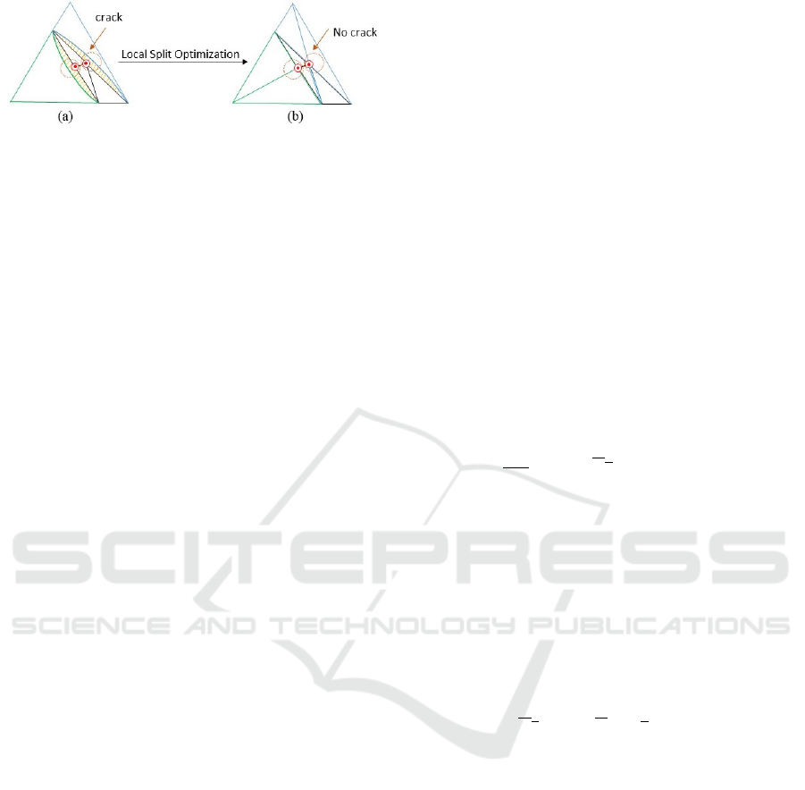
Figure 4: A crack appears when its neighboring triangle has
been subdivided (a), 1-ring neighbors of subdivided trian-
gles are split as well (b).
stable simulation. However the approach can also re-
sult in unrealistic or unstable effects when large defor-
mations are needed. To resolve this issue, we use co-
rotated finite element modeling (Felippa and Haugen,
2005; Georgii and Westermann, 2008), which extract
the non-linear part of the current deformation before
computing the forces.
As cutting of a mesh necessitates disconnecting
parts of that mesh, a topological modification is re-
quired. Changing any element of the global matri-
ces invalidates any previous factorization, necessitat-
ing a refactorization of the matrices. Rather than re-
constructing the global matrix in each time step, we
incrementally update the global matrix from the cur-
rent state in two steps: index replacement and element
addition.
4.2.1 Index Replacement
In contrast to current methods, we change the vertex
indices of all intersecting faces so that the contribu-
tions of the original elements are not removed but re-
placed in the global stiffness matrix K. For instance,
if in time (i) the cut path passes through the element
S
e
two vertex indices of the element are replaced by
the indices of new points to fill in one side of the in-
cision. In the next step (i + 1) the element stiffness
matrix K
e
must be updated. The initial area A
e
will
be calculated from the new vertex positions. As dis-
crepancies in vertex indices can lead to computational
inefficiency, we mitigate this effect by changing the
vertex indices in this step.
4.2.2 Element Addition
After the index replacement step, new vertices are cre-
ated to prepare for element modifications, so the di-
mension of matrices will be increased to accommo-
date the new vertices. Rather than reconstructing the
global matrix in each time step, we incrementally up-
date the global matrices. For instance, the stiffness
matrix K is updated to:
K
0
= K
0
+
m
∑
i=1
G
i
K
I
G
T
i
(2)
where K
0
and K
0
represent the current stiffness matrix
in this time step i and the updated stiffness matrix in
next time step i + 1, m is the number of new elements,
K
i
,G
i
and G
T
i
are the matrices which map the rows
and the columns of the new element metrics to the
global matrix. The mass and damping matrices must
also be updated in an equivalent way.
The new vertices introduced in the subdivision of
the cut triangle, and the affected neighboring trian-
gles, are each added to the global matrices in this
manner. This dynamic approach, incorporating each
new vertex into the index list incrementally (in two
steps as described), is more computationally efficient
than recalculating the global matrix for the entire
mesh.
4.3 Time Integration
We employ an implicit time-based solver to simulate
the evolution of the visco-elastic deformable surface
model.
M
d
2
x
dt
2
= Kx + Kx +
e
Kx + f
(v)
+ f
ext
(3)
Where x is a matrix containing each of the n vertices
in the model. For the time step t when the cutting
path is instigated, computation is completed by the
following steps:
• Compute the rotations R
e
for each triangle.
• Update the stiffness matrix K with the two steps
described in section 4.2, assemble the global ma-
trix
e
K (rotate the result of multiplication back to
3D space), and compute the viscous bend force
f
(v)
with velocity v.
• Compute Kx, where K and x stand for the stiffness
matrix and the vector of position in the rest state
respectively.
• Calculate the total forces f
ext
which include grav-
ity and any other external force.
• Carry out an implicit time step.
The key of this procedure is that the system of equa-
tions to be solved in each time step is linear. The
linear system is been solved by a conjugate gradi-
ent method. Our topological modification method de-
creases the computation involved in recomputing the
matrix for every node, as we incrementally add nodes
through re-indexing.
5 RESULTS AND DISCUSSION
In this section, we discuss the performance of our
approach in a variety of contexts, including visual
Accurate Real-time Complex Cutting in Finite Element Modeling
187
outputs for complex cuts, computation time, mesh
quality and level of detail of cut surface. The
algorithm was tested on a series of meshes ranging
from 800 triangles to 12800 triangles, and for each
resolution the simulation operation was repeated 10
times to obtain the average computation time. All
experiments were run on a desktop PC, equipped
with an Intel
R
Core
T M
i7 − 4790S CPU @ 3.20GHz
processor (we use a single core), 16GB of RAM ,
and NV IDIA GeForce GT X 980 graphics card. Dy-
namic simulations of the proposed implementation
can be found in the accompanying video linked to
https://youtu.be/Yug16Wi1GgA.
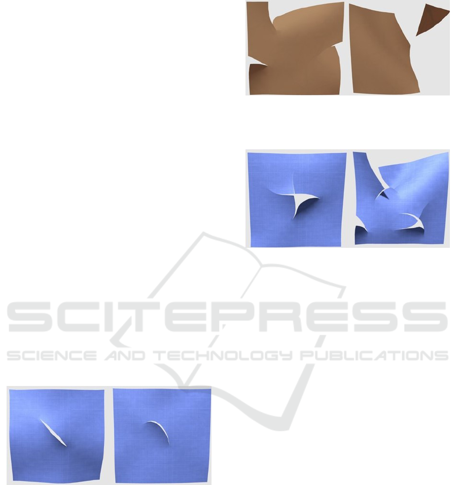
5.1 Complex Cut Surfaces
Our method can produce realistic and accurate cut
surfaces with arbitrary shapes even in low-resolution
meshes. Note that all meshes illustrated in figures are
constructed by 800 initial triangles. Figure 5 shows
two example cuts (straight and curved). Figure 6 illus-
trates partial cuts which include cut from an edge (the
left) and cut part of mesh entirely out (the right). Fig-
ure 7 shows a re-cut (the left) and multiple cuts (the
right). Within a single mesh. Intuitively, our method
can provide a high-detailed cut surface independent
of resolution requirements. Moreover, the visual out-
puts also demonstrate how our method can produce
realistic cut incision with accurate physical behaviors
which involve substantial bending, swirling and flip-
ping.
Figure 5: Different shapes of single cut within a mesh. The
left shows a straight cut, while the right shows a curved cut.
Both simulations use a mesh of 800 initial triangles.
5.2 Mesh Quality Comparison
We present a localized optimization to efficiently re-
mesh the ill-shape triangles and their one-ring neigh-
bors. Figure 8 compares the mesh after our cutting
simulation with the method that simply subdivides in-
tersected triangles with a static re-connect order (con-
ventional subdivision). Intuitively, the conventional
subdivision can easily generate ill-shaped triangles
Figure 6: Examples of cuts that (left) cut from a side and
(right) cut part of the mesh out. Note that each subdivided
mesh subsequently has an independent deformation basis
function.
Figure 7: High-detail cut surfaces which demonstrate in-
tersected cut (left) and multiple cuts within a single mesh
(right).
leading to unexpected cut edge distortion and abnor-
mal deformation. In contrast, our method can avoid
ill-shaped triangles, making the simulation numeri-
cally stable and visually convincing. Furthermore, we
locally increase the details only around the incision;
therefore the rest of the mesh maintains the level of
detail to ensure a focused computation cost.
Figure 9 illustrates how our adaptive subdivision
scheme generates optimal triangulation with low av-
erage aspect ratio (less than 3). We implemented the
conventional subdivision which simply subdividing
original triangle into three along the cut path on the
same size model. As shown in the figure, the con-
ventional subdivision can easily generate inefficient
shaped or sized triangles with a high aspect ratio.
In contrast, our method optimizes all such triangles
whose aspect ratio is more than 3 to re-generate a sta-
ble and physically accurate incision.
5.3 Computation Cost Measurement
Table 1 shows the average computation times per sim-
ulation step for various levels of mesh resolution. We
apply an implicit time-based solver for the viscoelas-
tic deformation. The first column represents the scale
of mesh, which followed by geometry modification
cost that relates to the initial Delaunay triangulation
generation and localized optimization. The third col-
umn is the physics updating time after the re-meshing
GRAPP 2018 - International Conference on Computer Graphics Theory and Applications
188
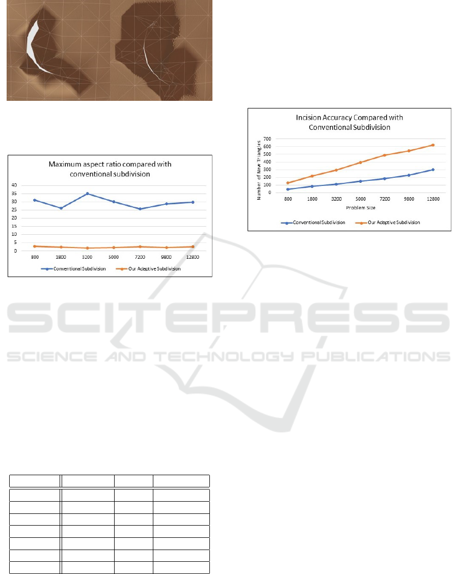
Figure 8: With simply subdividing intersected elements
without further optimization (left), it leads to a swirling
cut edge. In contrast, our method (right) provides smooth,
physically accurate incisions.
Figure 9: Comparison of maximum aspect ratio after cut-
ting operation with conventional subdivision that without
any further optimization.
operation is completed. The last column shows the
total computation time of each cutting experiment.
The results indicate that our algorithm provides a
fast cutting process. Even in the highest quality model
(12800 triangles), the total computation time in each
call of our cutting method is less than six millisec-
onds. Moreover, the differential value of the total time
taken between the 800 triangles mesh and the 12800
triangles mesh is only 3.915 milliseconds, which sug-
gests that our cutting method can be integrated into a
high-quality model simulation in real-time.
Table 1: Performance measure (ms).
Triangles Geometry Solver Total Time
800 0.865 0.203 1.068
1800 0.947 0.278 1.225
3200 1.246 0.356 1.602
5000 1.987 0.390 2.377
7200 2.935 0.683 3.618
9800 3.598 0.702 4.30
12800 4.130 0.853 4.983
5.4 Level of Details Comparison
Figure 10 compares the level of details around the cut
incision with conventional subdivision (which only
subdivide the intersected triangles into three smaller
triangles along the cut path). Our method optimizes
the triangles generated by subdivision, with a small
number of additional DOFs.
Figure 10: Comparison of the level of detail around the inci-
sion with conventional subdivision scheme without further
subdivision.
6 CONCLUSION AND FUTURE
WORK
The cutting method described in this paper introduces
three novel contributions to the area of 3D simula-
tions of mesh cutting using FEMs. The first signifi-
cant contribution is the method of adopting the most
efficient incremental Delaunay generation algorithm,
Bowyer-Watson algorithm, performing lower compu-
tational overhead than existing algorithms to generate
appropriate triangulation with low aspect ratio after
cutting occurs. Secondly, we achieved robust simula-
tion of complex cuts, such as re-cuts and intersected
cuts. Finally, we generate the optimal modified tri-
angulation by operating the local split optimization to
efficiently handle ill-shaped elements maintaining the
mesh quality with the maximum aspect ratio in the
triangulation of less than 3.
Our future work will focus on fusing the surface
model topology with the geometric model to produce
a component-based model to simulate detailed skin
model.
ACKNOWLEDGEMENTS
We thank all help and suggestion from Newcastle uni-
versity Game research group.
Accurate Real-time Complex Cutting in Finite Element Modeling
189

REFERENCES
Baraff, D. and Witkin, A. (1998). Large steps in cloth
simulation. In Proceedings of the 25th annual con-
ference on Computer graphics and interactive tech-
niques, pages 43–54. ACM.
Bender, J. and Deul, C. (2013). Adaptive cloth simula-
tion using corotational finite elements. Computers &
Graphics, 37(7):820–829.
Bielser, D., Glardon, P., Teschner, M., and Gross, M.
(2004). A state machine for real-time cutting of tetra-
hedral meshes. Graphical Models, 66(6):398–417.
Bowyer, A. (1981). Computing dirichlet tessellations. The
computer journal, 24(2):162–166.
Busaryev, O., Dey, T. K., and Wang, H. (2013). Adaptive
fracture simulation of multi-layered thin plates. ACM
Transactions on Graphics (TOG), 32(4):52.
Cakir, O., Yazici, R., and Cakir, O. (2009). Real-time
cutting simulation based on stiffness-warped fem.
In Computer and Information Sciences, 2009. ISCIS
2009. 24th International Symposium on, pages 721–
724. IEEE.
Cotin, S., Delingette, H., and Ayache, N. (2000). A hy-
brid elastic model for real-time cutting, deformations,
and force feedback for surgery training and simula-
tion. The Visual Computer, 16(8):437–452.
Courtecuisse, H., Jung, H., Allard, J., Duriez, C., Lee,
D. Y., and Cotin, S. (2010). Gpu-based real-time
soft tissue deformation with cutting and haptic feed-
back. Progress in biophysics and molecular biology,
103(2):159–168.
Felippa, C. A. and Haugen, B. (2005). A unified formu-
lation of small-strain corotational finite elements: I.
theory. Computer Methods in Applied Mechanics and
Engineering, 194(21):2285–2335.
Georgii, J. and Westermann, R. (2008). Corotated finite
elements made fast and stable. VRIPHYS, 8:11–19.
Kaufmann, P., Martin, S., Botsch, M., Grinspun, E., and
Gross, M. (2009). Enrichment textures for detailed
cutting of shells. In ACM Transactions on Graphics
(TOG), volume 28, page 50. ACM.
Koh, W., Narain, R., and O’Brien, J. F. (2014). View-
dependent adaptive cloth simulation. In Proceedings
of the ACM SIGGRAPH/Eurographics Symposium on
Computer Animation, pages 159–166. Eurographics
Association.
Koschier, D., Bender, J., and Thuerey, N. (2017). Robust
extended finite elements for complex cutting of de-
formables. ACM Transactions on Graphics (TOG),
36(4):55.
Narain, R., Pfaff, T., and O’Brien, J. F. (2013). Folding
and crumpling adaptive sheets. ACM Transactions on
Graphics (TOG), 32(4):51.
Nesme, M., Kry, P. G., Je
ˇ
r
´
abkov
´
a, L., and Faure, F. (2009).
Preserving topology and elasticity for embedded de-
formable models. In ACM Transactions on Graphics
(TOG), volume 28, page 52. ACM.
Nienhuys, H.-W. and van der Stappen, A. F. (2004). A de-
launay approach to interactive cutting in triangulated
surfaces. In Algorithmic Foundations of Robotics V,
pages 113–129. Springer.
Pfaff, T., Narain, R., de Joya, J. M., and O’Brien, J. F.
(2014). Adaptive tearing and cracking of thin sheets.
ACM Transactions on Graphics (TOG), 33(4):110.
Pietroni, N., Ganovelli, F., Cignoni, P., and Scopigno, R.
(2009). Splitting cubes: a fast and robust technique
for virtual cutting. The Visual Computer, 25(3):227–
239.
Rebay, S. (1993). Efficient unstructured mesh genera-
tion by means of delaunay triangulation and bowyer-
watson algorithm. Journal of computational physics,
106(1):125–138.
Seiler, M., Steinemann, D., Spillmann, J., and Harders, M.
(2011). Robust interactive cutting based on an adap-
tive octree simulation mesh. The Visual Computer,
27(6-8):519–529.
Serby, D., Harders, M., and Sz
´
ekely, G. (2001). A
new approach to cutting into finite element mod-
els. In Medical Image Computing and Computer-
Assisted Intervention–MICCAI 2001, pages 425–433.
Springer.
Shewchuk, J. R. (2002). Delaunay refinement algorithms
for triangular mesh generation. Computational geom-
etry, 22(1-3):21–74.
Sifakis, E., Der, K. G., and Fedkiw, R. (2007). Arbitrary
cutting of deformable tetrahedralized objects. In Pro-
ceedings of the 2007 ACM SIGGRAPH/Eurographics
symposium on Computer animation, pages 73–80. Eu-
rographics Association.
Souza, M. S., Wangenheim, A., and Comunello, E. (2014).
Fast simulation of cloth tearing. SBC Journal on In-
teractive Systems, 5(1):44–48.
Steinemann, D., Harders, M., Gross, M., and Szekely, G.
(2006). Hybrid cutting of deformable solids. In Vir-
tual Reality Conference, 2006, pages 35–42. IEEE.
Turkiyyah, G. M., Karam, W. B., Ajami, Z., and Nasri, A.
(2011). Mesh cutting during real-time physical simu-
lation. Computer-Aided Design, 43(7):809–819.
Wu, J., Westermann, R., and Dick, C. (2015). A survey
of physically based simulation of cuts in deformable
bodies. In Computer Graphics Forum, volume 34,
pages 161–187. Wiley Online Library.
Yeung, Y.-H., Crouch, J., and Pothen, A. (2016). Inter-
actively cutting and constraining vertices in meshes
using augmented matrices. ACM Transactions on
Graphics (TOG), 35(2):18.
GRAPP 2018 - International Conference on Computer Graphics Theory and Applications
190
