
Towards an Augmented Reality Head Mounted Display System
Providing Stereoscopic Wide Field of View for Indoor and Outdoor
Environments with Interaction through the Gaze Direction
Jessica Combier
1, 2
, Bertrand Vandeportaele
2
and Patrick Dan
`
es
2
1
ESSILOR International, Lab
`
ege, France
2
LAAS-CNRS, Universit
´
e de Toulouse, CNRS, UPS, Toulouse, France
Keywords:
Augmented Reality Head Mounted Device, Image Base Rendering, Fish-eye Stereo-vision System, SLAM,
Gaze Interaction.
Abstract:
An Augmented Reality prototype is presented. Its hardware architecture is composed of a Head Mounted
Display, a wide Field of View (FOV) stereo-vision passive system, a gaze tracker and a laptop. An associated
software architecture is proposed to immerse the user in augmented environments where he/she can move
freely. The system maps the unknown real-world (indoor or outdoor) environment and is localized into this
map by means of binocular state-of-the-art Simultaneous Localization and Mapping techniques. It overcomes
the FOV limitations of conventional augmented reality devices by using wide-angle cameras and associated
algorithms. It also solves the parallax issue induced by the distinct locations of the two cameras and of the
user’s eyes by using Depth Image Based Rendering. An embedded gaze tracker, together with environment
modeling techniques, enable gaze controlled interaction. A simple application is presented, in which a virtual
object is inserted into the user’s FOV and follows his/her gaze. While the targeted real time performance has
not yet been achieved, the paper discusses ways to improve both frame rate and latency. Other future works
are also overviewed.
1 INTRODUCTION
Nowadays, Virtual Reality (VR) is commonly used
to generate realistic images of virtual environments.
These images can be displayed on VR headsets in or-
der to create an immersive experience. Besides, Aug-
mented Reality (AR) consists in enhancing the user’s
current perception of reality by attaching some virtual
elements to the real-world environment. AR thus re-
quires a fine mixing of real and synthetic elements.
AR and VR can be used in several applications,
such as teleconferencing, gaming, entertainment, edu-
cation, medical assistance, or to help a worker to carry
out his/her tasks. A review of AR applications is avai-
lable in (Carmigniani et al., 2011).
AR devices mounted on headsets can be categori-
zed as Optical See-Through Head Mounted Displays
(OSTHMDs) and Video See-Through Head Mounted
Displays (VSTHMDs). Their respective advantages
and drawbacks can be summarized as follows:
• An OSTHMD is close to traditional spectacles,
as the user sees the real environment through the
transparent lenses used as a screen. A projector is
usually located within the arms, and the virtual
content is displayed through a semi-transparent
mirror in front of each user’s eye.
• A VSTHMD consists in the assembly of an opa-
que screen with lenses placed in front of the user’s
eyes. It is equipped with cameras in charge of
grabbing images of the environment. These ima-
ges are augmented with virtual content, then dis-
played.
Current AR systems have some limitations, which
prevent a comfortable experience. For instance:
• The field of view (FOV) of traditional perspective
cameras is usually about 120 degrees. This is too
small to map the wide human FOV (about 180 de-
grees in azimuth).
• The cameras and the user’s eyes are not located at
the same positions, resulting in different percepti-
ons of the scene. When the cameras are aligned
with the eyes and have the same inter-ocular dis-
tance (Steptoe et al., 2014), (Pankratz and Klinker,
2015), this difference can be neglected. In other
Combier, J., Vandeportaele, B. and Danès, P.
Towards an Augmented Reality Head Mounted Display System Providing Stereoscopic Wide Field of View for Indoor and Outdoor Environments with Interaction through the Gaze Direction.
DOI: 10.5220/0006536500170027
In Proceedings of the 13th International Joint Conference on Computer Vision, Imaging and Computer Graphics Theory and Applications (VISIGRAPP 2018) - Volume 4: VISAPP, pages
17-27
ISBN: 978-989-758-290-5
Copyright © 2018 by SCITEPRESS – Science and Technology Publications, Lda. All rights reserved
17

cases, it has to be taken into account so as to avoid
discomfort, nausea or headaches for the user.
• The real environment has to be analyzed in order
to incorporate virtual content: recognizing objects
or persons, detecting scene structures as ground
or walls, etc. Three-dimensional mapping can ea-
sily be achieved with active vision devices (such
as Kinect) that project light onto the environment.
These systems work well in indoor scenes but are
subject to failure outside, due to the lighting of the
sun which hinders the detection of the projected
light.
• The user’s head position and orientation has to be
determined with respect to the scene in order to
display a virtual content at the correct pose. To
achieve this, additional sensors can be used (Iner-
tial Measurement Unit (IMU) and/or motion cap-
ture systems), resulting in added complexity and
cost for the system. Another possible approach is
to use the images provided by the embedded ca-
meras to estimate the user’s pose, by observing
specific recognizable objects (2D tags, markers or
known patterns) added in the scene at known po-
sitions. Nevertheless, it is desirable to avoid the
use of such dedicated targets by using detection
and mapping of existing objects so as to extend
the possibilities of use in unknown environments.
• The system has to satisfy strong real time con-
straints in order to account for the head motion.
In case of AR through OSTHMD, lags are cle-
arly perceived due to the wrong location of the
virtual elements displayed over the real scene.
For the VSTHMD, the whole image (real envi-
ronment and virtual content) is delayed, resulting
in discomfort because of the mismatch between
the user’s visual and inner ear systems. This dis-
comfort is called ”motion sickness” or ”cyber-
sickness”. For example, the VR headset Oculus
Rift has shown this side effect (Munafo et al.,
2017).
Our purpose is to develop a system that addres-
ses all these problems and is suited to both indoor
and outdoor environments. Our research targets the
same goal as (Keller et al., 2005), whose orthoscopic
VSTHMD device addresses the parallax induced by
the gap between the mounted cameras and the user’s
eyes. However, we propose to overcome this pro-
blem through computer image synthesis. Such met-
hods have been used by (Saito, 2011) and (De Sor-
bier et al., 2010), by means of active time-of-flight
sensors, while our approach relies on passive stereo-
vision. A passive system is suggested by (Lai et al.,
2016a), which emulates an HMD with different num-
ber of cameras in a synthetic scene. Our prototype
can be compared with the commercially available ste-
reoscopic Wrap 1200DXAR of Vuzix (Vuzix, 2017).
However, it provides a wider field of view, a higher re-
solution, and works in unknown environments thanks
to its integrated SLAM. It should not be compared
with a VR HMD like the HTC Vive (Vive, 2017),
which provides a single facing forward camera. It is
closer to the future Acer Windows mixed reality head-
set, which is endowed with two cameras on the front
side (Acer, 2017). However, the way how this com-
mercial device handles the parallax problem (which
needs to be solved as the stereo rig baseline is wider
than the interocular space) is not made explicit in the
product documentation. In addition, according to the
product technical data, the headset seems to have a
SLAM and a 3D reconstruction algorithm, but it does
not include a gaze tracker. Our system also integra-
tes some interaction abilities through the user’s gaze,
a problem that is addressed by devices from Tobiipro
(TobiiPro, 2017).
This paper describes the current state of our pro-
ject, as well as the main hardware and software com-
ponents developed. It is organized as follows. In
Section 2, a general description of the proposed sy-
stem is presented. We argue the use of wide an-
gle cameras and present our stereoscopic model in
Section 3. The main modules of the system, i.e.,
binocular Simultaneous Localization And Mapping
(SLAM), Image Generation (IG) and Gaze Tracking
(GT), are respectively described in Sections 4, 5 and
6. Finally, Section 7 presents the currently reached
real time performance, and future work is introduced
in Section 8.
2 OVERVIEW OF THE PROJECT
AND PROTOTYPE
2.1 Proposed Hardware Architecture
The desired properties of the targeted system are de-
picted below.
• The system must be usable in unknown ind-
oor/outdoor environments without requiring the
deployment of additional external parts (for in-
stance, fixed cameras or 2D tags).
• The system must be carried by the user, for in-
stance in a backpack.
• The system must be able to display AR content in
order to fill the user’s FOV.
• The system must be comfortable and provide im-
mersive visual effects.
VISAPP 2018 - International Conference on Computer Vision Theory and Applications
18
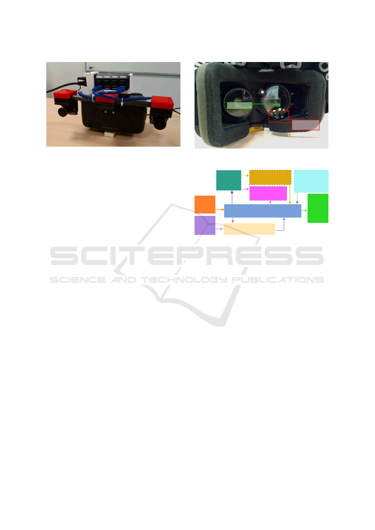
Figure 1: Front view of the AR prototype.
• The system must enable interaction with the vir-
tual environment through the tracking of the
user’s line of sight.
An OSTHMD would fit these requirements better.
But due to the lack of wide FOV devices on the mar-
ket, we decided to use an available VSTHMD with
a 110 degrees FOV (Oculus DK2 by (Oculus, 2017))
in order to develop the proposed hardware and soft-
ware modules. Importantly, the proposed solutions
can be transposed to any future OSTHMD. For the
same reason, as the human monocular FOV covers
about 180 degrees horizontally and 130 degrees ver-
tically, we decided to use wide FOV cameras to per-
ceive the scene even though the used VSTHMD has
a smaller FOV. A stereo-vision system composed of
two synchronized 1.3 Megapixels global shutter ca-
meras with fish-eye lenses has then been designed,
providing stereoscopic 180 degrees FOV. These two
cameras have been positioned on the prototype so as
to be localizable on an OSTHMD, i.e., at the extremi-
ties of the spectacle arms instead of beyond the user’s
eyes as this last option would obstruct the FOV. So,
a synthetic rendering of the scene captured by these
cameras must be generated and suitably displayed to
the user. The synthesis of these images is performed
through a process named Depth Image Based Rende-
ring (DIBR), presented in the sequel.
Figure 1 shows a front view of the designed pro-
totype. The VSTHMD lies in the center of the image,
while two fish-eye cameras are on the sides.
To measure the user’s line of sight, a custom micro
camera coupled with an infrared lighting system have
been designed and inserted into the HMD (Figure 2).
This device measures the user’s right eye position as
well as its gaze direction, so that he/she can interact
with the system just by gazing.
2D tags or other camera(s) fixed in the environ-
ment can be used to localize the HMD with good per-
formance (accuracy and latency). However, for the
system to work in unknown environments, we inte-
infra-red
LEDs
IR camera
Figure 2: Back view of the AR prototype, showing the cus-
tom gaze tracker.
Gaze
tracker
camera
Stereo
vision
cameras
SLAM
MODULE
3D model
of the environment
3D
SYNTHETIC
MODEL
GENERATION
MODULE
HMD pose
IMAGE GENERATION
MODULE
3D GAZE TRACKER
MODULE
Stereo
Display
Head
Mounted
Figure 3: Block diagram of the general architecture.
grated a binocular SLAM that processes the data pro-
vided by the embedded stereoscopic sensor.
2.2 Software Architecture
Figure 3 summarizes the main components of the sy-
stem together with their data flow. The Image Genera-
tion (IG) module generates the required color images
and depth maps. In addition, it generates images to be
used for SLAM on the basis of the simple pinhole ca-
mera projection model. It also converts images grab-
bed by the stereo-vision system into synthetic images
suited to the viewpoint of the user’s eyes. To compute
synthetic data to be displayed on the HMD, this mo-
dule needs the two captured stereoscopic images, the
HMD pose, the model of the environment estimated
by SLAM, the 3D model of the virtual object which
must be superimposed on the real scene, and the 3D
point of interest pointed by the user’s gaze. This last
3D point is deduced from the 3D gaze computed by
the Gaze Tracker (GT) module and from the depth
map computed by the IG module, by means of stan-
dard stereo-correlation techniques.
The IG module is composed of two stages. First,
a Depth Image Based Rendering (DIBR) algorithm
converts the stereoscopic input images into images
corresponding to a different viewpoint. This algo-
rithm includes a stereo matching stage which com-
Towards an Augmented Reality Head Mounted Display System Providing Stereoscopic Wide Field of View for Indoor and Outdoor
Environments with Interaction through the Gaze Direction
19

putes depth maps for both input camera images. A
second stage of the IG module augments the synthesi-
zed image with the 3D synthetic model. More details
are given in Section 5.
Some algorithms are available off-the-shelf under
open-source licences:
• The selected SLAM implementation is ORB-
SLAM2, an open-source C++ software developed
by Mur-Artal et al. (Mur-Artal et al., 2015) using
Oriented FAST and Rotated BRIEF (ORB) featu-
res. A great advantage of this implementation is
the robustness provided by its ability to re-localize
the camera.
• The stereo matching software is an open source
C++ code from external contribution distributed
with OpenCV 3.1.
Other algorithms have been specifically developed for
our project:
• An existing monocular open-source toolbox for
omni-directional camera calibration has been ex-
tended to a binocular setup (see Section 3). This
allows to calibrate the wide FOV camera stereo-
vision system in order to perform 3D measure-
ments from the images.
• The Depth Image Based Rendering has been co-
ded to generate synthetic images from various vie-
wpoints.
• The Gaze Tracker provides the gaze direction and
corresponding 3D points in the scene.
In order to easily develop and parallelize modular
software, we have used the ROS (Robot Operating
System) middleware.
2.3 Combined Use of DIBR and Stereo
Matching
Active vision systems based on time-of-flight or
structured light projection are preferred in many ap-
plications over passive stereo-vision systems because
they provide depth images in poorly textured environ-
ments at a high frame rate. However, these sensors
tend not to be efficient in outdoor environments. Mo-
reover, we are not aware of any available active device
that provides the requested FOV for our application.
For these reasons, we chose passive stereo-vision.
We argue that the combination of DIBR and pas-
sive stereo-vision is a right choice. Stereo-vision
would generate imprecise depth maps in untextured
areas because the values of close pixels in the images
would be similar to each other. For a near viewpoint,
DIBR can use these erroneous (but close) values to
generate the pixels of the synthetic images. The same
holds for repetitive textures which are likely to break
down stereo-vision, as the DIBR can use patches of
images that where not taken at the right locations but
have the same appearance. So even when stereo-
vision fails, the DIBR can generate visually accep-
table images for the user.
3 STEREOSCOPIC LARGE
FIELD OF VIEW FOR VSTHMD
We use a pair of fish-eye cameras to obtain stereosco-
pic images of the scene and to allow interaction over
the full human FOV. Even if the Oculus FOV is li-
mited to about 110 degrees, we anticipated for future
HMDs which will provide wider FOV.
As a side benefit, the wide FOV cameras pro-
vide more distinguishable features for SLAM. Indeed,
when dealing with locally repetitive textures or textu-
reless areas in the environment, a SLAM using tradi-
tional small FOV cameras is likely to fail. Contrarily,
wide angle cameras allow to keep track of the camera
pose by exploiting features located on the borders of
the FOV.
During our development, a stereo calibration soft-
ware for fish-eye cameras was supposed to be avai-
lable in the OpenCV open-source computer vision
library but its geometric model is just an extension
of the standard pinhole camera model with additio-
nal degrees of freedom to account for radial distor-
tions. This model has proven not to be efficient for
real wide angle cameras (FOV over 120 degrees). We
decided to use a better fitted model proposed by (Sca-
ramuzza et al., 2006) who open sourced OcamCalib,
a Matlab toolbox for omni-directional (dioptric and
catadioptric) camera calibration using this model. We
have extended this toolbox to allow the calibration of
stereo-vision systems.
The used model assumes that the cameras are cen-
tral systems, i.e., all the perceived rays intersect at a
single point. The model is rotationally symmetrical
with respect to the z axis. It maps a 2D point (u, v)
in a virtual normalized image plane to a 3D vector P
(direction of ray) through a polynomial function f as
shown in Equations (1) and (2). The degree of the po-
lynomial can be freely chosen, and a quartic equation
model proved to be a good compromise as stated by
Scaramuzza and measured in our own experiments.
P =
x
y
z
=
u
v
f (ρ) = f (
√
u
2
+ v
2
)
(1)
f (ρ) = a
1
+ a
2
ρ + a
3
ρ
2
+ a
4
ρ
3
+ a
5
ρ
4
+ . . . (2)
VISAPP 2018 - International Conference on Computer Vision Theory and Applications
20

Small misalignment between sensor, lens or mir-
rors are modeled using an affine 2D transformation
as shown in equation (3), where (u
0
, v
0
) stands for the
real distorted coordinates in the sensor image plane
and (u, v) are ideal undistorted ones in a virtual nor-
malized image plane.
u
0
v
0
=
c d
e 1
u
v
+
xc
0
yc
0
(3)
The monocular model for the camera i is hence
parameterized by the set of intrinsic parameters: P
i
=
(c, d, e, xc
0
, yc
0
, a
1
, a
2
, a
3
, a
4
, a
5
).
We propose to extend this model to a stereoscopic
version consisting of two independent monocular mo-
dels parameterized by P
i
and P
j
and related by a 6 dof
rigid transformation modeling the translation (t vec-
tor) and rotation (r vector using Rodrigues parametri-
zation) between the two camera frames. It allows the
automatic estimation of the stereo model parameters
using pairs of (synchronized) images of a standard
checkerboard pattern. It first performs two individual
monocular calibrations using the corresponding ima-
ges. It then estimates r and t using the previously
computed intrinsic parameters P
i
and P
j
. It finally re-
fines the complete set of parameters using nonlinear
optimization. Once these parameters are estimated,
two 2D maps are pre-computed to generate pairs of
epipolar rectified images. 3D points are observed to
the same horizontal 2D lines in these two rectified
images. This permits dense depth maps to be obtai-
ned using fast stereo-matching techniques. Figure 4
shows the different images involved in the 3D dense
modeling process from the left camera point of view.
4 BINOCULAR SLAM
The Oculus DK2 comes with its own localization sy-
stem. This system is composed of an IMU and a ca-
mera that has to be fixed in the environment. This ca-
mera perceives the pattern of infra-red LEDs covering
the HMD and deduces the HMD relative pose, assu-
ming the HMD stays inside its FOV. This prevents the
user from moving freely in the environment. To cir-
cumvent this, we use Simultaneous Localization And
Mapping (SLAM) to localize the HMD in unknown
and virtually unbounded environments.
Vision based SLAM continuously enriches a 3D
map of the scene and localizes a camera in this map
from the images it delivers. While monocular SLAM
provides the camera’s poses up to an unknown scale
and requires the scene to be observed from different
locations to infer the 3D map, binocular SLAM is able
to estimate the scale and can integrate 3D points in the
map as soon as they appear in the stereoscopic FOV of
the system. Thus, we integrated the binocular ORB-
SLAM2 in our system. For the moment, the camera’s
wide FOV is not fully exploited as ORB-SLAM2 only
integrates the pinhole camera model. Hence, the ge-
nerated epipolar rectified images (Figure 4 (b)) are
used, covering about a 120 degrees FOV.
5 IMAGE GENERATION
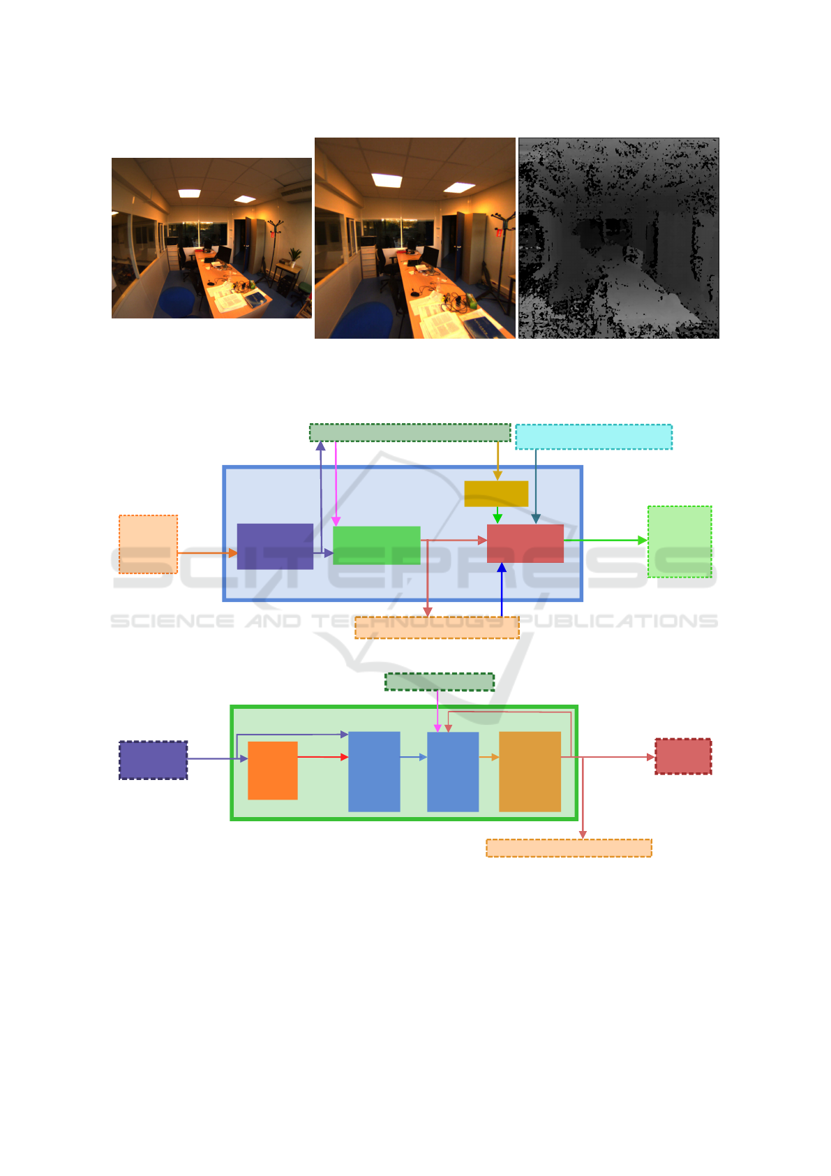
5.1 Pipeline
The Image Generation (IG) module is composed of a
sequence of sub-modules as shown in Figure 5. In a
first stage, the epipolar rectification is performed so
as to provide images to the SLAM and DIBR modu-
les. The latter is in charge of rendering the images
(and disparity maps) at the user’s eyes position. The
IG modules also performs simple scene analysis from
the generated SLAM point cloud and augments the
images with the 3D virtual content.
5.2 DIBR
The internal structure of the Depth Image Based Ren-
dering (DIBR) module is shown in Figure 6.
• The first stage performs the stereo matching on
the epipolar rectified images. We use the open-
source C++ implementation of Semi Global Block
Matching from OpenCV 3.1. The resulting dispa-
rity maps being noisy, a filtering is introduced, as
proposed by (Kauff et al., 2007).
• The second stage is in charge of 3D warping, i.e.,
the projection of images and depth maps on synt-
hetic cameras at distinct poses. To this aim, a
3D point cloud is generated from the depth maps
pixels. These points are then rotated, translated
and projected to the synthetic cameras so as to
render corresponding synthetic images and depth
maps. Small holes are generated in the rendered
images for multiple reasons: there is no one-to-
one pixel correspondence between the input and
generated images; the change of viewpoint requi-
res to render parts of the scene that were not ob-
served in the input image. We partially solve this
problem by using the image content from the two
cameras in order to render each synthetic images,
i.e., the two 3D point clouds are virtually pro-
jected to each of the two synthetic cameras using
stereo 3D warping. The remaining holes are re-
moved in the two next stages of the pipeline.
Towards an Augmented Reality Head Mounted Display System Providing Stereoscopic Wide Field of View for Indoor and Outdoor
Environments with Interaction through the Gaze Direction
21
(a)
(b) (c)
Figure 4: (a) an image captured from one camera, (b) the corresponding epipolar rectified image and (c) the computed disparity
map (the closer areas appear brighter, and completely black regions correspond to undetermined disparity, for instance because
of lack of texture).
3D model of the
environment
3D synthetic model pose
3D SYNTHETIC MODEL
GENERATION MODULE
synthetic right eye
depth map only
3D gaze POI
augmented
images
Scene
Analysis
DIBR
MODULE
AR Content
Projection
IMAGE GENERATION
MODULE
3D GAZE TRACKER MODULE
HMD pose
synthetic
images
and depth
maps
rectified
images
Stereo
vision
cameras
SLAM MODULE
Head
Mounted
Stereo
Display
Epipolar
rectification
input
images
3D Synthetic Model
Figure 5: Image Generation block diagram.
rectified
images
previous synthesized data
synthesized
images and
depthmaps
from the
user’s eyes
viewpoint
without holes
depth
maps
from the
cameras
viewpoint
DIBR MODULE
Stereo
matching
and
filtering
Stereo 3D
warping
from
current
views
Stereo 3D
warping
from
previous
views
Hole
filling
using
interpolation
SLAM MODULE
3D GAZE TRACKER MODULE
AR content
projection
HMD pose
Epipolar
Rectification
Figure 6: DIBR block diagram.
• The third stage carries out another 3D warping to
enrich the view, considering the 3D point cloud
built at the previous iteration and the motion be-
tween the two point clouds obtained from the
SLAM module. This allows to use some image
content that may not be visible anymore in the in-
put stereoscopic images and to increase the tem-
poral consistency of the generated images.
• The final stage fills the remaining holes by inter-
polation for depth maps and images. Bilinear in-
terpolation is used to fill holes of the depth maps,
even if this tends to soften the object contours.
An example of DIBR rendered image using our pi-
peline is shown in Figure 7.
VISAPP 2018 - International Conference on Computer Vision Theory and Applications
22

5.3 Scene Analysis
The surrounding environment is incrementally mo-
deled by a 3D point cloud using SLAM while the
user is moving. This 3D model is analyzed in order
to detect geometric structures and to determine suit-
able areas where to add the virtual content. For the
moment, we have implemented a simple robust plane
estimation from the 3D point cloud in order to posi-
tion moving 3D models onto it, as shown in Figure 8.
More complex processing could be considered, e.g.,
the detection and skeleton fitting of an human to aug-
ment him/her with virtual clothes.
5.4 AR Content Projection
Conventional OpenGL projection of textured 3D mes-
hed models is performed to get augmented stereosco-
pic images. The rendering is done using the Oculus
DK2 Software Development Kit which generates suit-
able camera projections for the two eyes. The SDK
also provides a shader program to process the rende-
red images in order to take into account the chroma-
tic aberrations caused by the low-cost optical system
of the device. The synthetic images generated by the
DIBR module are used as background while the synt-
hetic depth maps serve to initialize the Z-buffer. As
the OpenGL rendering cameras rely on the same ge-
ometric models as those of the DIBR, the 3D objects
are easily rendered and integrated inside the real en-
vironment. The Z-buffer test determines for each ren-
dered pixel whether it is occluded or not by the real
scene.
Figure 8 shows an augmented stereoscopic image
generated by our system, as displayed in the HMD.
The rendering stage is able to take into account the
user’s gaze direction computed by the 3D GT module
in order to interact with the augmented elements, as
shown in the following section.
6 GAZE TRACKER AND
INTERACTION
Our custom gaze tracker fits inside the HMD re-
stricted space. Its hardware elements are a micro ca-
mera endowed with an infra-red (IR) bandpass filter
and two IR LEDs. A two-eye gaze tracker could pro-
vide the 3D location in the scene of the Point Of In-
terest (POI) observed by the user, by intersecting the
left and right gaze directions. However, we have cho-
sen a single-eye gaze tracker to minimize the number
of hardware elements to integrate, and because we use
the information provided by the stereo-vision system
to assess the POI as explained later. Our solution is
visible in Figure 2. The eye is illuminated by the IR
LEDs and observed by the camera. Thanks to the IR
filter, the camera is not disturbed by the light emitted
by the display. The resulting hardware requires just a
few millimeters and does not obstruct the FOV of the
user, hence this architecture could also be used inside
an OSTHMD.
The GT software module is composed of two main
parts that process the images from the gaze tracker
camera: the first fits an ellipse on the pupil contour
and the second deduces the gaze direction from the
pupil center (u
pc
, v
pc
). For the gaze direction estima-
tion, we use a polynomial model to compute the pixel
(u
s
, v
s
) on the scene camera where the eye is directed
to (see equations 4 and 5). Our method for the pu-
pil detection and gaze estimation is similar to that of
(Kassner et al., 2014).
u
s
v
s
=
f
1
(u
pc
, v
pc
)
f
2
(u
pc
, v
pc
)
(4)
f
i
(u
pc
, v
pc
) = a
i1
+ a
i2
u
pc
+ a
i3
v
pc
+a
i4
u
2
pc
+ a
i5
v
2
pc
+ a
i6
u
pc
v
pc
(5)
A calibration must be conducted in order to es-
timate the parameters (a
11
, ..., a
16
) and (a
21
, ..., a
26
).
In this preliminary stage, the user must successively
look towards nine points homogeneously distributed
on the screen. This calibration has to be done each
time the user wears again the HMD.
Once this calibration is achieved, our system is
able to compute in real time the gazed 3D POI. As
shown in Figure 5, the DIBR module provides the GT
module with a synthetic disparity map corresponding
to the user’s right eye location. The POI is computed
by intersecting the 3D gaze direction and this dispa-
rity map. Using this POI, the user is able to interact
with the system. For instance, we have implemented
a simple application where the user’s gaze defines the
position of an inlayed 3D model of a penguin. This
penguin, rendered in Figure 8, moves according to
the user’s gaze along the top surface of a desk, whose
geometry is estimated from the depth maps and the
sparse 3D model computed by SLAM.
7 RESULTS AND REAL TIME
CONCERNS
7.1 Real Time Concerns
Strong real time constraints are imposed on the sy-
stem so as to avoid the user’s discomfort when his/her
Towards an Augmented Reality Head Mounted Display System Providing Stereoscopic Wide Field of View for Indoor and Outdoor
Environments with Interaction through the Gaze Direction
23
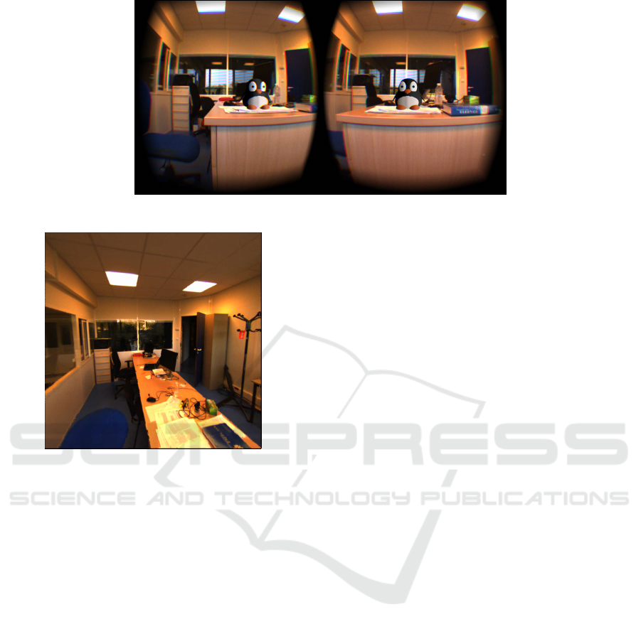
Figure 8: Augmented stereoscopic images displayed in the HMD.
Figure 7: Image synthesized from Figure 4 (b) by DIBR.
visual and inner ear systems provide inconsistent pose
estimations due to lag in the displayed images. Frame
rate and latency are common constraints for gaming
applications using HMD. The (Oculus, 2017) com-
pany suggests at least 70 FPS for the Oculus DK2.
The required frame rate depends on the application.
For virtual environments in HMD, (Chen and Thropp,
2007) advises a minimum threshold of 17.5 Hz. For
applications involving fast motions, a high frame rate
is mandatory. Claypool et al. (Claypool et al., 2006)
describe the frame rate impact on user perception and
gamer performance. The latency between the HMD’s
motion and the display of the images must also be
limited so as not to be perceptible. Ref. (Adelstein
et al., 2003) claims that it should not be higher than
17 ms.
Early encouraging results of the complete pro-
totype have been demonstrated through the simple
augmentation example presented above. Though the
generated images are acceptable in static scenarios,
the achieved FPS is far too low for now to enable a
real interaction. The achieved FPS for the demon-
strated penguin complete application is slightly be-
low 1 FPS for the current version of the system. The
corresponding latency is over 1 second, clearly above
acceptable values. The used laptop computer embeds
an Intel Core i7-4800MQ octocore CPU running at
2.70GHz and a Quadro K1100M/PCIe/SSE2 graphic
chipset.
The profiling of individual modules has led to the
following conclusions:
• The duration of epipolar rectification can be neg-
lected, as this process only involves bilinear inter-
polation for pixels locations stored in precompu-
ted tables.
• Binocular SLAM is used on half resolution ima-
ges (540x540 pixels) with a maximum limit of
1000 detected and tracked features. The max-
imum attainable frequency for SLAM alone is
about 13 FPS when 3 CPU cores are involved. As
the display is done at 60 FPS, a pose computed by
SLAM must thus be used several times by the IG
module.
• The IG stage is relatively time consuming. The
entailed OpenCV Semi Global Block Matching
CPU implementation itself requires nearly one se-
cond for one CPU core to correlate the images.
The stereo 3D warping, hole filling and imple-
mented scene analysis (consisting in simple ro-
bust plane fitting) stages require negligible time in
comparison. The projection of AR content being
done by the GPU and the projected model being
composed of just a few hundred of textured tri-
angles, its is achieved at high FPS. However, the
required time to transfer the background images
and depth maps appears to be a bottleneck.
• The GT module involves quite simple computa-
tions. So, it can be run at more than 50 FPS on
a single CPU core. However, it is limited by the
embedded camera rate of 30 FPS.
7.2 Results
In addition to the penguin interaction, we conduct
a simple application to evaluate the impact of the
VISAPP 2018 - International Conference on Computer Vision Theory and Applications
24
VSTHMD on the 3D environment perception. The
idea is to check if the user sees the 3D synthetic ob-
jects at the location where they should be. If the user
does not wear an HMD, he/she is able to point out a
target point in the scene after closing his/her eyes. We
first conduct an experiment without HMD: the user
seated at a desk looks at a tag on the desk, closes
his/her eyes and puts another tag on the remembered
first tag location. This step is repeated for different
tag locations. Both tags are localized by a camera
with the AprilTags library (Olson, 2011) to compute
the distance between them. This distance indicates
the perception error. As a result, the target point can
be found with a RMSE (Root Mean Square Error) of
1.84 cm. Then, to evaluate the 3D perception, this
principle is tested when the user sees the environment
through the HMD.
The procedure is the following. A checkerboard
is displayed through the Oculus on a plane detected
in the scene (a desk in our experiment). Successi-
vely different checkerboard squares light up to inte-
ract with the user seated at the desk. He/She has to
look carefully at the scene seen through the Oculus
and must remember where the lit up square is. Then
he/she closes his/her eyes and puts a tag at the remem-
bered square location. The stereo bench on the Oculus
detects tags. This experiment is done twice: without
DIBR, therefore the images from the stereo bench are
directly displayed in the HMD; and with DIBR, the-
refore the displayed images are synthesized at the eye
position.
It is important for the user to close his/her eyes
while he/she moves his/her hand to put the tag on the
square. If the user sees his/her hand, he/she will au-
tomatiquely correct his/her movement even if the per-
ception through the VSTHMD is wrong.
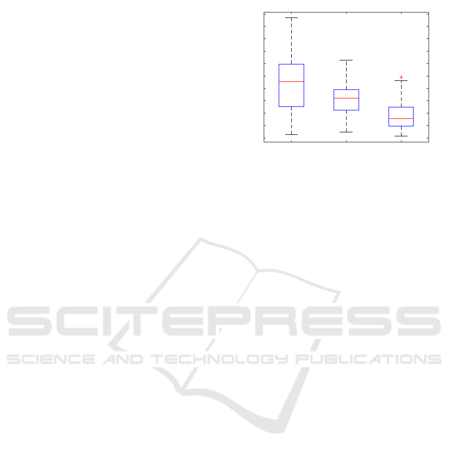
As a result, when the user wears the HMD, he/she
is able to find the square location with a RMSE of
4.42 cm without DIBR and 3.13 cm with DIBR. Both
experiments have been repeated 55 times for different
squares locations. The figure 9 details the results.
A rather similar experiment has been developed
independently, and published in a recent paper (Lai
et al., 2016b). In this paper, the user has to position a
cube on three distinct locations. To manage this task,
he/she has to remember the target position and close
his/her eyes during his/her hand movement, as we did.
8 FUTURE WORK
Our future works will primarily focus on reaching
real-time performance, but other aspects will also be
investigated:
without DIBR with DIBR without HMD
0
0.01
0.02
0.03
0.04
0.05
0.06
0.07
0.08
0.09
0.1
Figure 9: Perception error in meter for 3 experiments: from
left to right, results without DIBR, results with DIBR and
results without HMD.
• The algorithms have not been fully parallelized in
order to efficiently use the multi-core architecture
of the computer. Real time stereo matching al-
gorithms such as the one proposed by (Atzpadin
et al., 2004) could be used to drastically reduce
the computation time. Some of the algorithms
could also be ported to the GPU side to better use
this computing resource, in the vein of the DIBR
(Lai et al., 2016b). Even dedicated hardware (like
FPGA) could be envisaged to run the most deman-
ding tasks. The whole IG module, which mainly
runs on the CPU, would benefit from a GPU im-
plementation, as it only involves computations on
geometry and images. As speedup factors greater
than 30x are often observed for such problems,
therefore our goal appears within reach.
• In order to reduce the latency of the system, a
predictive algorithm could be introduced. For in-
stance, the integration of a motion model for the
HMD allows to predict its next pose and hence
the two user’s eyes location as shown in Figure 3.
While the current implementation assumes a static
model, an enriched HMD motion model could be
supplied with high frequency measurements from
an attached IMU so as to assess the pose at hig-
her rate than with SLAM alone. Our DIBR sy-
stem could easily make use of this information to
generate the displayed images from the predicted
viewpoints instead of the lagged ones, taking into
account that the HMD moves between the capture
of the images by the stereo-vision system and the
display of the generated images.
• The quality of the DIBR can be improved through
the use of a richer model for the scene (instead of
the 3D point cloud).
• For now, ORB-SLAM2 is fed with synthetic ima-
ges generated with the pinhole camera model. In
Towards an Augmented Reality Head Mounted Display System Providing Stereoscopic Wide Field of View for Indoor and Outdoor
Environments with Interaction through the Gaze Direction
25

the future, we plan to integrate the camera model
(Scaramuzza et al., 2006) into the binocular im-
plementation of ORB-SLAM2. This way, we will
be able to use the full FOV of the cameras instead
of the currently limited 120 degrees FOV involved
by the pinhole camera model. Thus more features
will be visible, and the SLAM robustness to lo-
cally poorly textured environments will be incre-
ased.
• The stereo-vision cameras of our prototype are
held together with a carbon fiber tube and 3D prin-
ted supports. Because of the unavoidable mecha-
nical detuning of the stereo rig that happens even
when the bench is held statically, e.g. due to am-
bient temperature changes, the system has to be
re-calibrated regularly. This time consuming ope-
ration could be avoided if an on-line calibration
was available. This requires to improve the Real
Wide FOV binocular SLAM module through the
integration of the stereo-vision wide FOV model
intrinsic and extrinsic parameters in the estima-
tion process.
• Our final objective is the integration of an
OSTHMD. So, our work will be tested on such
a device as soon as the hardware is available.
9 CONCLUSIONS
This paper has presented our original VSTHMD in-
tegrated system, which consists of multiple hardware
and software modules. It provides a wide FOV (he-
mispheric for the sensing part and 110 degrees for the
display part). It enables indoor and outdoor opera-
tion, as well as interaction through the user’s gaze di-
rection. The contributions are listed below:
• The FOV limitations on existing systems have
been addressed. The two wide FOV cameras
mounted on our HMD overcome the human FOV.
This enables scene analysis, user interaction, and
image augmentation at any location inside the
FOV. A general stereoscopic calibration tool has
been developed for this stereoscopic wide FOV
system. One of the widest FOV VRHMD cur-
rently available on the market has been used, but
the proposed solution can be adapted to future
OSTHMD providing wider FOV.
• A binocular state-of-the-art implementation of
SLAM has been successfully integrated to our sy-
stem so as to enable 6-dof localization and AR
content display in unknown environments.
• A complete original Image Generation pipeline
using passive stereo-vision has been proposed. It
allows to generate stereoscopic augmented ima-
ges from different viewpoints on the basis of ima-
ges grabbed by the wide FOV stereo-vision sy-
stem, thanks to our custom multiple-step DIBR.
As passive stereo-vision is used, the proposed
approach is applicable to outdoor environments,
where conventional depth sensors tend to fail.
• A compact gaze tracker design has been proposed
and its integration inside the HMD has been pro-
ved to enable simple user interaction.
The system has been demonstrated on a simple
example application. However, it has not yet rea-
ched real time constraints required by this kind of hu-
man interaction. Possible future improvements that
should reduce the computation time and increase the
usable FOV have been discussed, and will be investi-
gated. Recent independent achievements in the litera-
ture will be taken into account, such as the VSTHMD
built in (Lai et al., 2016b) which includes a stereo
bench and a depth sensor, and features a GPU im-
plementation of a DIBR algorithm at 60 fps on a
Nvidia GTX980. As the FOV and performances of
OSTHMD increase, some elements of the software
architecture will be later ported to these new devices,
e.g., the Meta 2 (Meta, 2017).
REFERENCES
Acer (2017). https://www.acer.com/ac/en/US/content/ se-
ries/hmd. Accessed: september 2017.
Adelstein, B. D., Lee, T. G., and Ellis, S. R. (2003). Head
tracking latency in virtual environments: psychop-
hysics and a model. In Proceedings of the Human
Factors and Ergonomics Society Annual Meeting, vo-
lume 47, pages 2083–2087. SAGE Publications.
Atzpadin, N., Kauff, P., and Schreer, O. (2004). Ste-
reo analysis by hybrid recursive matching for real-
time immersive video conferencing. IEEE Transacti-
ons on Circuits and Systems for Video Technology,
14(3):321–334.
Carmigniani, J., Furht, B., Anisetti, M., Ceravolo, P., Da-
miani, E., and Ivkovic, M. (2011). Augmented reality
technologies, systems and applications. Multimedia
Tools and Applications, 51(1):341–377.
Chen, J. Y. and Thropp, J. E. (2007). Review of low frame
rate effects on human performance. IEEE Transacti-
ons on Systems, Man, and Cybernetics-Part A: Sys-
tems and Humans, 37(6):1063–1076.
Claypool, M., Claypool, K., and Damaa, F. (2006). The
effects of frame rate and resolution on users playing
first person shooter games. In Electronic Imaging
2006, volume 6071. International Society for Optics
and Photonics.
De Sorbier, F., Takaya, Y., Uematsu, Y., Daribo, I., and
Saito, H. (2010). Augmented reality for 3d tv using
VISAPP 2018 - International Conference on Computer Vision Theory and Applications
26

depth camera input. In Virtual Systems and Multime-
dia (VSMM), 2010 16th International Conference on,
pages 117–123. IEEE.
Kassner, M., Patera, W., and Bulling, A. (2014). Pupil: an
open source platform for pervasive eye tracking and
mobile gaze-based interaction. In Proceedings of the
2014 ACM international joint conference on perva-
sive and ubiquitous computing: Adjunct publication,
pages 1151–1160. ACM.
Kauff, P., Atzpadin, N., Fehn, C., M
¨
uller, M., Schreer, O.,
Smolic, A., and Tanger, R. (2007). Depth map crea-
tion and image-based rendering for advanced 3dtv ser-
vices providing interoperability and scalability. Signal
Processing: Image Communication, 22(2):217–234.
Keller, K. P., Fuchs, H., et al. (2005). Simulation-based
design and rapid prototyping of a parallax-free, ort-
hoscopic video see-through head-mounted display. In
Proceedings of the 4th IEEE/ACM International Sym-
posium on Mixed and Augmented Reality, pages 28–
31. IEEE Computer Society.
Lai, C.-J., Han, P.-H., and Hung, Y.-P. (2016a). View inter-
polation for video see-through head-mounted display.
In ACM SIGGRAPH 2016 Posters, page 57. ACM.
Lai, C.-J., Han, P.-H., Wang, H.-L., and Hung, Y.-P.
(2016b). Exploring manipulation behavior on video
see-through head-mounted display with view interpo-
lation. In Asian Conference on Computer Vision, pa-
ges 258–270. Springer.
Meta (2017). https://buy.metavision.com/. Accessed: sep-
tember 2017.
Munafo, J., Diedrick, M., and Stoffregen, T. A. (2017). The
virtual reality head-mounted display oculus rift indu-
ces motion sickness and is sexist in its effects. Expe-
rimental brain research, 235(3):889–901.
Mur-Artal, R., Montiel, J., and Tard
´
os, J. D. (2015). Orb-
slam: a versatile and accurate monocular slam system.
IEEE Transactions on Robotics, 31(5):1147–1163.
Oculus (2017). https://www3.oculus.com/en-us/dk2/.
Accessed: september 2017.
Olson, E. (2011). Apriltag: A robust and flexible visual
fiducial system. In Robotics and Automation (ICRA),
2011 IEEE International Conference on, pages 3400–
3407. IEEE.
Pankratz, F. and Klinker, G. (2015). [poster] ar4ar: Using
augmented reality for guidance in augmented reality
systems setup. In Mixed and Augmented Reality (IS-
MAR), 2015 IEEE International Symposium on, pages
140–143. IEEE.
Saito, H. (2011). Computer vision for 3dtv and augmented
reality. In Ubiquitous Virtual Reality (ISUVR), 2011
International Symposium on, pages 5–8. IEEE.
Scaramuzza, D., Martinelli, A., and Siegwart, R. (2006).
A flexible technique for accurate omnidirectional ca-
mera calibration and structure from motion. In Fourth
IEEE International Conference on Computer Vision
Systems (ICVS’06), pages 45–45. IEEE.
Steptoe, W., Julier, S., and Steed, A. (2014). Presence and
discernability in conventional and non-photorealistic
immersive augmented reality. In Mixed and Augmen-
ted Reality (ISMAR), 2014 IEEE International Sym-
posium on, pages 213–218. IEEE.
TobiiPro (2017). Gaze interaction research. http://
www.tobiipro.com/fields-of-use/user-experience-
interaction/gaze-interaction/. Accessed: september
2017.
Vive (2017). https://www.vive.com/fr/product/. Accessed:
september 2017.
Vuzix (2017). https://www.vuzix.com/. Accessed: septem-
ber 2017.
Towards an Augmented Reality Head Mounted Display System Providing Stereoscopic Wide Field of View for Indoor and Outdoor
Environments with Interaction through the Gaze Direction
27
