
Foot Plantar Pressure Monitoring with CYTOP Bragg Gratings
Sensing System
Débora Vilarinho
1
, Antreas Theodosiou
2
, Maria F. Domingues
1,3
,
Paulo Antunes
1,3
,
Kyriacos Kalli
2
,
Paulo André
4
and Carlos A. F. Marques
1,3
1
Physics & I3N, University of Aveiro, Campus Universitário de Santiago, 3810-193 Aveiro, Portugal
2
Cyprus University of Technology, Nanophotonics Research Laboratory, Limassol, 3036, Cyprus
3
Instituto de Telecomunicações, Campus Universitário de Santiago, 3810-193 Aveiro, Portugal
4
Instituto de Telecomunicações and Department of Electrical and Computer Engineering, Instituto Superior Técnico,
Technical University of Lisbon, 1049-001 Lisbon, Portugal
Keywords: Gait Plantar Pressure, Physical Rehabilitation, Polymer Optical Fiber Sensors, Bragg Gratings, CYTOP.
Abstract: In this paper, a polymer optical fiber (POF) sensing solution to monitor the pressure induced in the foot plantar
surface is investigated. The paper shows the design and implementation of a platform with an array of 5
polymer optical fiber Bragg gratings (POFBGs) placed in key points to monitor the pressure on the foot
surface during gait cycles and the body center mass displacements. The results showed a great response
compared with solutions using silica optical fibers. A much high sensitivity and repeatability were achieved
using the CYTOP fiber as well as proving that the advantages of POF is a viable and useful solution for this
type of application for a future implementation of an integrated “in-shoe” CYTOP POFBGs sensor network.
1 INTRODUCTION
Polymer optical fiber (POF) sensors received high
attention recently due to their unique properties
compared to the conventional silica optical fiber
(SOF) sensors (Webb, 2015). Advantages such as
higher flexibility in bending, biocompatibility
(Bischoff, 1972), higher failure strain (Large et al.,
2009), higher fracture toughness, and lower
production cost, are significant for many sensing
applications. The lower Young’s modulus of POF
(Griffiths, 1948) provides enhanced sensitivity to
POF sensors when are used for strain, stress and
force, pressure, and acoustic wave detection. The
material properties of polymers can be chemically
modified by adding other organic compounds to
achieve specific desirable characteristics. An
example is the perfluorinated POF, commercially
known as CYTOP, which the carbon-hydrogen bonds
have been replaced with carbon-fluorine bonds to
reduce the fiber attenuation (Ando et al., 1994).
There is an innumerable of applications where POF
technology is used (Marques et al., 2017).
On the other hand, the development of efficient
solutions for healthcare sensor applications
(regarding size, weight and energy consumption) is
an important research focus given the rapid
technological advances in healthcare monitoring
equipment, microfabrication processes and wireless
communication (Razak et al., 2012). In that way, the
analysis of foot plantar pressure has been investigated
by researchers on biomedical applications (Tao et al.,
2012; Postolache et al., 2015). For monitoring
activities of daily life, an in-shoe foot plantar
wearable monitoring system must be efficient,
flexible, mobile and low cost. Some of the smart
insole implementation based on piezo resistive
sensors and wireless data communication modules for
walking gait rehabilitation monitoring are reported in
(Postolache et al., 2015; Vito et al., 2014). The
important features often reported for this kind of
solutions are their high resolution data acquisition,
free, robust of wireless communication, real time
processing and with low power consumption
(Postolache et al., 2015). However, electronic devices
present some drawbacks, including fragility, long
term instability, inconsistency and excessive drift.
Additionally, their output is restricted to a small
sensing area requiring the use of more sensors to
monitor larger areas (Roriz et al., 2014).
The plantar pressure distribution on the foot
plantar surface is a reliable and important indicator
with regards to foot health condition and gait pattern,
from which, information like the wellbeing of the
Vilarinho, D., Theodosiou, A., Domingues, M., Antunes, P., Kalli, K., André, P. and Marques, C.
Foot Plantar Pressure Monitoring with CYTOP Bragg Gratings Sensing System.
DOI: 10.5220/0006533700250029
In Proceedings of the 11th International Joint Conference on Biomedical Engineering Systems and Technologies (BIOSTEC 2018) - Volume 1: BIODEVICES, pages 25-29
ISBN: 978-989-758-277-6
Copyright © 2018 by SCITEPRESS – Science and Technology Publications, Lda. All rights reserved
25
spinal cord or regarding the foot ulcerations evolution
(in case of patients with diabetes) can be inferred. In
the particular case of diabetes, the patients tend to
develop foot ulcerations, which can be detected by
high/abnormal forefoot plantar pressure (Morag and
Cavanagh, 1999). By mapping the ground reaction
forces or pressures during gait it is possible to
understand the effect induced in the body (Razak et
al., 2012).
Many works have been published to explore the
plantar pressure distribution but have rarely
addressed the application of fiber Bragg gratings
(FBGs) on plantar pressure measurement. Also,
optical fiber sensing technology has already been
used to monitor static plantar pressure values (Hao et
al., 2003; Liang et al., 2016; Suresh et a.l, 2015).
Nevertheless, till the date, just one reports on
dynamic continuous measurements during gait were
presented using silica optical fiber technology
(Domingues et al., 2017).
In this paper, we propose a fiber-optic sensors
network based on CYTOP POFBGs to monitor the
plantar pressure. It has the advantages of a simple
architecture (only using five sensing elements),
relative low cost, temperature insensitivity high
stability and sensitivity. Moreover, using polymer
fiber technology, it also provides the necessary
resistance to be damaged or broken the system during
the gait movement as can easily happen using silica
optical fiber. It can be used in the measurement of
human plantar pressure distribution to monitor and
understand whether the foot posture needs to be
corrected or not.
2 INSOLE DEVELOPMENT AND
RESULTS
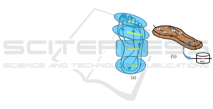
The optical platform is composed of a cork sole, with
1.0 cm thickness, in which POFBG sensors will be
incorporated in critical points of analysis (heel,
midfoot, metatarsal and toe areas, Fig. 1 (a)) to
monitor the plantar pressure (Wearing et al., 1999), as
shown in Fig. 1 (b). The cork sole was then designed
and machined in order to incorporate the network of
5 FBG sensors, which were distributed in the key
points for the plantar pressure analysis (heel, midfoot,
metatarsal and toe areas) (Razak et al., 2012; Tao et
al., 2012), as shown in Fig. 1. The material chosen to
embed the sensors was the cork due to its excellent
properties for this application, namely thermal
isolation, malleability and a near zero Poisson ratio
(Silva et al., 2005).
5 FBGs were inscribed and multiplexed into a
CYTOP polymer optical fiber cable (Thorlabs, 2017)
using point-by-point technique (Theodosiou et al,
2016). In this case, we obtained 4th order gratings
from 600 periods making a total FBG length of 1.2
mm. The FBG´s wavelengths range was from 1530 to
1570 nm according with our interrogation system.
Considering the load pressure applied in the gait
movement, the FBGs were encapsulated in epoxy
resin (Liquid Lens
TM
) cylinders structures (1.0 cm
diameter and 0.5 cm height). Each sensing element
consists of such cylindrical epoxy structure with the
FBG at the middle position.
To compensate any temperature change, an FBG
temperature sensor (Yuan et al., 2012) was
incorporated in the insole, in order to guarantee that
the thermal isolation provided by the cork is
effectively obtained and the FBG plantar pressure
sensors are not affected by the body temperature, or
any external temperature changes.
Figure 1: Schematic representation of: (a) the foot plantar
main areas; (b) physical distance between FBGs in the
CYTOP fiber and the sensors network implemented for the
insole.
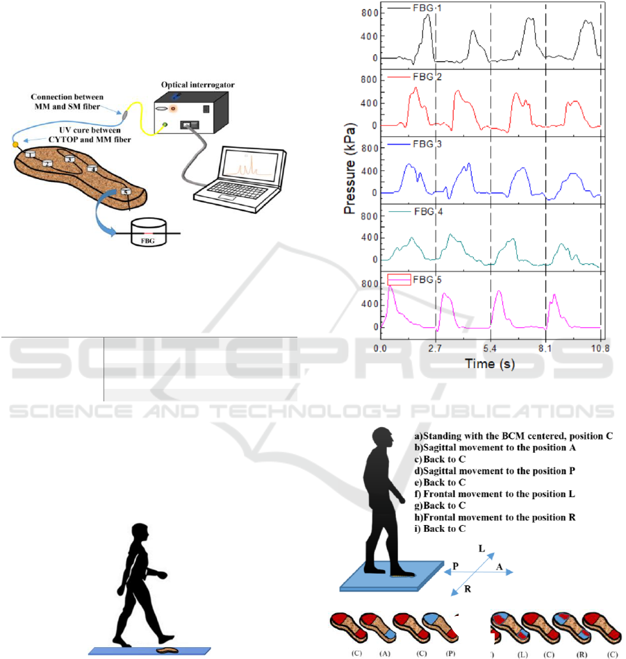
For the calibration and plantar pressure
monitoring, the FBG sensing network was connected
to a portable interrogation system constituted of a
miniaturized broadband optical ASE module (B&A
Technology Co., As4500), an optical circulator
(Thorlabs, 6015-3) and an optical spectrometer
(Ibsen, I-MON 512E-USB). The latter operates at a
maximum rate of 960 Hz, with a wavelength
resolution of 5 pm, responsible for the acquisition of
the Bragg wavelength shift. Fig. 2 shows the fixed
platform monitoring system. To avoid multiple
reflections in the final optical spectra, a multimode
(MM) fiber was connected between CYTOP and
singlemode (SM) fiber before connect to the
interrogation system. The array of 5 FBG sensing
elements were calibrated to different pressure load
BIODEVICES 2018 - 11th International Conference on Biomedical Electronics and Devices
26
values ranging from 10 N up to 150 N. The load sets
were applied independently in each sensing point
(from FBG 1 to FBG 5), using a probe with a diameter
of 10 mm. For these elements, the sensitivity
coefficients achieved were 8.31±0.20 pm/kPa (FBG
1), 7.99±0.28 pm/kPa (FBG 2), 8.51±0.23 pm/kPa
(FBG 3), 7.71±0.31 pm/kPa (FBG 4), and 8.20±0.15
pm/kPa (FBG 5). Table 1 summarizes all sensitivity
coefficients for all CYTOP FBGs.
Figure 2: Schematic representation of the fixed platform
monitoring system.
Table 1: Calibration of the FBG sensors to pressure.
FBG number
Sensitivity (pm/kPa)
1
8.31±0.20
2
7.99±0.28
3
8.51±0.23
4
7.71±0.31
5
8.20±0.15
After the calibration, two sets of studies were
implemented in order to verify the reliability of both
the fixed platform and the insole developed.
The pressure induced in the sensing elements
during a normal gait movement was analyzed with the
platform fixed at the ground, as showed in Fig. 3.
Figure 3: Schematic diagram of the protocol implemented
for gait analysis using the fixed platform.
The response of each sensing element to the
pressure during a gait cycle was repeated and
acquired 4 times. The feedback of the platform to the
displacement of the body center of mass (BCM) was
also evaluated. In Fig. 4, the acquired data is
presented, from which it is possible to verify that the
sensing network response is similar for the 4
passages, confirming the repeatability of the sensor’s
response.
Figure 4: Pressure obtained during the 4 steps and the
resulting curve of all the sensors response sum for each step.
.…
Figure 5: Schematic diagram of the protocol implemented
for the analysis of the BCM displacement; b) descritive
protocol on the foot (the subject remained in each position
for 3 seconds - the pressure on each foot location is colored
to red in the scheme).
The BCM displacements, in the body sagittal and
frontal planes of motion, were also analyzed using the
…..
(a)
(b)
Foot Plantar Pressure Monitoring with CYTOP Bragg Gratings Sensing System
27
same platform. For that purpose, a female subject
with 55 kg, was asked to place her foot on the sensing
platform and to execute a series of BCM movements
(with a ~3 seconds duration each), starting by
standing still with the BCM centered (C), followed by
an anterior (A) position and then back to the original
position (C) from which goes to posterior (P) position
and then resting again at the center (C). After the
sagittal displacement, a frontal displacement was
executed, in which the subject moved the BCM first
to the left (L), back in the center (C) and then to the
right (R), and finally back in the center (C). In Fig. 5,
the implemented protocol is schematized.
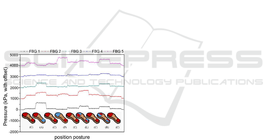
During the protocol implementation, the Bragg
wavelength shift induced in the sensing network was
acquired and the correspondent pressures were
collected. Fig. 6 presents the response of each sensor,
during the different moments of the tests performed.
From the positive feedback of the fixed platform
during the performed tests, it becomes evident that the
method implemented is an adequate solution for
pressure monitoring during gait. Moreover, from the
analysis of the pressures registered during the stance
phase, it is also possible to infer and monitor the
plantar pressures of individuals.
Figure 6: Representation of the pressures detected during
the BCM displacements (the pressure on each foot location
is colored to red in the scheme).
The main advantages obtained with POF
technology when compared with silica fiber
technology (Domingues et al., 2017) are the
following: much higher sensitivity; high flexibility;
easy to handling with fiber when installed to the cork
insole where silica fiber breaks many times due to the
lack of acrylate protection in the fiber after FBGs
inscription.
3 CONCLUSIONS
In this paper, we propose a fiber-optic sensors
network based on CYTOP POFBGs to monitor the
plantar pressure. It has the advantages of a simple
architecture (only using five sensing elements),
relative low cost, temperature insensitivity, high
stability and sensitivity. Moreover, using POF
technology, it also provides the necessary resistance
to be damaged or broken the system during the gait
movement as can easily happen using silica optical
fiber. The measurement of human plantar pressure
distribution, to monitor and understand whether the
foot posture needs to be corrected or not, was
demonstrated in this work. In order to improve the life
quality of physically weakened citizens and increase
the mobility of elder citizens, an integrated “in-shoe”
CYTOP POFBGs sensor network, which is able to
monitor health conditions by observing physiological
parameters in the foot, is in progress using this
technology.
ACKNOWLEDGEMENTS
This work was funded by FCT/MEC through national
funds and when applicable co-funded by FEDER—
PT2020 partnership agreement under the project
UID/EEA/50008/2013. Carlos Marques and Maria F.
Domingues acknowledge the financial support from
FCT through the fellowships SFRH/BPD/109458/
2015 and SFRH/BPD/101372/2014, respectively.
REFERENCES
D. J. Webb, "Fibre Bragg grating sensors in polymer optical
fibres", Measurement Science and Technology 26,
092004 (2015).
F. Bischoff, "Organic polymer biocompatibility and
toxicology", Clinical chemistry 18, 869 (1972).
M. C. J. Large, J. Moran, L. Ye, "The role of viscoelastic
properties in strain testing using microstructured
polymer optical fibres (mPOF)", Measurement Science
and Technology 20, 034014 (2009).
J. G. A. Griffiths, Tables of physical and chemical
constants. By G. W. C. Kaye and T. H. Laby. The
Analyst 73 (1948) 704.
S. Ando, T. Matsuura, S. Sasaki, "Perfluorinated polymers
for optical waveguides", Chemtech 24, 20 (1994).
C. A. F. Marques, D.J. Webb, P. Andre, “Polymer optical
fiber sensors in human life safety, “Optical Fiber
Technology 36, 2017, 144-154 (2017).
A. Razak, A. Hadi, A. Zayegh, R. Begg and Y. Wahab,
“Foot plantar pressure measurement system: A review”,
BIODEVICES 2018 - 11th International Conference on Biomedical Electronics and Devices
28

Sensors 12(7), 9884-9912 (2012).
W. Tao, T. Liu, R. Zheng and H. Feng, “Gait analysis using
wearable sensors”, Sensors 12(2), 2255-2283 (2012).
O. Postolache, J. Pereira, V. Viegas, L. Pedro, P. Girão, R.
Oliveira and G. Postolache, “Smart walker solutions for
physical rehabilitation”, IEEE Instrumentation and
Measurement Magazine 18(5), 21-30 (2015).
L. de Vito, O. Postolache and S. Rapuano, “Measurements
and sensors for motion tracking in motor
rehabilitation”, IEEE Instrumentation and
Measurement Magazine 1(6), 30-38 (2014).
P. Roriz, L. Carvalho, O. Frazão, J. Santos and J. Simões,
“From conventional sensors to fibre optic sensors for
strain and force measurements in biomechanics
applications: A review”, Journal of Biomechanics 4(6),
1251-1261 (2014).
E. Morag and P. R. Cavanagh, "Morag E, Cavanagh PR.
Structural and functional predictors of regional peak
pressures under the foot during walking," Journal of
biomechanics, vol. 32, no. 4, pp. 359-370, 1999.
J. Z. Hao et al., “Design of a foot-pressure monitoring
transducer for diabetic patients based on FBG sensors,”
Lasers and Electro-Optics Society, LEOS 2003, The
16th Annual Meeting of the IEEE, 1 (2003).
T. C. Liang, J. J. Lin, and L. Y. Guo, “Plantar pressure
detection with fiber Bragg gratings sensing system,”
Sensors 16(10), 1766 (2016).
R. Suresh et al., “Development of a high resolution plantar
pressure monitoring pad based on fiber Bragg grating
(FBG) sensors,” Technol Health Care 23(6), 785–794
(2015).
M. F. Domingues, C. Tavares, C. Leitão, A. Frizera-Neto,
N. Alberto, C. Marques, A. Radwan et al. "Insole
optical fiber Bragg grating sensors network for dynamic
vertical force monitoring." Journal of Biomedical
Optics 22, no. 9, pp. 091507-091507, 2017.
S. C. Wearing et al., “A comparison of gait initiation and
termination methods for obtaining plantar foot
pressures,” Gait Posture 10(3), 255–263 (1999).
S. P. Silva et al., “Cork: properties, capabilities and
applications,” Int Mater Rev 50(6), 345–365 (2005).
Thorlabs, “Graded-Index Polymer Optical Fiber (GI-
POF).” [Online]. Disponível: https://www.thorlabs.
com/catalogPages/1100.pdf. [available: 19-Jun-2017].
A Theodosiou, A Lacraz, M Polis, K Kalli, M Tsangari,
“Modified fs-laser inscribed FBG array for rapid mode
shape capture of free-free vibrating beams” IEEE Phot.
Techn. Lett. 28, 1509, (2016)
W. Yuan, A. Stefani, O. Bang, “Tunable polymer Fiber
Bragg Grating (FBG) inscription: Fabrication of dual-
FBG temperature compensated polymer optical fiber
strain sensors,” IEEE Photon. Technol. Lett. 24, 401
(2012).
Foot Plantar Pressure Monitoring with CYTOP Bragg Gratings Sensing System
29
