
Line-based Registration of Photogrammetric Point Clouds with 3D City
Models by Means of Mixed Integer Linear Programming
Steffen Goebbels and Regina Pohle-Fr¨ohlich
Institute for Pattern Recognition, Faculty of Electrical Engineering and Computer Science,
Niederrhein University of Applied Sciences, Reinarzstr. 49, 47805 Krefeld, Germany
Keywords:
Point Cloud Registration, Linear Programming, Structure from Motion, Building Reconstruction, CityGML.
Abstract:
This paper describes a method to align photogrammetric point clouds with CityGML 3D city models. Amongst
others, we use photogrammetric point clouds that are generated from videos taken from the driver’s perspective
of a car. Clouds are computed with the Str ucture-from-Motion algorithm. We detect wall planes to rotate these
clouds so that walls become vertical. This allows us to find buildings’ footprints by accumulating points that
are orthogonally projected to the ground. Thus, the main alignment step can be performed in 2D. To this end,
we match detected footprints with corresponding footprints of CityGML models in a x-y-plane based on line
segments. These line segments are detected using a probabilistic Hough transform. Then we apply a Mixed
Integer Linear Program to find a maximum number of matching line segment pairs. Using a Linear Program,
we optimize a rigid affine transformation to align the lines of these pairs. Finally, we use height information
along CityGML terrain intersection lines to estimate scaling and translation in z-direction. By combining the
results, we obtain an affine mapping that aligns the point cloud wi th the city model. Linear Programming is
not widely applied to registration problems; however the technique presented is a fast alternative to Iterative
Closest Point algorithms t hat align photogrammetric point clouds with clouds sampled from cit y models.
1 INTRODUCTION
Virtual 3D city models are used for simulations (eg
noise maps, lighting models, solar poten tial analy-
zes, flood maps, h e at requireme nt mapping) as well
as for planning purposes like Building Information
Modeling (BIM). CityGML is the XML b ased des-
cription standard for city mode ls. It offers a conc e pt
of Level of Detail (LoD), see (Gr¨oger et al., 2012)
Most models currently are given in LoD 2 with de-
fined roof facets and walls but without detailed fa-
cade informatio n. Window and door objects belong
to LoD 3. Facade models do not only serve for visua-
lization or planning purp oses. For example, gateways
and routes for rescue workers are very interesting in
smart-city applications. Whereas airborne laserscan-
ning point clouds are provided as open da ta in o ur
country, they only show roofs but no facades. Facade
data have to be acquired individually. An inexpensive
way to obtain photog rammetric point clou ds of faca-
des from videos or overlapping photos is to use the
Structure-from-Motion algorithm (SfM).
We generate dense point clouds from videos taken
either through the fron t window of a car or b y UAVs
with the SfM tool Agisoft Photoscan, see Figure 1.
The tool delivers a c loud of colored po ints, estima -
ted camera position and camer a parameters for video
frames, and a textur e d mesh.
It is difficult to do a manual r egistration of pho-
togrammetric point clouds with sufficient precision to
cleanly project points or textured meshes to CityGML
walls. Therefore , we apply an automatic precise re-
gistration of the point cloud with the city model. As
a p reliminary, the cloud has to be coarsely registe-
red with UTM coo rdinates, either manually or using
GPS/GLONASS informatio n. The next section dis-
cusses some approaches to do such a precise registra-
tion. In Sections 3–5 we in detail descr ibe ou r ap-
proach to match line segments by solving a combi-
natorial proble m with fast Linear and Mixed Integer
Linear Program s. Section 6 summarizes results.
2 VARIOUS REGISTRATION
APPROACHES
There exists a large variety of point cloud registration
algorithm s, see (Maiseli et al., 2 017). Most of them
can b e classified as non-feature- or feature-based. Ho-
Goebbels, S. and Pohle-Fröhlich, R.
Line-based Registration of Photogrammetric Point Clouds with 3D City Models by Means of Mixed Integer Linear Programming.
DOI: 10.5220/0006533002990306
In Proceedings of the 13th International Joint Conference on Computer Vision, Imaging and Computer Graphics Theory and Applications (VISIGRAPP 2018) - Volume 4: VISAPP, pages
299-306
ISBN: 978-989-758-290-5
Copyright © 2018 by SCITEPRESS – Science and Technology Publications, Lda. All rights reserved
299

Figure 1: SfM point cloud, and cloud sampled from Ci-
tyGML walls and merged with terrain points from airborne
laserscanning.
wever, our input consist of only one (colored) point
cloud. The city model basically is a set of poly-
gons. The easiest way to apply non- feature-based al-
gorithms is to sample a point cloud from the city mo-
del. We work with 100 points/ m
2
. Experiments sho-
wed that increased sampling rates only do have mi-
nor influence on registration results. In contrast to
simultaneou s loc alization and mapping (SLAM) ap-
plications, the point clouds might be very different:
The photogrammetric point cloud covers ground and
vegetation whereas our city models do no t. With re-
gard to the ground, the problem can be healed by mer-
ging the sampled model cloud with a filtered cloud
from airb orne la serscanning that only consists of last
pulse terrain p oints, see see Figure 1. Another pro-
blem is that buildings ar e modeled separately in Ci-
tyGML. Thus, there exist walls between neighboring
buildings that are not visible from the outside. The-
refore, we only consid e r model walls for sampling if
they are visible from outside the buildings. We also
limit the sampled scene roughly to the area that is co-
vered by the photogrammetric point cloud.
The standard me ans to align point clouds is the
non-feature-ba sed Iterative Closest Point (ICP) algo-
rithm, see (Rusinkiewicz a nd Levoy, 200 1).
We did several experiments with Point
Cloud Library’s ICP implementations (version
1.8.0) in point-to-point and in point-to-plane
mode (see (Holz et al., 2015) and tu torials o n
http://pointclouds.org/documentation/tutorials), both
with a maxim um corresponden c e distance of 5m that
fits with data. Whereas the base implementa tion of
point-to-point ICP migh t converge very slowly or get
stuck in a sub-optimum, ICP based on Levenberg-
Marquar d optimization and poin t-to-plane ICP find
good solution s. In p oint-to-plain mode, distances
are not measured between points but betwe en points
and planes defined by estimated local normal vectors
(see (Chen and Medioni, 1992)). This allows for
sliding along wall planes and is better suited to
match segments of planes like facades. Whereas the
Levenberg-Mar quard based point-to-point algor ithm
takes 4507 seconds
1
to align the clouds shown in
Figure 1, poin t-to-plane I CP finishes in 719 seconds.
However, our proposed method terminates in less
than 30 seconds (see St. Anton street scenario in
Ta ble 1).
A somewhat related approach is the Normal Dis-
tribution Transform (NDT). Its idea is to replace all
cloud points within a grid cell of the target cloud by
a normal distribution that describes the probability of
finding a point at a certain po sition. Instead of ma-
tching single points to each other, the probability of
points being at the right place (with regard to the tar-
get cloud) can be optimized with Newton iterations,
see (Magnusson et al., 2009). This technique elimina-
tes the time of ICP’s ne arest neighbor search. With a
resolution pa rameter set to 5 an d a step size parame-
ter set to 2.5 Point Cloud L ibrary’s algorithm aligns
the two previously investigated clo uds in 3 96 seconds.
For chosen settings, this indeed is faster than ICP in
point-to-plane mode but still significant slower than
our proposed method. In our scenario, success and
running time of NDT heavily depend on choice of
parameters. For examp le, the method converges to
a wrong alignment for step size 3 but converges to the
correct global optimu m for step sizes 1, 2.5, a nd 5 .
For clouds of structured environments, examples
of (Ma et al., 2016) show that there might be problems
with iterative non-feature- based methods. Such pro-
blems occur if clouds overlap only partially or initial
coarse alignment is bad. Also, runn ing times strongly
depend on cloud size and parameters. Another dis-
advantage is that we need additional in formation like
digital terrain mode ls to en rich sampled clouds.
In our scenarios, walls are dominant structures
and reference surfaces are very simple. Therefore,
we concentrate on pairing spe c ific geometric primiti-
ves as do most feature-based registration methods (cf.
(Chuang and Jaw, 2015)). One could directly detect
plane segments that represent walls and align them
with CityGML wall po lygons. However, both de-
tected segments and CityGML polygo ns are only ap-
proxim ations of real walls. Also CityGML polygons
are simplified due to their level of detail. But most
CityGML models use high quality building footprints
from cadastral data. Therefore, we work with walls’
footpr ints. Based on RANSAC estimates of wall pla-
nes, we rotate the point cloud so that walls become
straightened up and ground is oriented parallel to the
x-y-plane . By or thogonally projecting points to the x-
y-plane, walls become visible as dense contours. This
1
Running times are measured on a single core of a
2.4GHz i5 processor (2013) with 4GB RAM.
VISAPP 2018 - International Conference on Computer Vision Theory and Applications
300
basically simplifies the 3D alignment problem to a 2D
task of aligning these contours with CityG ML buil-
ding footprints. The RANSAC-based rotation step is
similar to the use of angle-f e atures in the general pur-
pose point cloud alignm e nt algorithm of (Ma et al.,
2016). They compute a rotation matrix based on an
angle histogram. Rotation leads to translation of the
histogram that, for example, can be detected using the
Fourier transform shift property
2
. However, angle-
features become disturbed if d ifferent scaling factors
are used for different coordin ate directions du ring co-
arse registration. This also is a problem if one tries to
detect rotation between 2D footprint images based on
an angle histogram of Hough lines. In our scenario,
Hough space registration (cf. (Zhao, 2006)) additio-
nally suffers from different lengths of line segments.
Established alignment proc edures for 2D ima ges
mostly avoid to solve an NP-complete combinatorial
optimization problem. But footprint images of point
clouds and city models are quite different so that com-
binatorial o ptimization promises to deliver results that
are more r obust against distortions. We investiga-
ted combinatorial alignment procedures based on cor-
ners of footprints, based on line segments of foot-
prints and based on straight lines covering line seg-
ments. For UAV po int clouds covering larger urban
areas, corner-based alignment works well if there are
sufficient many building corners (of different height)
in a scene. In our experiments, we detected building
corners using Harris corner detector and aligned them
with vertices of the city model using a Mixed Integer
Linear Program (MIP) similar to the one in Section
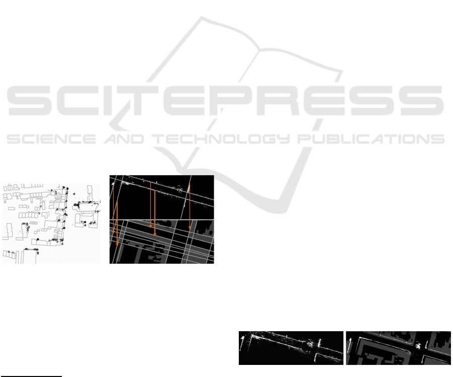
4, see Figure 2. Unfo rtunately, the videos that we use
Figure 2: Left: Corner-based matching of building walls
detected from a UAV point cloud (see Section 6) with Ci-
tyGML model’s walls. Right: L ines that are detected in the
point cloud are matched with CityGML model lines.
for facade detec tion mostly are taken from street level.
They cover more detail, and corner detection does not
only find significant building corners but also corners
of smaller structures. Also, in a straight street with
2
Sarvaiya, J., Patnaik, S., and Kothari K.: Feature Ba-
sed Image Registration Using Hough Transform. http://
psrcentre.org/images/extraimages/48.%2050.pdf (Accessed
07 July 2017)
few intersections, th e number of significant corners is
small. Therefore, our implemen ta tion of corner based
matching does not work well with this type of point
clouds. Instead, straight lines of building footprints
are significant. Line-based matching ap proaches have
been used successfully to align images with digital
surface mo dels a nd air borne laserscanning data, see
for example (Avbelj et al., 2 013; Cui et al., 2017).
They have been also used to align two p oint clouds,
see for example (Li et al., 2012). One can either
match unbounded straight lines or the short bounded
line segments that are part o f footprints. There might
be several line segments appr oximately lying on the
same straight unbounded line. Thus joining line seg-
ments to u nbounded lines reduces the number of pos-
sible matching comb inations. Whereas match ing o f
unbounded straight lines works for simple street sce-
narios (cf. Figure 2), it might fail for complex UAV
point clouds that lead to a variety of similar lines.
Therefore, we propose to match line segments (cf.
Figure 4). Where as (Avbelj et al., 2013) use a sta-
tistical, accumu lator based approach to match lines,
(Li et al., 2012) present an iteration sch e me and (Cui
et al., 2017) apply non-linear least-squa res optimiza -
tion, we u se a simpler Mixed Integer Linear Program
to find matching line segmen t pa irs in combination
with a Linear Program (LP) to compute a 2D trans-
formation matrix. However, this requires pre- and
post-processing steps that u tilize the vertical nature
of walls.
3 PRE-PROCESSING
First, we both translate photogrammetric cloud and
city model into a local coo rdinate system with orig in
at −
~
t ∈ R
3
to avoid large numerical erro rs: Th e cor-
respond ing translation is given by
T =
E
~
t
(0,0,0) 1
∈ R
4×4
with un ity matrix E ∈ R
3×3
. Then we rotate the pho -
togrammetric cloud to correctly align with the z-axis
and generate a 2D building footprint ima ge a s fol-
lows:
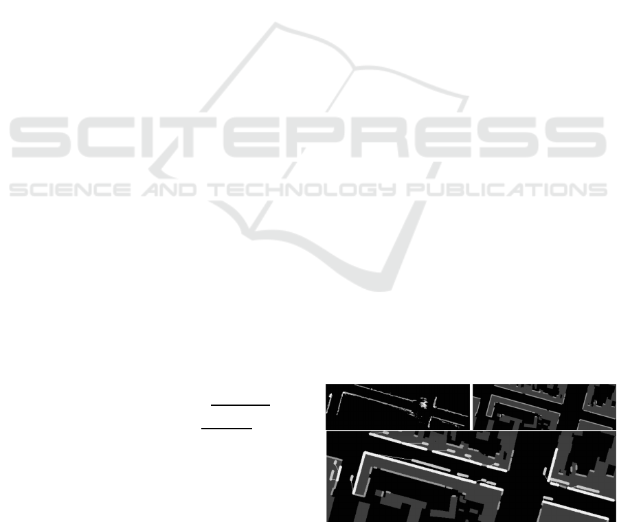
Figure 3: Density of point cloud and binary image of likely
wall footprints superposed with CityGML building foot-
prints.
Line-based Registration of Photogrammetric Point Clouds with 3D City Models by Means of Mixed Integer Linear Programming
301
• To generate a preliminary binary image of li-
kely wall footprints, a resolution of 9 pixels per
square meter is sufficient for ou r data, see Fi-
gure 3 . We compute minimum and maximum z-
coordinates (height values) of all points with x-
and y-coord inates within the p ixel’s area. If these
values at least differ 3.5 m in height (one building
level) and if the re exist at least eight points with
z-coordinates pairwise belonging to disjoint inter-
vals of width 0.5m then we classify the pixel as
being part of a wall footpr int. One could also
generate a density image by counting the po ints
above the pixel’s area. Then thresho lding cou ld
give a wall map. Unfor tunately, we work with
point clouds of very different local densities so
that it is difficult to find or generate a suitable
threshold value.
• Walls might not be exactly vertical. Before we re -
duce the cloud to wall and ground points, we have
to rotate it with a matrix D to make walls upright.
To this end, we divide the ground into 10 m ×10 m
sections. For each section we iteratively apply a
RANSAC algorithm to the section’s subset of the
cloud that also corre sponds roughly with previ-
ously comp uted p ixels o f wall footprints. With
RANSAC we estimate nearly vertical planes for
each section. We collect th e nor mal vectors of
the third of planes with largest number of inliers.
Let N be the set of these normals. We estimate
the common upward-direction of all walls with a
RANSAC algorithm as well: We iteratively select
a plane through the origin and through two non-
collinear points in N. Out of all selected planes
we choose one with the largest n umber of inliers
p, p ∈ N. The n we apply a rotation D,
D =
cos(β) −sin(β)sin(α) − sin(β)cos(α) 0
0 cos(α) −sin(α) 0
sin(β) cos(β)sin(α) cos(β)cos(α) 0
0 0 0 1
,
to the point cloud that aligns this plane’s normal
vector (n.x,n.y,n.z), n.z > 0, with the z-axis. Let
h = sin(α) · n.y + cos(α) · n.z. Angles are
α = sign(n.y)arccos(n.z/
p
n.y
2
+ n.z
2
),
β = sign(n.x)arccos(h/
p
n.x
2
+ h
2
).
The appr oach requires the existence of walls with
different orientations.
• Now we compute a sharper version of the binary
wall footprint image. Since walls should exactly
point upwards after applying D, we can reduce
noise by filtering for even larger height differen-
ces ( 5m instead of 3 .5m) to detect walls.
Our goal is to match the footprint image with a si-
milar image that we obta in from the city model. To
this end, we draw a single picture of filled footprints
of a ll CityGML buildings, on ly considering the area
of the photogrammetric point cloud. Then we detect
edges with the Can ny operator. These edges corr e-
spond with facades but not with walls between hou-
ses.
Both on the footprint image and on the edge pic-
ture, we apply a probabilistic Hough transform to de-
tect line segments, see Figure 4. In the f ollowing
section we use the sets P and Q that contain line seg-
ments of the footprint image and the model’s edg e
picture, respectively.
4 LINEAR PROGRAMS
Linear and Mixed Integer Linear Programming have
been used for registration purpo ses, see for exam-
ple (Sakakubara et al., 2007; Wang et al., 2017).
However, most alignment procedures u se n on-linear
optimization. Linear optimization isn’t even listed
amongst the optimization methods for point cloud
alignment in the overview article (Tam et al., 2013) .
But if one seeks for a linear or affine transformation
and if one is allowed to measure er rors in l
1
-norm
(sum of abso lute values) instead of the wid e ly used
l
2
-norm (least squares) then Linear Progra mming is a
very powerful tool. MIP and LP also have been consi-
dered for the generation of CityGML models and 3D
modeling. For example, (Boulch et al., 2014) use a
MIP to reconstruct surfaces from point clouds.
The difficulty of our r egistration task is that we
have to select from a candidate set of line pairs
before we can compute a linear tr a nsformatio n to
align line segments of P with line segments of
Q. Let P = {(p
1,1
, p
1,2
),... , (p
m,1
, p
m,2
)} and Q =
{(q
1,1
,q
1,2
),... , (q
n,1
,q
n,2
)}. Each line segment is de-
fined by its two endpoints that are given in homogen e -
ous coordinates, for example p
i,k
= (p
i,k
.x, p
i,k
.y,1)
⊤
.
Figure 4: First two pictures: Detected line segments of point
cloud and CityGML model; third picture: Matching line
segments are connected with thin bright lines.
VISAPP 2018 - International Conference on Computer Vision Theory and Applications
302

Now we have to determine a linear tran sform L
that align s the largest possible subset of P with a cor-
respond ing subset of Q by u sin g translation, scaling
and rotation as feasible operatio ns.
A common method to find large correspondin g
sets of line features is to use RANSAC in Hough
space. For example, (Colleu et al., 2 008) use this ap-
proach to match video fr ames with city model data. In
contrast to this we match bounded line segments with
a M IP that automatically also c omputes an initial ver-
sion of the transf ormation matrix.
First, w e have to find matching candidate pairs
between P and Q. If a binary variable x
i, j
, 1 ≤
i ≤ m, 1 ≤ j ≤ n, equals one, then the pair
((p
i,1
, p
i,2
),(q
j,1
,q
j,2
)) is selected for matching. It is
not selected if x
i, j
= 0. We can a-priori exclude pairs
by setting their bina ry variables fixed to z e ro. We do
this if their lines have a distance in Hough space above
a threshold value. Also, we compute a bounding bo x
for each line segment and extend it by the expected
error of coarse alignment. If bounding boxes of two
line segments do not inter sect th en we also exclude
the pair. This is the sole step in our alignment method
that might cause it to only find a local but no global
optimum . In contrast to ICP and other non-feature-
based algorithms, what follows describes global op ti-
mization.
We have to maximize an objective function like
m
∑
i=1
n
∑
j=1
x
i, j
(1)
subject to the restriction that there is a linear mapping
L =
s
1
cos(α) −s
1
sin(α) d
1
s
2
sin(α) s
2
cos(α) d
2
0 0 1
∈ R
3×3
that approximately maps line of segment (p
i,1
, p
i,2
)
onto line of (q
j,1
,q
j,2
) if x
i, j
= 1. Manual coarse re-
gistration should be done so that scaling s
1
in x- and
scaling s
2
in y- direction is equal: s := s
1
= s
2
. Then
there is less uncertainty and more stability.
There need to exist scalars r
1,i, j
and r
2,i, j
such that
for k ∈ {1,2} and
d
+
k,i, j
− d
−
k,i, j
:= q
j,1
+ r
k,i, j
(q
j,2
− q
j,1
) − Lp
i,k
(2)
there ho lds true 0 ≤ d
±
k,i, j
.x ≤ ε, 0 ≤ d
±
k,i, j
.y ≤ ε.
Thus, the co ordinate- w ise distance between tr a nsfor-
med points Lp
i,1
, Lp
i,2
and the straight line through
q
j,1
and q
j,2
has to be bounded by a fixed threshold
value ε. We work with ε := 0.5 for selection of candi-
date pairs (distanc e s will be further minimized in a se-
cond optimization step). The source line segment has
to be approximately mapped onto a straight line going
through the target line segment. There is no need to
actually hit the target segment. This allows for sli-
ding like in ICP p oint-to-plane mode. Nevertheless,
we match segments and not straight lines because we
a-prior i exclude pairs (i, j) of distant segments by set-
ting x
i, j
= 0.
To obtain a linear pr oblem, we do no t compute
sine and cosine functions but seek for a ma trix
L =
l
1,1
l
1,2
l
1,3
l
2,1
l
2,2
l
2,3
0 0 1
under restrictions
l
1,1
= l
2,2
,
l
1,2
= −l
2,1
if s
1
= s
2
, (3)
−µ ≤ l
1,1
− l
2,2
≤ µ,
−µ ≤ l
1,2
+ l
2,1
≤ µ
if s
1
6= s
2
, (4)
1 − δ ≤ l
1,1
≤ 1 + δ, −δ ≤ l
1,2
≤ δ, (5)
where δ = 0.3 and µ = 0.1 are small threshold values.
These restrictions avoid that L describ es mirroring .
Instead of using simple objective function (1) we
consider the le ngths of point cloud line segments as
weights. Let w
i
be th e length o f the i-th point cloud
line segment. We extend the objective function to
∑
m
i=1
∑
n
j=1
w
i
x
i, j
. Maximizatio n favors selection of
long line segments.
We write the optimization problem as an Integer
Linear Program with the help of a large number M.
M is used to restrict the distance condition to selected
pairs of line segments while keeping the problem li-
near. Let distances d
+
k,i, j
, d
−
k,i, j
∈ (R
≥0
)
3
and matrix
coefficients l
r,c
∈ R, 1 ≤ r ≤ 2, 1 ≤ c ≤ 3:
Max.
m
∑
i=1
n
∑
j=1
w
i
x
i, j
s.t.
m
∑
i=1
x
i, j
≤ 1 for 1 ≤ j ≤ n,
n
∑
j=1
x
i, j
≤ 1 for 1 ≤ i ≤ m,
conditions (2) and (( 3) or (4)) and (5), and
max{d
+
k,i, j
.x,d
+
k,i, j
.y,d
−
k,i, j
.x,d
−
k,i, j
.y} + Mx
i, j
≤ ε+ M.
A MIP in genera l is NP complete. It very much
depends on the number of candidate corresponden-
ces and on the size of ε how long a solver takes to
find a solution. We use the GNU Linear Programming
Kit library GLPK (Makhorin, 2009) to solve LPs and
MIPs. I n most scenarios of this pap e r, solutions of
the MIPs are found in less than a second. Neverthe-
less, running times can be decreased. It turns out that
the exclusion of distant line segments from the mat-
ching task allows f or an LP relaxation of the MIP. In
the relaxed problem, binary variables x
i, j
are repla-
ced by real-valued variables x
i, j
∈ [0, 1]. It turns out
Line-based Registration of Photogrammetric Point Clouds with 3D City Models by Means of Mixed Integer Linear Programming
303
that values of x
i, j
become indeed very close either to
zero or to one. We then round th em. The tr adeoff of
relaxation is that one has to deal with a few wrong
matchings during the following second optimization
step that improves the mapping L:
Based on an optimal solution of the MIP, we de-
fine the set R of pairs (i, j) for which x
i, j
= 1 so that
for all (i, j) ∈ R distan ces fulfill 0 ≤ d
±
k,i, j
.x,d
±
k,i, j
.y ≤
ε. To further minimize the errors, we apply another
LP. By u sin g the same variable names as for the MIP,
this LP h a s to minimize
∑
(i, j)∈R
2
∑
k=1
w
i
(d
+
k,i, j
.x + d
+
k,i, j
.y + d
−
k,i, j
.x + d
−
k,i, j
.y)
subject to (2) for (i, j) ∈ R, and conditions (3) or ( 4),
and (5).
Weights w
i
now enforce large line segments to be
matched with higher precision than short ones.
Based on L, we can align the poin t cloud in the
x-y-plane using m a trix
A :=
l
1,1
l
1,2
0 l
1,3
l
2,1
l
2,2
0 l
2,3
0 0 1 0
0 0 0 1
.
5 POST-PROCESSING
It remains to estimate an ad ditional z-scaling factor
and a z-translation . To this end, we look at te rrain in-
tersection points of CityGML models. For each such
point, we have a true z-value z
g
of the ground and also
determine the height z
r
of th e roof ab ove this point.
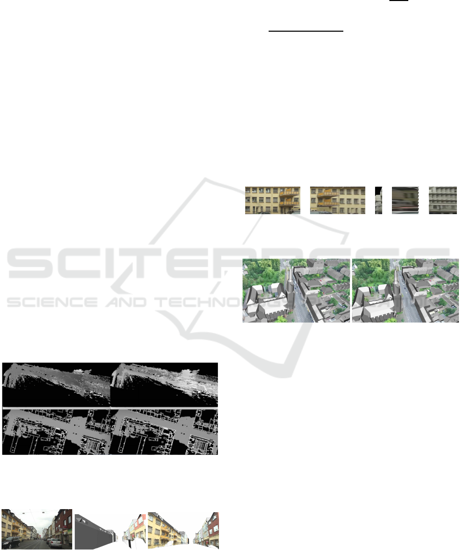
Figure 5: Height maps showing minimum and maximum
values of adjusted photogrammetric point cloud and sam-
pled model cloud
Figure 6: A video frame used for point cloud generation,
projection of point cloud onto city model prior to alignment,
and projection of aligned point cloud onto city model.
We also determ ine a corresponding lowest and hig -
hest point of the pre-proc essed point c loud that has
been tr ansformed with A, see Figure 5. Let z
l
and z
h
be the z-coordinates of these two points, respectively.
Then we get a local z-scalin g factor
z
r
−z
g
z
h
−z
l
. If the same
scaling factor was applied to all directions during ma-
nual coarse registration, z-scaling factor should be
s =
p
l
1,1
· l
2,2
− l
1,2
· l
2,1
. We allow a small deviation
by considering all local scaling factors within the in-
terval [s − 0.2,s + 0.2 ]. To avoid outliers, we compute
the median value z
s
of these feasible local scaling fac-
tors. Using z
s
we determine the z-translation value z
t
as the media n of all lo c al translation values z
g
− z
l
·z
s
.
Then we finally align the cloud with the city mo del by
multiplying its points with
T
−1
ZADT, Z :=
1 0 0 0
0 1 0 0
0 0 z
s
0
0 0 0 z
t
.
Figure 7: Perspective projection of video frame areas onto
CityGML walls.
Figure 8: A city model is drawn onto a video frame using
the frame’s SfM camera transformation and estimated ca-
mera projection. The upper picture is based on a course
manual alignment between SfM point cloud and UTM coor-
dinate system. The second picture shows optimized align-
ment.
After aligning the point cloud with the city model,
we c an match model walls with areas in video frames
or orthogonally p roject points to walls, see Figures 6
and 7. Fortunately, the SfM tool provides camera pa-
rameters and, in a bundle output file, for each frame
k ∈ {1,... , n} a translation vector
~
t
k
∈ R
3
and a rota-
tion ma trix R
k
∈ R
3×3
that tog e ther de fine a transfor-
mation C
k
of the orig inal, non-aligne d photogramme-
tric cloud into the frame’s camera coordinate system:
C
k
:=
R
k
~
t
k
(0,0,0) 1
.
After applying this mapping, the camera’s position is
the o rigin and the camera looks into the d irection of
the negative z-axis. We multiply the photogramme-
tric point cloud with matrix T
−1
ZADT to align with
VISAPP 2018 - International Conference on Computer Vision Theory and Applications
304

the city model. Thus, the transform a tion of the c ity
model into the camera’s coordinate system is given
via m a trix C
k
(T
−1
ZADT )
−1
= C
k
T
−1
D
−1
A
−1
Z
−1
T .
We can now ren der the model using cam e ra para me-
ters so that it exactly fits with the came ra frame ( see
Figure 8 for the UAV city center scenario that is des-
cribed in Section 6). Vice versa, CityGML walls can
be textured either based on the point cloud (Figure 6),
or based on the corresp onding textured mesh or based
on single vide o fra mes (Figure 7).
6 RESULTS
We apply the algorithm to three different point clouds.
So far, we h ave used a dense point cloud (now deno-
ted as St. Anton street) a s example. The point clo ud
of Knight street (see Figure 9) also is taken throug h
the front window o f a car, but it is much thinner than
the one of St. Anton street. The third clo ud (see Fi-
gure 10) originates from a UAV video of a city center.
This scenario also allows for alignment by matchin g
corners, see Figure 2. To visualize transformations,
we worsened coa rse manual registration by shifting
the clouds by 4 mete rs in x- and y-directions, respec ti-
vely. Table 1 an d Figures 9 and 10 summarize r esults
of comp utation.
Precision of the registration co rresponds with re-
solution 1/3 meter of the pictures used to detect wall
lines. It can be slightly impr oved by increasing pictu-
res’ resolution. However, if the resolution is too high,
it becomes difficult to detect walls.
To investigate the lim its of our algorithm, we align
sampled model point clouds with transf ormed versi-
ons of them selves in a local coordinate system. These
small clouds are free of noise and lead to a high num-
ber of correspondences. Th is increases running time
of our MIP optimization step whereas such clouds
are simple to ma tc h for ICP in point-to-plane mode.
For example, our algorithm takes 82 seconds to (ap-
proxim ately) undo the transfor mation B
−1
(rotations
by 0.01 degrees around all axes, scaling factor 0.99
and translation with (−4,−4,4)) applied to the mo-
del cloud of Figure 1. It computes a matrix
˜
B that is
a good approximation of ground truth ma trix B. In
compariso n, ICP in point-to-plane mode
3
converges
to a corresponding ma trix
ˆ
B in 89 seconds. In this ex-
ample, ou r algorithm finds 136 candid a te pairs of cor-
respond ing line segments. The single MIP step runs
67 seconds. If we do not compute the exact solution
of the MIP but use a solution of the relaxed MIP th e n
3
Point Cloud Library’s class IterativeClosestPointWith-
Normals is used with parameters TransformationEpsilon =
10
−8
and EuclidianFitnessEpsilon = 0.1.
Table 1: Three i nvestigated scenarios.
St. Anton Knight UAV city
street street scenario
number of points 8.593.746 1.995.498 5.017.262
line segments of point cloud 114 71 68
line segments of city model 61 73 338
candidate pairs of line 71 95 56
segments
pairs selected by relaxa tion 24 24 24
of MIP
pairs selected by MIP 17 20 21
model vertices used for 32 48 33
z-operations
running time pre-processing 14s < 4s < 1s
running time MIP a nd LP < 1s < 1s < 1s
running time post-processing 15s 6s 2s
overall running time decreases to 14 seco nds and the
optimization steps finish in less than a second w ith
outcome matrix
˜
˜
B. The overall ru nning tim e can be
further decreased by limiting the number of RANSAC
plane estimates in th e pre-processing step.
Figure 9: Knight street scenario: matching between line
segments, thin point cloud, points projected to model walls.
Figure 10: Left: UAV point cloud and points projected to
model walls. Right: matching between line segments.
The l
2
-vector norm is defined via k(a
1
,... ,a
n
)k
2
:=
q
a
2
1
+ ·· · + a
2
n
, and the l
2
-matrix (spectral) norm
kB −
˜
Bk
2
:= sup
k(B −
˜
B) ·~ak
2
k~ak
2
:
~
0 6=~a ∈ R
4
is a mea sure for the quality of the c omputed align ment
mapping
˜
B. Let ~v ∈ R
3
be a point of the cloud and
~e = (e.x,e.y, e.z) ∈ R
3
the difference between the cor-
Line-based Registration of Photogrammetric Point Clouds with 3D City Models by Means of Mixed Integer Linear Programming
305

rectly and ap proximately aligned versions of ~v. Then
k(e.x,e.y,e.z,0)k
2
=
(B −
˜
B)· (v.x,v.y,v.z,1)
⊤
2
≤ kB −
˜
Bk
2
q
k~vk
2
2
+ 1.
Our non-re la xed algorithm aligns best with kB −
˜
Bk
2
≈ 0.1407 in the current scenario, f ollowed by
the relaxed version (kB −
˜
˜
Bk
2
≈ 0.2069) an d b y ICP
(kB −
ˆ
Bk
2
≈ 0.288).
7 CONCLUSIONS
One can utilize the vertical orientation of walls to re-
duce the problem of aligning photogrammetric point
clouds with 3D city models to two space dimensi-
ons if at least two wall segments with linear inde-
pendent directions are detected. This might be given
if the scene covers an intersectio n of stree ts. Th en,
instead of ICP, featur e-based alignment using Linear
Programming is a suitable means. Useful results
are obtained by matching line segments of wall foot-
prints. While the algorithm is designed to align with
city models, it can also be used to align two poin t
clouds in which walls are dominant. Although not
so fast, the point-to-plane version of ICP also aligns
well with sampled CityGM L models.
REFERENCES
Avbelj, J., Iwaszczuk, D., M¨uller, R., Reinartz, P., and
Stilla, U. (2013). L ine-based registration of DSM and
hyperspectral images. ISPRS - International Archives
of the Photogrammetry, Remote Sensing and Spatial
Information Sciences, XL-1/W1:13–18.
Boulch, A., de La Gorce, M., and Marlet, R. (2014).
Piecewise-planar 3D reconstruction with edge and
corner regularization. Computer Graphics Formum,
33(5):55–64.
Chen, Y. and Medioni, G. (1992). Object modelling by re-
gistration of multiple range images. Image and Vision
Computing, 10(3):145–155.
Chuang, T.-Y. and Jaw, J.-J. (2015). Automated 3D feature
matching. The Photogrammetric Record, 30(149):8–
29.
Colleu, T., Sourimant, G., and Morin, L. (2008). Automa-
tic initialization for the registration of GIS and video
data. In Proc. 2008 3DTV Conference: The True Vi-
sion - Capture, Transmission and Display of 3D Video,
pages 49–52, Washington, DC. IEEE.
Cui, T., Ji, S., Shan, J., Gong, J. , and Liu, K. (2017). Line-
based registration of panoramic images and lidar point
clouds for mobile mapping. Sensors, 17(1).
Gr¨oger, G., Kolbe, T. H., Nagel, C., and H¨afele, K. H.
(2012). OpenGIS City Geography Markup Language
(CityGML) Encoding Standard. Version 2.0.0. Open
Geospatial Consortium.
Holz, D., Ichim, A. E., Tombari, F. , Rusu, R. B., and
Behnke, S. (2015). Registration with the point cloud
library: A modular framework for aligning in 3-D.
IEEE Robotics Automation Magazine, 22(4):110–124.
Li, W., Li, X., Bian, Y., and Zhao, H. (2012). Multiple view
point cloud registration based on 3D lines. In Proc.
International Conference on Image Processing, Com-
puter Vision, and Pattern Recognition (IPCV), pages
1–5.
Ma, Y., Guo, Y., Zhao, J., Lu, M., Zhang, J., and Wan, J.
(2016). Fast and accurate registration of structured
point clouds with small overlaps. In 2016 IEEE Con-
ference on Computer Vision and Pattern Recognition
Workshops (CVPRW), pages 643–651.
Magnusson, M., N¨uchter, A., L¨orken, C., Lilienthal, A. J.,
and Hertzberg, J. (2009). Evaluation of 3D regis-
tration reliability and speed — a comparison of ICP
and NDT. In Proc. IEEE International Conference on
Robotics and Automation (ICRA), pages 3907–3912,
Washington, DC. IEEE.
Maiseli, B., Gu, Y., and Gao, H. (2017). Recent deve-
lopments and trends in point set registration methods.
Journal of Visual Communication and Image Repre-
sentation, 46:95–106.
Makhorin, A. (2009). The GNU Linear Programming Kit
(GLPK). F ree Software Foundation, Boston, MA.
Rusinkiewicz, S. and Levoy, M. (2001). Efficient variants of
the ICP algorithm. In Proc. Third International Con-
ference on 3-D Digital Imaging and Modeling, pages
145–152.
Sakakubara, S., Kounoike, Y., Shinano, Y., and Shimizu,
I. (2007). Automatic range i mage registration using
mixed integer linear programming. In Yagi, Y., Kang,
S. B., Kweon, I. S., and Zha, H., editors, Proc. 8th
Asian Conference on Computer Vision, Tokyo 2007,
Part II, pages 424–434, Berlin. Springer.
Tam, G. K., Cheng, Z .-Q., Lai, Y.-K., Langbein, F. C., Liu,
Y., Marshall, D., Martin, R. R., Sun, X.-F., and Rosin,
P. L. (2013). Registration of 3D point clouds and mes-
hes: A survey from rigid to non-rigid. IEEE Trans.
Visualization and Computer Graphics, 19(7):1–20.
Wang, Y., Moreno-Centeno, E., and Ding, Y. (2017).
Matching misaligned two-resolution metrology data.
IEEE Transactions on Automation Science and Engi-
neering, 14(1):222–237.
Zhao, S. (2006). Hough-domain image registration by me-
taheuristics. In Proc. 9th International Conference on
Control, Automation, Robotics and Vision 2006, pages
1–5.
VISAPP 2018 - International Conference on Computer Vision Theory and Applications
306
