
Optical-inertial Synchronization of MoCap Suit with Single Camera
Setup for Reliable Position Tracking
Adam Rie
ˇ
cick
´
y
2,4
, Martin Madaras
1,2,4
, Michal Piovar
ˇ
ci
3,4
and Roman
ˇ
Durikovi
ˇ
c
2
1
Institute of Software Technology and Interactive Systems, University of Technology, Vienna, Austria
2
Department of Applied Informatics, Comenius University, Bratislava, Slovakia
3
Saarland University, MMCI Saarbr
¨
ucken, Germany
4
Skeletex Research, Bratislava, Slovakia
Keywords:
Motion Capture, Inertial Suit, Optical System, Optical-inertial Synchronization, Silhouette Tracking.
Abstract:
We propose a method for synchronization of an inertial motion capture suit and a single camera optical setup.
Proposed synchronization is based on an iterative optimization of an energy potential in image space, mini-
mizing the error between the camera image and a rendered virtual representation of the scene. For each frame,
an input skeleton pose from the mocap suit is used to render a silhouette of a subject. Moreover, the local
neighborhood around the last known position is searched by matching the silhouette to the distance transform
representation of the camera image based on Chamfer matching. Using the combination of the camera tracking
and the inertial motion capture suit, it is possible to retrieve the position of the joints that are hidden from the
camera view. Moreover, it is possible to capture the position even if it cannot be captured by the suit sensors.
Our system can be used for both real-time tracking and off-line post-processing of already captured mocap
data.
1 INTRODUCTION
Considering the problem of person tracking and
movement analysis, there are a lot of motion capture
(mocap) solutions available in both academia and in-
dustry. Mocap is a widely used technique for storing
and processing movement data of the person. A reli-
able motion capture and tracking is necessary in the
film and games industry, virtual reality, biometrics or
even healthcare. Optical-based tracking is more prob-
lematic in the tracking area if it has occlusions. More-
over, the tracking area might be very non-convex, and
therefore non-coverable by optical-based mocap and
tracking systems. In such a case, it is suitable to
use non-optical methods for tracking; however, some
other limitations appear, such as drifting, calibration
and synchronization problems or additional noise in
the captured data. Sometimes, these limitations are
solved by a post-processing of raw data using com-
plex probabilistic models that have to be trained on
reliable training datasets, which might be impossible
to obtain in a given situation.
Nowadays, there are a variety of mocap systems
suitable for recording of the body movements. There
are two major groups of mocap systems, optical-
based and inertial-based systems. Each group has its
own advantages and limitations. The advantages of
inertial systems are the flexible capture area (outdoor
capture, water capture), occlusion independence, fast
setup time, transferability and the possibility of direct
use of the raw output data for a 3D model. The biggest
disadvantage is that one can get only rotation data of
each skeleton joint. The joint positions in 3D space
have to be calculated based on the calibration process
and the root position estimation, which have to be ap-
proximated by a walking algorithm implemented in
the mocap software. On the other hand, the optical
systems are limited to indoor use only. They have
problems with occlusions and cannot directly return
the information about the joint rotation around the
bone axis. The individual joint position can be tracked
easily; however, the rotations need to be calculated in
the next evaluation stage. In order to solve the posi-
tioning disadvantage of inertial systems, solutions us-
ing radio/NFER or ultrasound positioning have been
proposed. However, these systems are in general hard
to calibrate and synchronize.
Furthermore, in our project, we need to obtain
reliable position tracking of the inertial suit using a
commodity RGB camera. The whole system should
40
Rie
ˇ
cický, A., Madaras, M., Piovarci, M. and Durikovic, R.
Optical-inertial Synchronization of MoCap Suit with Single Camera Setup for Reliable Position Tracking.
DOI: 10.5220/0006531100400047
In Proceedings of the 13th International Joint Conference on Computer Vision, Imaging and Computer Graphics Theory and Applications (VISIGRAPP 2018) - Volume 1: GRAPP, pages
40-47
ISBN: 978-989-758-287-5
Copyright © 2018 by SCITEPRESS – Science and Technology Publications, Lda. All rights reserved

be affordable and it should be compatible with both
outdoor and indoor usage.
Therefore, in our project we propose a hybrid
optical-inertial system. In this system, the mocap in-
ertial suit is combined and synchronized with a single
camera. Once the camera is calibrated and the rela-
tive position and orientation are calculated, it can be
used for real-time effortless position estimation. The
hybrid system does not require a training phase and
has advantages over both optical and inertial motion
capture systems. Other hybrid tracking systems need
either a complicated setup or are much more expen-
sive. Our system requires only an inertial suit and a
single RGB camera.
2 RELATED WORK
Inertial Suits. There are several inertial IMU suits
available on the market: a 3DSuit by Inertial Labs, an
IGS Cobra suit by Synertial, an MVN suit by XSens
and a Perception Neuron suit by Noitom. The suits
differ in sensor configuration, price and precision. For
example, the suits from XSens and Synertial have a
higher number of sensors and can stream raw data for
all the sensors. The Perception Neuron suit is a cheap
and affordable solution for the general public, with a
smaller set of sensors. Afterwards, the streamed data
available to the reader are interpolated from the raw
sensor data.
Optical Mocap. Optical systems can be divided
into two main groups: systems based on passive retro-
reflective or active markers, and marker-less mocap
systems that are trained on a set of training images.
The marker-based systems are able to perform
with much higher accuracy. In practice, optical sys-
tems and suits with markers are used, e.g. OptiTrack,
Vicon. A group of multi-view RGB-only-based mo-
cap systems working without a training stage exists,
using shape from silhouette or sums of spatial Gaus-
sians (Cheung et al., 2003; Stoll et al., 2011). These
optical systems usually need a complicated setup and
multiple cameras.
The trained probabilistic marker-less techniques
(Wojek et al., 2009; Andriluka et al., 2010) that work
on RGB images are not very precise in general. Thus,
they are typically used for academic research testing
only, or they have to be fused with inertial sensors as
in (Pons-Moll et al., 2010). Lately, a helmet with two
fisheye RGB cameras was proposed in (Rhodin et al.,
2017) for the motion capture of a subject wearing the
helmet. The system can only capture motion of the
skeleton; this cannot be used for position tracking.
Probabilistic optical approaches can be trained di-
rectly on depth values obtained by an RGBD camera,
for example Kinect. The Kinect is mostly used for
real-time pose estimation (Shotton et al., 2013). This
probabilistic skeleton estimation is not very precise,
but is well suited for the fun real-time applications
where Kinect tracking is mostly used. Moreover, the
Kinect can be used for both real-time skeleton estima-
tion and surface reconstruction using Kinect Fusion
(Izadi et al., 2011). Depth values from the RGBD
camera can be used for point cloud reconstruction
and the skeleton can be extracted from a point cloud.
However, this process is too slow for real-time mo-
tion capture. Nevertheless, it can be used for body
size estimation and calibration from a single scan.
These data can be used to improve motion capture
data (Anguelov et al., 2005).
Moreover, the probabilistic optical-based systems
are trained on RGB or RGBD images and estimate
position in 3D space based on probabilistic models
(Shotton et al., 2013; Andriluka et al., 2010). An op-
tical flow based on Chamfer matching can be used to
track the subject without a training stage (Dimitrijevic
et al., 2006; Katz and Aghajan, 2008). These methods
can be used directly on the input frames; however, a
background subtraction is a necessary preprocessing
step to obtain robust tracking results.
An extensive comparison of inertial and optical-
based motion capture suits can be found in (Skogstad
et al., 2011).
Person Tracking. Similarly, as in the case of mocap
solutions, the tracking can be optical based or approx-
imated using triangulation of distances to the signal
source, e.g. GPS. The lighthouse tracking by Valve
is part of HTC Vive and it is based on a measuring
of time delay between emitting a flash and sweeping
a beam of light across the room. The receivers cal-
culate the time delay between these two light flashes
and using a simple trigonometry the 3D position of
the receiver can be evaluated in real-time.
Hybrid Systems. Several hybrid approaches were
published in recent years. The hybrid systems for
skeleton and position tracking are based on a fusion
of the IMU orientation data and some other sensor. In
(Ziegler et al., 2011), the subject in an inertial suit is
tracked by a robot with a laser scanner. Such a combi-
nation can track the subject’s position and trajectory
in big areas; however, it might be impossible to use
the robot in small interiors and the robot is too expen-
sive tool for common usage. A fusion of multi-view
RGB cameras with few IMUs was proposed in (Pons-
Moll et al., 2010; von Marcard et al., 2016). These
Optical-inertial Synchronization of MoCap Suit with Single Camera Setup for Reliable Position Tracking
41
approaches for fusion give very good results; how-
ever, the fusion needs a scanned template model of
the subject and the system needs multiple RGB cam-
eras in order to correctly fit the template into the sil-
houette. A combination of discriminative and gener-
ative tracking using a depth sensor was used in (Hel-
ten et al., 2013). The approach also needs a template
mesh model and the RGBD camera has a very lim-
ited volume where the fusion works precisely enough.
In general, the mentioned related hybrid approaches
either need a much more complicated and expensive
setup (multiple cameras, depth camera, robot), or they
have a much more complex tracking pipeline than our
approach (template mesh scanning, non-linear energy
minimization, training stage).
3 OPTICAL-INERTIAL
SYNCHRONIZATION
The main idea behind the optical-inertial tracking so-
lution of the suit and the camera is determining the 3D
position of the actor from his silhouette in the camera
image based on his actual pose. Knowing the actor’s
skeleton pose from the suit in real-time, we are able to
predict the body shape we are looking for within the
camera image. First, a base mesh is constructed using
the actor’s specific parameters such as height or lo-
cal diameters. This mesh is then used for rendering a
shape which is similar to the actor’s silhouette in the
image. A virtual camera which is used for the base
mesh rendering needs to see the scene the same way
as a real camera sees the scene with actor; therefore,
it needs to be calibrated.
The rendered base mesh silhouette is then used to
search the local neighborhood of the last known po-
sition of the subject in the next image frame. Min-
imizing the energy composed of spatial integration
of Chamfer matching error in the image space, we
are able to perform real-time tracking of the subject.
During the tracking, a 3D virtual scene is rendered
and matched to the camera image; therefore, if it is
matched with the precisely calibrated camera setup,
we are able to directly estimate the 3D position of the
subject in the real world.
3.1 System Overview
The whole tracking system is composed of three
phases: a calibration phase, a tracking start-up phase
and an iterative tracking phase. The first two phases
are used for the initial setup only to determine and to
correctly represent the real world in the tracking sys-
tem; therefore, the third phase is the actual tracking
stage.
The calibration phase needs to be done only once,
or when the camera is replaced. This step is required
to acquire correct camera parameters. The parameters
can be saved and reused before each tracking session.
The second stage, the tracking start-up phase,
needs to be performed at least once before each ses-
sion, to synchronize the real-world camera with the
virtual camera of a system, and to specify the actor’s
starting location for the tracking. However, there is a
possibility to assign these properties during the itera-
tive tracking phase, seamlessly without the interrup-
tion of the tracking procedure.
Finally, the tracking phase is iteratively performed
during the whole remaining tracking time. Output of
this stage is the true 3D position of the actor in both,
the virtual scene and the real world.
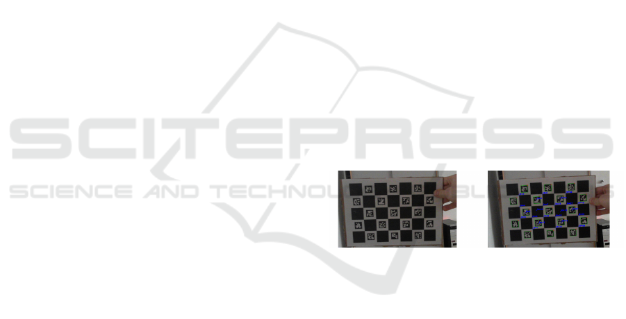
3.2 Initial Setup and Calibration
For the camera calibration, an OpenCV with its built-
in modules is used. We used the ChArUco module
that uses a hybrid checkerboard for both camera cali-
bration and camera position estimation, as can be seen
in Figure 1. Given several pairs of point correspon-
dences of calibration patterns in the real world and
in the image space, it is possible to find intrinsic and
extrinsic parameters of the camera.
Figure 1: The ChArUco calibration board. The ChArUco is
a combination of the classical calibration checkerboard and
the ChArUco alphabet signs.
Next, the body size of the actor needs be measured
manually using a ruler, or in an automatic way using
a Kinect or calibrated RGB camera. The measured
body height and body radii are then used together with
the mocap position to construct a base mesh approxi-
mating the body of the subject.
3.3 Virtual Scene Creation
The main idea behind the synchronization is to create
a virtual scene according to the parameters acquired
in the real world. This step is called the tracking start-
up phase, and it must be generally executed before
each tracking session, when some scene properties are
changed, e.g. camera is moved, camera is changed,
starting position is changed, etc.
GRAPP 2018 - International Conference on Computer Graphics Theory and Applications
42
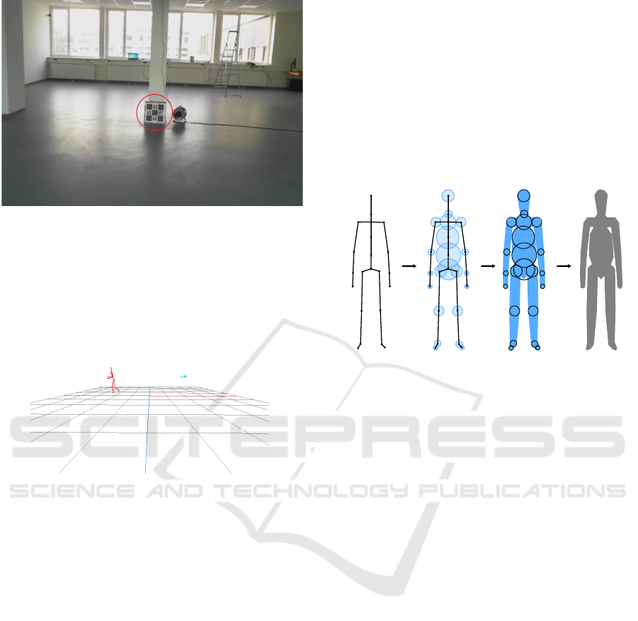
Figure 2: A model-view matrix that consists of a rotation
and a translation of the ChArUco board into the camera im-
age is obtained in the tracking start-up phase. Thus, the
origin of the virtual scene is set into the ChArUco board
location and the camera position and orientation are set ac-
cordingly.
Figure 3: A virtual scene is constructed based on the camera
calibration, calculated scene parameters and current mocap
data. Using either the real-time mocap data or stored off-
line mocap data, a silhouette of the tracked subject is ap-
proximated and later used during the tracking phase.
In order to get the origin of the virtual space, a
ChArUco board marker (see Figure 2) is placed in
front of the camera. As an input it takes correspond-
ing points together with board parameters and as an
output it produces the rotation and translation trans-
formations that give us a model-view matrix of the
checkerboard in world space coordinates. Having the
ChArUco marker detected, we are able to estimate the
camera position and orientation relative to the origin.
The second purpose of placing a ChArUco board into
the scene is to define the starting position of the ac-
tor (the actor starts in the origin of the virtual scene).
This is the position where the tracking starts. The
precision of the tracked position relies deeply on the
camera calibration and proper virtual scene setup (see
Figure 3). If the ChArUco board cannot be used for
some reason, the starting position and camera param-
eters can be always set manually.
3.4 Silhouette Image Database
Construction
The camera image contains objects and subjects
which are not important for the system. The goal of
the system is to locate and track only the actor dressed
in the motion capture suit. Therefore, the pose data
from the suit are used to determine this. The reader of
the suit rotations is able to stream local transforma-
tions for each frame in real-time.
Figure 4: A base mesh is created using the skeleton acquired
from the mocap suit. The skeleton is enhanced with mea-
sured radii of the actor’s body. Note that the base mesh
construction process is depicted in 2D only.
Firstly, a shape that roughly represents the actor’s
body is needed. Here, it might be possible to use a
broad set of shapes, from primitives roughly approxi-
mating the body to a high-detailed 3D scan. However,
we choose to create a simple base mesh approximat-
ing the body shape mesh from the input skeleton, be-
cause it is easily customizable, scalable and can be
generated in real-time for any skeleton pose. For this
a SQM algorithm (Bærentzen et al., 2012) is used,
which is able to generate such a mesh specifying only
the skeleton and the radius of a sphere around each
skeleton node (see Figure 4). These radii as well as
skeleton height are dependant on the actor’s body type
and need to be measured or approximated manually.
Such a specific base mesh is generated only once, and
a pose for every frame is created by applying rotations
from suit sensors and transforming the base mesh ac-
cordingly using a skinning algorithm.
With the virtual camera and scene created and suc-
cessfully calibrated, it is possible to render an image
of the base mesh as if it was seen by a real camera.
Afterwards, this image is processed to obtain only
the silhouette of a rendered image. Finally, a set of
silhouette images is rendered, applying several shifts
of a base mesh in eight evenly distributed directional
vectors. Our set consists of images shifted k times by
d in a space around a specified pose as well as one im-
age of a base mesh exactly in the current position, as
Optical-inertial Synchronization of MoCap Suit with Single Camera Setup for Reliable Position Tracking
43
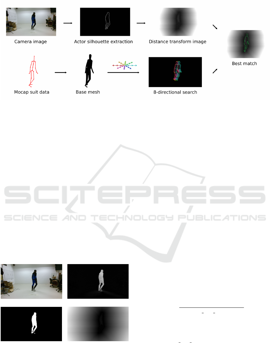
Figure 5: The pipeline of our optical-inertial synchronization. (Top) the camera image is thresholded and transformed into a
distance transform image. (Bottom) a base mesh is constructed based on the acquired skeleton and it is rendered in different
positions. The base of 8 search vectors is used to render 8 shifted silhouettes. The Chamfer matching of the rendered base
mesh and the distance transform image is performed, and the error is evaluated. Finally, the error minimization is used to find
the next position in 3D space.
can be seen in Figure 5. In our experiments, we used
constants d = 10cm and k = 3; therefore, in total a set
of 25 images is rendered and stored in the silhouette
database.
3.5 Tracking
The tracking phase begins after the tracking start-up
phase was executed successfully, which properly sets
up a camera for rendering the base mesh silhouette
database. An actor is located in a specified position
defined by the ChArUco board placed in the scene.
At this point, the tracking phase is ready to start. This
start-up position is considered to be the actor’s true
position in the first frame. For each next frame, a mo-
tion vector is evaluated to evaluate the actor’s next
position.
Figure 6: Tracking of the actor position using Chamfer
matching. (Top) an input image and the subtracted back-
ground image in grayscale. (Bottom) applied adaptive
thresholding and calculated distance transform of the sil-
houette.
First, the captured camera image is pre-processed us-
ing background subtraction, thresholded and Canny
edge detection is performed so that only the actor’s
silhouette is obtained. Then, the image is transformed
into a distance transform image (see Figure 6). Af-
terwards, the already pre-rendered database of base
mesh silhouette images is used to evaluate the energy
e for the optimization. The error potential e is calcu-
lated for each silhouette as an integration of the dis-
tance transform function DT(x) over the actor silhou-
ette S as
e
k
=
ZZ
S
DT (x(s, t))dsdt, (1)
where parameters s and t are the parameters of the
one-dimensional silhouette curve and a kernel func-
tion that is applied over the curve to make the silhou-
ette wider, respectively. The term x(s, t) is a func-
tion that maps parameters s and t to the image space,
where function DT (x) is evaluated. The integration
in discrete form is performed in the image space as a
sum of non zero pixels from silhouette image S
k
and
normalized afterwards as
e
k
=
∑
m
i=0
∑
n
j=0
DT (i, j) · S
k
(i, j)
count non zero(S
k
)
, (2)
where (i, j) refers to a pixel position of the image with
dimensions m × n, DT is the distance transform im-
age, S
k
is the binary silhouette mask image and the
function count non zero() returns a number of non
zero pixels contained in the image. Minimizing the
error energy, we are able to evaluate the direction and
the magnitude of the subject’s movement based on the
shift vectors used for the construction of a database
image. Adding such a vector to the position of an ac-
tor in the last frame, we are able to evaluate the actor
GRAPP 2018 - International Conference on Computer Graphics Theory and Applications
44
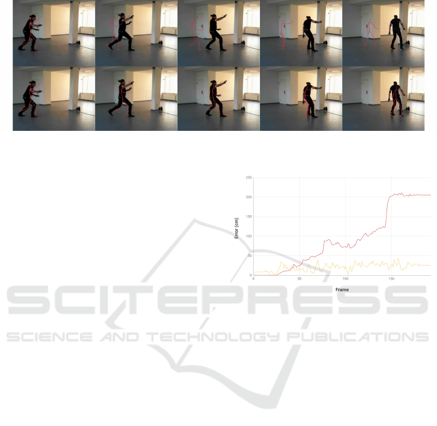
Figure 7: Comparison of XSens MVN tracking (top) and our optical-inertial evaluation (bottom). In the second frame, the
sliding starts and the mocap system fails to evaluate the position correctly. Images were captured using a Microsoft LifeCam
HD 3000 RGB webcam.
position in the current frame. In the end of the track-
ing phase, we have a raw corrected 3D position of the
actor. The pipeline of the system until this point can
be seen in Figure 5. To enhance the raw data, some
suitable post-processing method might be used.
3.6 Post-processing via Gaussian
Filtering
The change of estimated position of the subject in
time might not be continuous. Thus, it is useful
to post-process the discontinuities into a continu-
ous movement. In our experiments we have tried
two methods of post-processing: a Gaussian-based
smoothing and Kalman filtering. We used local Gaus-
sian smoothing in the neighborhood of 20 time steps
and the Extended Kalman Filter (EKT) (Julier and
Uhlmann, 2004) implemented in OpenCV. Using the
EKT filtering, the resulting graphs seem visually
smoother, but the overall error was higher. Therefore,
in the final results, the Gaussian smoothing was used
(see Figure 9).
4 RESULTS
We demonstrate the results of our approach on captur-
ing the motion and estimating the position of a sub-
ject in a space. The subject wears an XSens suit and
the scene is captured using a Microsoft LifeCam HD
3000 RGB webcam and iDS 3 uEye monochromatic
camera with a fisheye lens.
4.1 Correction of Mocap Suit Data
First, the position in 3D space is approximated using
the standard walking algorithm usually implemented
Figure 8: Comparison of error difference in Euclidean dis-
tance between the methods and ground truth obtained us-
ing HTC Vive: (Red) original position from inertial suit
software and (yellow) our optical-inertial method. Graph
is evaluated on a dataset, where the movement was the most
problematic for the original method (e.g. jumping, sliding).
within the mocap software. In this scenario, the ac-
tor starts to run and finishes the running sequence
by sliding on the ground. The sliding is the stage,
where the inertial mocap suit fails. We use the posi-
tion estimated by XSens MVN Studio and export it
into a bvh file. Second, the position is evaluated using
our optical-inertial system. Both estimated positions,
from the original method and our camera-based cor-
rection, can be seen in Figure 7.
4.2 Evaluation of Estimated Position
In order to evaluate our method by comparing re-
sults to the ground truth, we evaluate our correction
of position inside a known environment for move-
ment in predefined patterns (see Figure 11). Dur-
ing this evaluation, the subject moves along the de-
fined trajectories with known dimensions. During
the evaluation we track three position estimations in
time. The subject is tracked by HTC Vive lighthouses
(ground truth), and position estimation is done by
Optical-inertial Synchronization of MoCap Suit with Single Camera Setup for Reliable Position Tracking
45
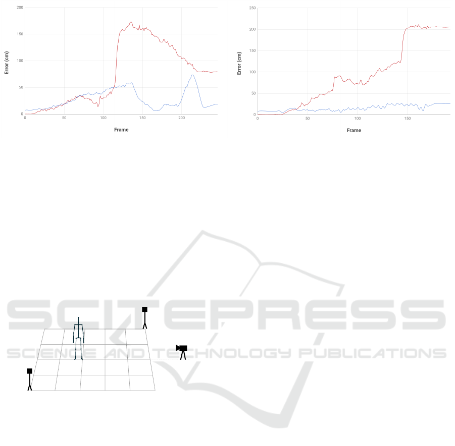
Figure 9: Comparison of error difference with filtered data: (Red) position calculated by original inertial suit software and
(blue) post-processed versions of estimated positions using our approach. Another example from the datasets is plotted on
the right. In both cases, the smoothed versions of evaluated positions approximate the movement and the real position of the
subject much better.
MVN XSens Studio and our optical-inertial estima-
tion. Comparison of the error difference in Euclidean
distance of the original position from the MVN XSens
Studio and our approach can be seen in Figure 8. Fur-
thermore, we tried to smooth the raw results from our
approach; the graphs with the smoothed positions of
two different datasets are shown in Figure 9. In Fig-
ure 10, the setup used for the evaluation is depicted
and described.
A
B
2
B
1
C
Figure 10: The evaluation setup. The subject wearing a
mocap suit (C) is captured by a camera (A) and tracked by
HTC Vive lighthouses (B). The position estimated by the
lighthouses is used as a ground truth when the original mo-
cap suit tracking is compared to the proposed method.
5 LIMITATIONS
The main limitation of the proposed solution is the de-
pendency on the static background subtraction; thus
we are not able to guarantee robust tracking in scenes
with a dynamically changing background. In the case
of background changes, there are edges in the image
space not related to the actor that may drive the track-
ing into a local minimum. Another limitation of the
system is the predefined set of search directions that
produces discretizetion errors. If required, the search
space could be sampled more densely at the cost of
higher computation time. The rendered base mesh
is only a rough approximation of the human body; a
highly detailed full-body scan could be used for bet-
ter approximation of the silhouette. However, the base
mesh is easy to compute, affordable to acquire and the
results are good enough for our applications.
6 CONCLUSION AND FUTURE
WORK
A system for optical-inertial synchronization of the
mocap suit and the camera was implemented and de-
scribed in this paper. In general, the system can find
its utilization in applications such as virtual reality,
movement analysis, sports evaluation, and biometrics.
Using a hybrid mocap system, drift issues of inertial
suits can be solved. Moreover, the lack of positioning
capability of inertial mocap was solved, and therefore
it can be directly used for subject movement analy-
sis in 3D space, ergonomic work analysis process or
virtual reality games. The inertial-optical hybrid sys-
tem is capable of measuring a subject’s position with
high precision even if partially or fully occluded, and
all the computations can be performed in real-time.
These results show promising improvement for iner-
tial suit position tracking, but more extensive evalua-
tion is required in the future.
As future work we would like to use the system for
an automatic and effortless recalibration of the suit.
The correct position and orientation of the joints, eval-
uated from the camera image, can be used for on-line
correction of suit sensors.
ACKNOWLEDGMENTS
We would like to thank the SAIA Action Austria-
Slovakia for financial support of the project and the
GRAPP 2018 - International Conference on Computer Graphics Theory and Applications
46
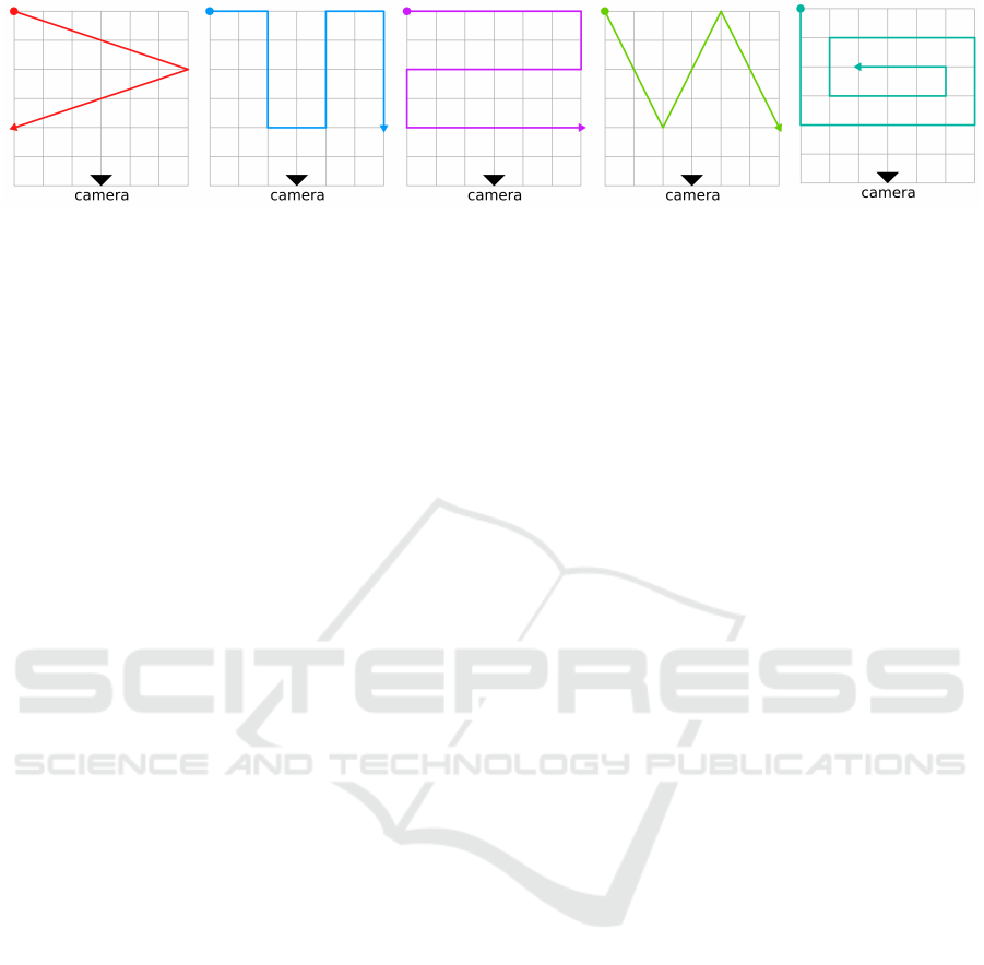
Figure 11: Evaluation of our method on different trajectories within a grid. The grid has a size of 6 × 6 meters. The patterns
were chosen to fully cover the tracking area in different directions. Moreover, different types of movement were used during
the evaluation, such as walking, jumping, sliding etc.
Interactive Media Systems group at TU Wien for all
the necessary hardware and laboratory space during
the project. Our project was also partly supported by
Comenius University grant No. UK/293/2017.
REFERENCES
Andriluka, M., Roth, S., and Schiele, B. (2010). Monocular
3d pose estimation and tracking by detection. In 2010
IEEE Computer Society Conference on Computer Vi-
sion and Pattern Recognition, pages 623–630.
Anguelov, D., Srinivasan, P., Koller, D., Thrun, S., Rodgers,
J., and Davis, J. (2005). Scape: Shape completion and
animation of people. ACM Trans. Graph., 24(3):408–
416.
Bærentzen, J., Misztal, M., and Wełnicka, K. (2012). Con-
verting skeletal structures to quad dominant meshes.
Computers & Graphics, 36(5):555 – 561. Shape Mod-
eling International (SMI) Conference 2012.
Cheung, G. K. M., Baker, S., and Kanade, T. (2003). Shape-
from-silhouette of articulated objects and its use for
human body kinematics estimation and motion cap-
ture. In Proceedings of the 2003 IEEE Computer
Society Conference on Computer Vision and Pattern
Recognition, CVPR’03, pages 77–84, Washington,
DC, USA. IEEE Computer Society.
Dimitrijevic, M., Lepetit, V., and Fua, P. (2006). Human
body pose detection using Bayesian spatio-temporal
templates. Comput. Vis. Image Underst., 104(2):127–
139.
Helten, T., Muller, M., Seidel, H.-P., and Theobalt, C.
(2013). Real-time body tracking with one depth cam-
era and inertial sensors. In The IEEE International
Conference on Computer Vision (ICCV).
Izadi, S., Kim, D., Hilliges, O., Molyneaux, D., Newcombe,
R., Kohli, P., Shotton, J., Hodges, S., Freeman, D.,
Davison, A., and Fitzgibbon, A. (2011). Kinectfu-
sion: Real-time 3d reconstruction and interaction us-
ing a moving depth camera. In Proceedings of the
24th Annual ACM Symposium on User Interface Soft-
ware and Technology, UIST ’11, pages 559–568, New
York, NY, USA. ACM.
Julier, S. J. and Uhlmann, J. K. (2004). Unscented filtering
and nonlinear estimation. Proceedings of the IEEE,
92(3):401–422.
Katz, I. and Aghajan, H. (2008). Multiple camera-based
chamfer matching for pedestrian detection. In 2008
Second ACM/IEEE International Conference on Dis-
tributed Smart Cameras, pages 1–5.
Pons-Moll, G., Baak, A., Helten, T., M
¨
uller, M., Seidel, H.-
P., and Rosenhahn, B. (2010). Multisensor-fusion for
3d full-body human motion capture. In IEEE Con-
ference on Computer Vision and Pattern Recognition
(CVPR).
Rhodin, H., Richardt, C., Casas, D., Insafutdinov, E.,
Shafiei, M., Seidel, H., Schiele, B., and Theobalt,
C. (2017). Egocap: Egocentric marker-less motion
capture with two fisheye cameras (extended abstract).
CoRR, abs/1701.00142.
Shotton, J., Sharp, T., Kipman, A., Fitzgibbon, A., Finoc-
chio, M., Blake, A., Cook, M., and Moore, R. (2013).
Real-time human pose recognition in parts from single
depth images. Commun. ACM, 56(1):116–124.
Skogstad, S. A., Nymoen, K., and Hvin, M. (2011). Com-
paring inertial and optical mocap technologies for
synthesis control. In 2011 IEEE Conference on Sys-
tems, Man and Cybernetics.
Stoll, C., Hasler, N., Gall, J., Seidel, H.-P., and Theobalt, C.
(2011). Fast articulated motion tracking using a sums
of gaussians body model. In Computer Vision (ICCV),
2011 IEEE International Conference on, pages 951–
958. IEEE.
von Marcard, T., Pons-Moll, G., and Rosenhahn, B. (2016).
Human pose estimation from video and imus. Trans-
actions on Pattern Analysis and Machine Intelligence,
38(8):1533–1547.
Wojek, C., Walk, S., and Schiele, B. (2009). Multi-cue on-
board pedestrian detection. In 2009 IEEE Conference
on Computer Vision and Pattern Recognition, pages
794–801.
Ziegler, J., Kretzschmar, H., Stachniss, C., Grisetti, G., and
Burgard, W. (2011). Accurate human motion capture
in large areas by combining imu- and laser-based peo-
ple tracking. In IROS, pages 86–91. IEEE.
Optical-inertial Synchronization of MoCap Suit with Single Camera Setup for Reliable Position Tracking
47
