
SheetAnim - From Model Sheets to 2D Hand-drawn Character
Animation
Heena Gupta and Parag Chaudhuri
Department of Computer Science and Engineering, IIT Bombay, Mumbai, India
Keywords:
2D Character Animation, Sketch-based Animation, Hand Drawn Animation.
Abstract:
We present an intuitive method to create 2D hand-drawn character animation suitable for novice animators.
Given the 2D model sheet of the character that shows how the character looks from the front and side, our
method can generate sketched views of the character from any direction, using the sketch stroke style used in
the model sheet. Subsequently, our system can generate an animation of the character using motion capture
data, and render it using the same sketched strokes. Our method is not only able to reproduce the sketch stroke
style, but also the colours and other character details that the animator adds to the model sheet. The method
can resolve occlusion correctly, both due to moving body parts and change in orientation of the character with
respect to the camera. The animator can interactively change the sketch style, colours or other details, at any
frame, as required. The animation generated by our method has the fluid style of hand sketched animation, and
provides a very good starting point for novice animators that can be then improved to create the final, desired
animation.
1 INTRODUCTION
Hand-drawn character animation is a beautiful art
form. It offers the animator unique expressive free-
dom in creating characters. However, it requires a
significant amount of skill and effort on the part of
an animator to create. Not only is it difficult to con-
vincingly sketch a character in different poses from
different view directions, it is even harder to do this
while maintaining rhythm and temporal coherence.
Many researchers have attempted to develop
methods and tools to aid and simplify the creation
of 2D character animation (Jones et al., 2015; Xing
et al., 2015; Patel et al., 2016). However, most of
these are restricted in the kind of interaction they al-
low the animator to have with the character and the
resulting animation that they can generate. Many of
these methods cannot handle changing orientations of
the character with respect to the camera position dur-
ing the animation, and thus, cannot also handle the
occlusions that result from such motion. Also, some
of them cannot preserve the style of sketching of the
animator.
Our method allows the animator to intuitively and
easily generate animation from a character model
sheet and also preserves the sketch style and colours
present in the model sheet. If the model sheet shows
the character from a front and a side view, then our
method can generate sketched views of the character
for any camera angle. Thereafter, given any motion
data for the character, we can generate an animation
of the character performing the same motion, even if
the relative orientation of the character with respect to
the camera changes during the motion of the charac-
ter.
Our system is especially suited for novice anima-
tors. They can easily start from the animation that our
system generates and refine it so that it becomes more
visually appealing. Our system is very intuitive and
easy to use, but it also allows the animator complete
freedom to change, edit and update the suggestions
given by the system, if the animator so desires.
An example of the kind of output produced by our
system can be seen in Figure 1. Our method relies
on a background template mesh that is registered to
the character sketch given in the model sheet. The
template mesh is posed and deformed to match the
sketches in pose and shape. Thereafter, any additional
element drawn on the model sheet, like the sunglasses
or the smile as seen in the coloured model sheet in
Figure 1, are correctly reproduced by our method in
the desired animation. The animation motion is gen-
erated based on input motion data.
We start by discussing relevant related work in
Section 2. We follow this up by an overview of our
entire method in Section 3. We then discuss the de-
Gupta, H. and Chaudhuri, P.
SheetAnim - From Model Sheets to 2D Hand-drawn Character Animation.
DOI: 10.5220/0006514100170027
In Proceedings of the 13th International Joint Conference on Computer Vision, Imaging and Computer Graphics Theory and Applications (VISIGRAPP 2018) - Volume 1: GRAPP, pages
17-27
ISBN: 978-989-758-287-5
Copyright © 2018 by SCITEPRESS – Science and Technology Publications, Lda. All rights reserved
17
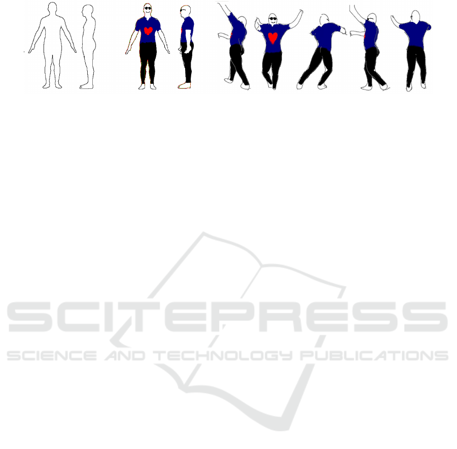
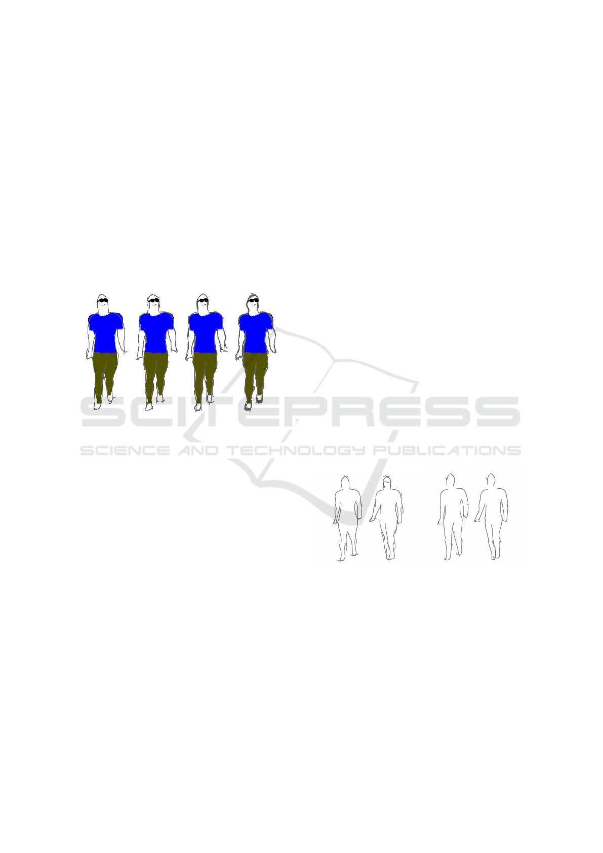
Figure 1: Given a model sheet of a character, an animator can colour the character and add accessories to the character like
sunglasses. Our method generates an animation of the character, according to given motion data. Here frames from a dance
animation are shown. The colors, sketch style and accessories are correctly reproduced by our method in each frame.
tails of template mesh to sketch registration in Sec-
tion 4, and animation generation in Section 5. We
explain ways in which we can enhance the animation
in Section 6. We present frames from multiple result
animations generated by our method in Section 7 and
we conclude with a discussion of limitations of our
system and future work in Sections 8 and 9.
2 BACKGROUND
Creating 2D character animations has attracted the at-
tention of a lot of researchers. Sketch-based interfaces
for creating animation have been used to create char-
acter animation of stick figures (Davis et al., 2003),
doodle paths along which characters can move and
perform actions based on path shape (Thorne et al.,
2004) or create three dimensional animations (Jain
et al., 2009). Some research has also been done to aid
various aspects of animation like storyboarding (Hen-
rikson et al., 2016). Very good results for char-
acter modelling from sketches were recently shown
by (Bessmeltsev et al., 2015). Their method gener-
ates the character geometry from the sketch and a very
well fitting skeleton. It uses a strong assumption of
rotational cross-sectional symmetry at every point on
the contours to generate the model. We believe our
method based on template fitting is more generic and
can handle more body types.
NPR rendering of animated characters has also
been tried in literature (Kalnins et al., 2002; Kalnins
et al., 2003). These systems support sketching di-
rectly on the mesh to stylize its appearance. In us-
ing our system the user never needs to know about
the 3D proxy mesh and never needs to sketch on a
3D surface, which is harder to do. Recent work has
also looked at consistent paint stroke renderings of
3D models (Bassett et al., 2013), and video styliza-
tions (Ben-Zvi et al., 2016). We actively help the an-
imator in creating the animation from a model sheet
and do not restrict the animator to a particular sketch-
ing or motion style.
In other literature, there has been some attempt to-
ward actually aiding the 2D character animation cre-
ation process. Xing et al. (Xing et al., 2015) present
a method to auto-complete hand-drawn animations.
This work can predict future frames of an anima-
tion based on the current and previous frames. It can
also assist the animator by automatically transporting
colour and texture information across frames. How-
ever, this method cannot handle out of plane motions
for the character, i.e., it cannot predict a future frame
when the relationship between the character and cam-
era changes. It can also not handle occlusions cor-
rectly. Another recent work, Tracemove (Patel et al.,
2016) can predict future frames of a 2D character an-
imation from partially sketched frames based on a
matches found in a pose image database and motion
capture data. It is also restricted to handling poses
whose camera positions match those present in the
image pose database, and it cannot change during an
animation. Other methods have attempted to rapidly
create animations by cloning texture sprites (Jones
et al., 2015), however, these cannot support animation
in general.
In order to handle varying orientations of the char-
acter, we register a template mesh to the sketch. We
match the shape and pose of the mesh to the sketch
of the character as given in the model sheet. We
are inspired by the method presented in (Zhou et al.,
2010) to reshape the mesh and register it with the
sketch of the character. Grasp and Taylor (Grasp
and Taylor, 2000) and Kraevoy et al. (Kraevoy et al.,
2009) present methods to recover pose of the charac-
ter from sketches. Levi and Gotsman (Levi and Gots-
man, 2013) present Arti-Sketch, that recovers pose
and shape in one framework from 3 views of the char-
acter. There are, of course, many other works that use
sketches for modelling (Igarashi et al., 1999; Henrik-
son et al., 2016) objects and characters. We base our
method of mesh-sketch registration on this body of
literature and implement a robust scheme that lets us
design a system that is easy and intuitive for the ani-
mator to use.
GRAPP 2018 - International Conference on Computer Graphics Theory and Applications
18

The registered mesh serves as a background proxy
for the sketch and allows us to copy the sketching
and colouring style of the animator from the model
sheet and use it to create the resulting animation. The
idea of mimicking sketching style has been explored
in several works (Hertzmann et al., 2002; Xing et al.,
2015; Magnenat et al., 2015). We are able to perform
this in the presence of unstructured sketching styles
and changing camera views. We were motivated in
this direction by the use of 3D proxy meshes to en-
hance production quality 2D animation in Disney’s
Paperman (Whited et al., 2012).
3 OVERVIEW
Our method allows an animator to create a 2D char-
acter animation from a model sheet. Given a model
sheet, we register the character in the model sheet to
a template mesh. We use a standard template mesh
from the MakeHuman (MakeHuman, 2016) project
for this purpose. We first match the pose of the tem-
plate mesh to the character in the model sheet. In
order to do this, the user has to drag and approxi-
mately adjust a predefined skeleton on the character
on the model sheet. This is done only once. Af-
ter this the pose of this skeleton is used to change
the pose of the skeleton embedded in the template
mesh. This matches the pose of the mesh to that of
the sketched character. Subsequently, we deform the
mesh to match the shape of the sketched character.
This is done automatically using the outside bound-
ary of the sketched character and the silhouette of the
template mesh.
At this stage the animator can add more details to
the model sheet, if required - like colours, or glasses
or pockets on shirts. Even sketch strokes in various
styles can be added to the model sheet by the anima-
tor, by sketching directly over the model sheet. Then
the animator just has to provide motion data and our
method produces the animation of the character us-
ing that motion data, while preserving the colours and
other sketch details added during the process. This
entire process is schematically illustrated in Figure 2.
We can generate animations from any camera
viewpoint, generate novel sketched views, and handle
different sketch and colouring styles. We explain the
details of various parts of our method in subsequent
sections.
4 MESH-SKETCH
REGISTRATION
We register the template mesh to the sketched charac-
ter in the model sheet. We do this by first matching
the pose of the mesh to the pose of the character, and
then deforming the mesh so that its silhouette matches
the characters shape.
4.1 Pose Matching
Grasp and Taylor (Grasp and Taylor, 2000) present
a method to find 3D pose from 2D-3D joint corre-
spondences under a weak perspective camera projec-
tion. However, their reconstruction suffers from a
scale ambiguity. We use the front and side view of
the character from the model sheet to overcome this
limitation of the method. A weak perspective camera
matrix maps a 3D point (X,Y, Z) to a 2D point (u, v),
up to a scale s, as
u
v
= s
1 0 0
0 1 0
X
Y
Z
(1)
Now, given a skeleton bone segment in 3D, which
has end points (X
1
,Y
1
, Z
1
) and (X
2
,Y
2
, Z
2
), if the seg-
ment projects to (u
11
, v
11
) and (u
21
, v
21
) in the front
view of the character and to (u
12
, v
12
) and (u
22
, v
22
) in
the side view, then we can write the direction cosines
of the bone segment as
l
x
=
u
12
− u
11
D
l
y
=
v
12
− v
11
D
l
z
=
(u
22
− u
21
) ∗ s
1
s
2
∗ D
(2)
where D is:
D =
r
(u
12
− u
11
)
2
+ (v
12
− v
11
)
2
+ (
u
22
− u
21
∗ s
1
s
2
)
2
Here s
1
and s
2
are the ambiguous scales in both
the projections. As the length of the bone does not
change, and the camera is stationary, the scales can-
cel each other out. If l, the length of the bone seg-
ment, is known, then given one of the bone end points,
the other one can be determined by moving along the
direction cosines found above. Therefore, if we fix
the position of the root joint in world coordinates, we
can find the pose of its children bones and continuing
thus, the pose of the entire skeleton hierarchy.
Note, that the corresponding 2D positions of joints
on the model sheets are found by adjusting the joints
of a predefined skeleton to correct locations on the
SheetAnim - From Model Sheets to 2D Hand-drawn Character Animation
19
Model Sheet
Template Mesh
Mesh to Sketch Registration
For both Pose & Shape
Animator adds details to Model Sheet
Motion Capture Data
Character is animated.
Sketch style and details from the
Model Sheet are preserved.
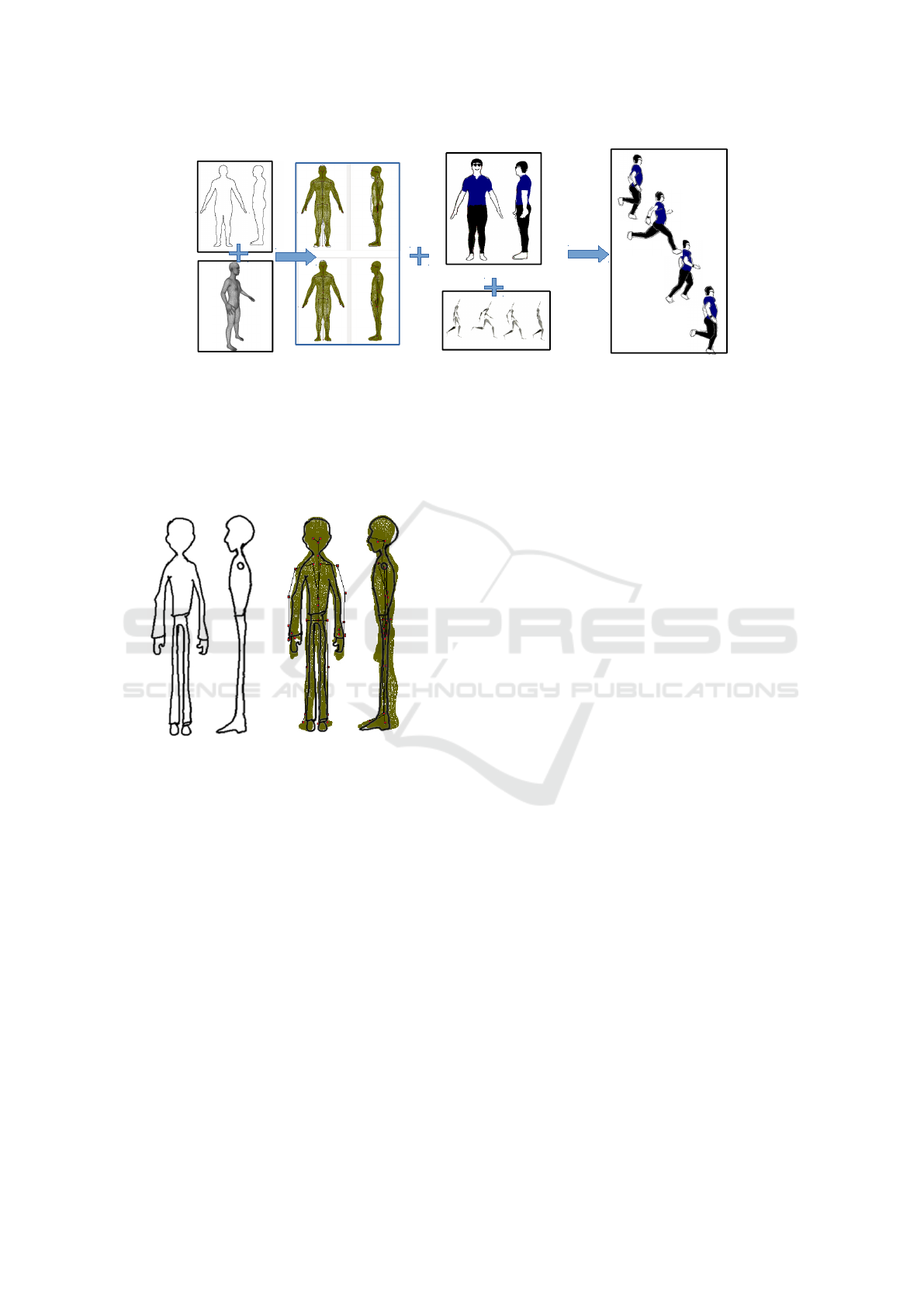
Figure 2: An overview of our system.
sketch. This has to be done only once and is a very
simple and intuitive process to follow.
The mesh can be posed as per the pose of the
skeleton by using a suitable form of skinning.
Figure 3: The character model sheet is given on the left.
The template mesh was registered to it by posing it and de-
forming its shape to fit the character and is drawn in brown
on the right.
4.2 Shape Fitting
Now we deform the mesh so that the silhouette of the
mesh matches the boundary shape of the character.
We first identify the boundary of the character sketch
by using contour tracing. This contour has to be a
closed contour, so it is closed as a post-processing
step if it is already not so. We then identify correspon-
dences with the silhouette vertices of the template
mesh. The correspondences are found by minimizing
a cost metric that depends on proximity of the contour
point to the mesh vertex, smoothness and continuity
of successive matching mesh vertices (Kraevoy et al.,
2009). We do this for both the front and side view
sketches of the character. Finally the corresponding
mesh vertices are deformed toward the contours of the
character by using mean value encoding (Kraevoy and
Sheffer, 2006). At the end of this process we have a
template mesh that approximately matches the char-
acter sketches in pose and shape.
An example of the template mesh registered to a
model sheet can be seen in Figure 3. The registration
is not perfect, as the mesh does not exactly match the
extreme shape of the character’s limbs in the model
sheet. However, this is not a problem for our method,
as the mesh is only used as a background proxy and
is never seen by the animator. This registration is suf-
ficient for us to proceed further and create the desired
animation of the character.
5 ANIMATION GENERATION
After the template mesh has been registered to the
sketch, we generate our animation. The motion is
added from any motion data supplied by the anima-
tor. This data can be obtained from pre-recorded
motion capture or keyframing. The rendering style
is based on the sketching style of the model sheets.
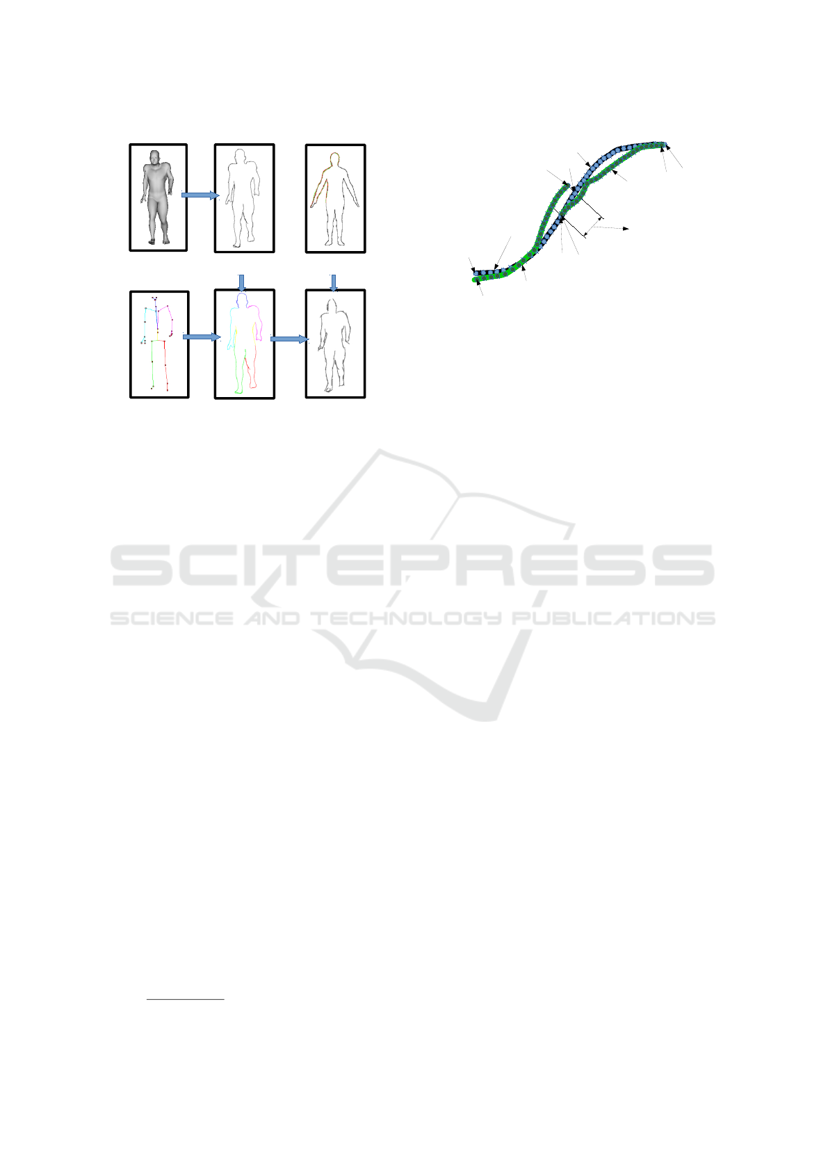
An overview of the animation generation process is
shown in Figure 4. The steps of the process are ex-
plained below.
5.1 Extracting Mesh Boundary Curves
The registered mesh is posed as per the skeleton pose
in the current frame of the given motion capture data,
using skinning. This mesh is then rendered into
the depth buffer, and silhouette edges are extracted.
These are then grouped as per the bones they are as-
sociated to and converted to B
´
ezier curves. We call
these curves boundary curves.
GRAPP 2018 - International Conference on Computer Graphics Theory and Applications
20
Registered
Mesh
Mesh
silhouette
Model sheet
with sketch strokes
Registered
Mesh
Skeleton
Boundary curves
assigned to bone
groups
Rendered using
strokes from the
model sheet
Figure 4: Generating the animation frame in the sketch style
of the model sheet.
5.2 Synthesis with Given Stroke Style
The character in the model sheet is converted to a
closed contour curve to aid mesh-sketch registration.
The animator can now sketch over the model sheet
in any desired stroke style. As the animator sketches,
the strokes drawn over the contour curve on the char-
acter on the model sheet, get associated with parts
of the contour curve. Each part of the contour that
matches a sketch stroke is called a segment. These
sketch strokes will, subsequently, be used to render
the animation. For each stroke, S
i
, the following at-
tributes are stored
1. Samples points that make up the stroke, s
i, j
.
2. Segment of the contour curve on the model sheet
to which stroke corresponds, C
i
.
3. Index of the sample on C
i
to which each stroke
sample s
i, j
corresponds, n
i, j
. The point on the
contour curve segment at n
i, j
, is given by c
i, j
.
4. Overlap with the previously drawn stroke if there
is any, O
i
Points on the contour curve, c
i, j
, that are clos-
est to the stroke sample points, s
i, j
are computed.
C
i
is then the curve segment between the minimum
and maximum c
i, j
’s. These attributes have been il-
lustrated in Figure 5. We also compute a average
overlap over all strokes, O
avg
. If the current stroke
is within a specified range of the previously drawn
stroke, we update the value for average overlap as,
O
avg
=
((n−1)∗O
avg
+O
i
)
n
, where n − 1 is number of pre-
Stroke
Stroke
Contour Curve
Segment
S
1
S
2
c
1,1
c
1,25
c
2,1
c
2,32
C
1
Contour Curve
Segment
C
2
Overlap
s
2,32
s
1,25
s
2,1
s
1,1
Figure 5: Parameters stored for strokes, shown in green.
The contour curve is shown in black. Here curve segment
C
1
has 25 sample points, and C
2
has 32 sample points shown
in blue. The sample points on the strokes are shown in dark
green.
viously accounted overlaps, and O
i
is the overlap for
the current stroke.
In order to synthesize the mesh boundary curves
in the style of the sketched strokes, the boundary
curves are sampled uniformly. The contour curve seg-
ments on the model sheet are also sampled at the same
rate. Now, we use a dynamic programming algorithm
to find the best matching contour segments for the
boundary curve, and then render the boundary curves
with a set of user strokes corresponding to that con-
tour segment. This process in illustrated in Figure 6
and is explained below.
Consider a part of a boundary curve with samples
numbered from a to b, is given by B
a:b
. Now for a
contour curve segment, C
i
, we compute an error met-
ric that measures similarity between them as
d
ab
i j
= argmin
R
i j
,T
i j
dist(R
i j
C
i, j :( j+b−a)
+ T
i j
, B
a:b
) (3)
Here j is the index for the sample point on the
contour segment C
i
, and we match contour segments
with b− a sample points, with B
a:b
, starting at each j.
This is represented as C
i, j :( j+b−a)
. R
i j
and T
i j
are rota-
tion and translation matrices. dist(..) returns the sum
of squared distances between the corresponding sam-
ples of B
a:b
and C
i
. Note that part of a boundary curve
may match only a part of the contour segment. Cor-
respondence is established by simple ordering of the
sample points, i.e., if the j-th sample on the contour
curve corresponds to the a-th sample on the bound-
ary curve, then the j + k-th sample will correspond to
the a + k -th sample. Iterating over all C
i
’s, the best
matching part of a contour curve segment is found as
i
∗
, j
∗
= argmin
i, j
d
ab
i j
.
Let d
ab
1
= d
ab
i
∗
j
∗
represent the value of the error
metric achieved at the best match. This error may be
reduced further if B
a:b
is replaced by smaller parts of
the contour segments (or consequently, more number
SheetAnim - From Model Sheets to 2D Hand-drawn Character Animation
21
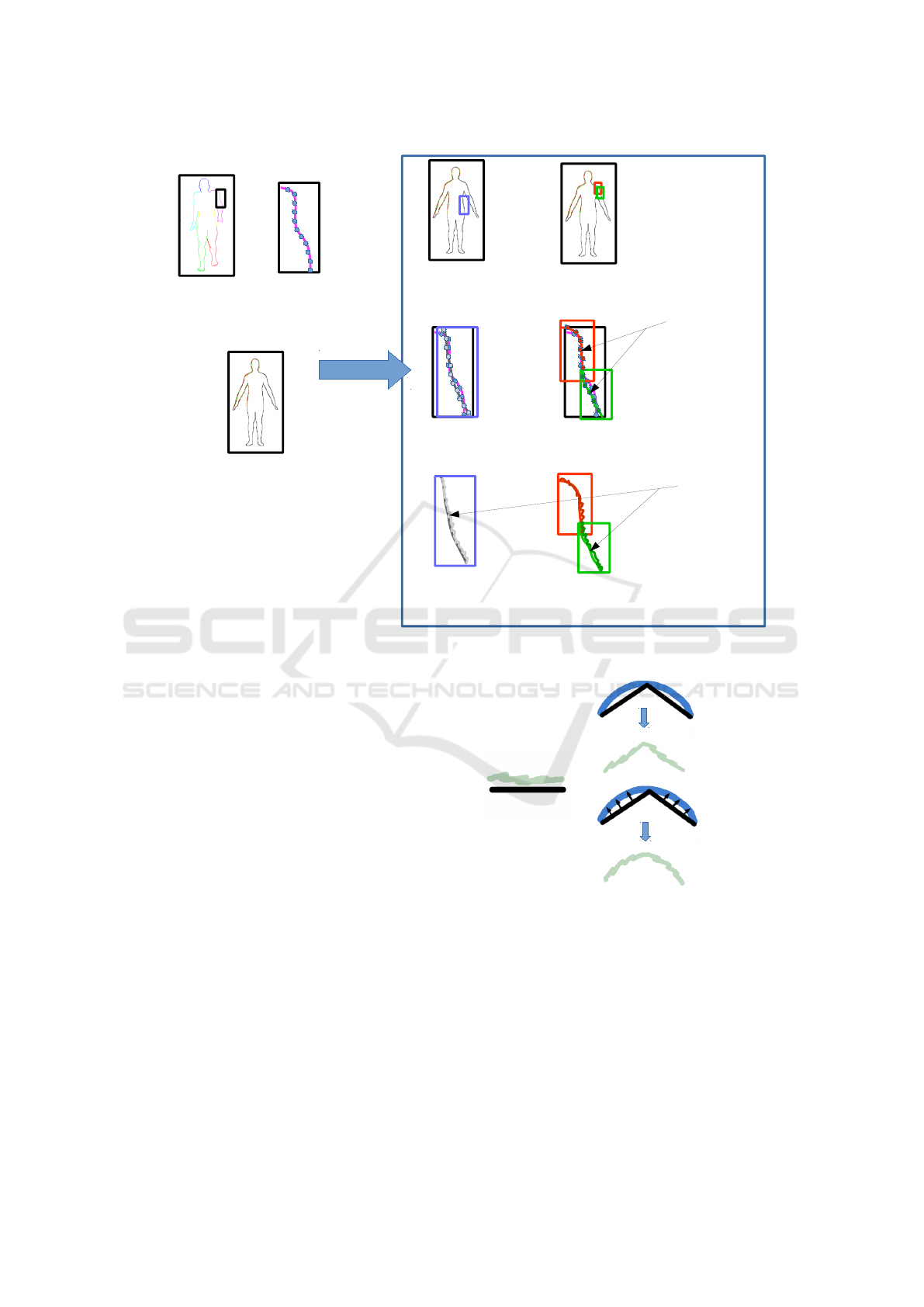
Contour curve segment(s) on the model sheet that
best match the boundary curve from the frame
is(are) searched using dynamic programming.
Boundary curves on the
animation frame are sampled.
The model sheet is converted to
a closed contour curve.
The animator sketches in their
stroke style over the model sheet.
Sketch strokes corresponding to
every contour curve segment are
recorded.
The best match may be with a single contour
segment or with two smaller consecutive
contour curve segments.
Match is
computed by
minimizing the
sum of squared
distances between
boundary and
contour curve
samples.
The sketch strokes correrponding to the contour
curve will get rendered for the boundary curve
from the frame.
Sketch strokes
1.
2.
3.
a.
b.
c.
or
or
or
Figure 6: Rendering boundary curves from an animation frame as sketch strokes.
of overlapping strokes). This is taken care of by also
looking at smaller sized solutions of the above match-
ing problem as
k
∗
= argmin
k
(d
ak
+ d
(k−O
avg
)b
), where a < k < b (4)
d
ab
2
= d
ak
∗
+ d
(k
∗
−O
avg
)b
+ b
p
(5)
where b
p
is a break penalty. This prevents unnec-
essary splitting of user strokes. The absolute mini-
mum value of the error metric is therefore, given by
d
ab
= min(d
ab
1
, d
ab
2
).
In order to find the actual stroke for replacing B
a:b
,
we will first rotate and translate contour curve C
i
∗
and
corresponding user stroke S
i
∗
as:
C
ab
= R
i
∗
j
∗
C
i
∗
, j
∗
:( j
∗
+b−a)
+ T
i
∗
j
∗
(6)
S
ab
= {R
i
∗
j
∗
s
i
∗
,k
+ T
i
∗
j
∗
|
s
i
∗
,k
∈ S
i
∗
∧ j
∗
≤ n
i
∗
,k
< j
∗
+ b − a} (7)
If B
a:b
is replaced directly by S
ab
, then we may
end up with poor results as shown in Figure 7. This is
because if B matches multiple contour segments, then
direct replacement does not guarantee smooth transi-
tion between 2 continuous strokes. In order to achieve
S
S
15
C
59
C
15
S
59
C
Directly replacing boundary
with corresponding strokes,
without smoothness
correction.
Replacing boundary with
corresponding strokes,
with smoothness
correction.
B
C
59
C
15
B
Figure 7: The effect, of pushing the contour curve toward
the boundary curve, on stroke smoothness is shown. S is the
stroke, C is the contour curve segment, and B is the bound-
ary curve.
smooth results, we push C
ab
towards B
a:b
as
˜
C
ab
= w
c
C
ab
+ w
b
B
a:b
˜s
ab
i
∗
,k
= s
ab
i
∗
,k
+ (˜c
ab
i
∗
,k
− c
ab
i
∗
,k
)
(8)
w
c
and w
b
are relative weights assigned to C
ab
and
B
a:b
, and they add up to 1. c
ab
m
j
represents the sam-
GRAPP 2018 - International Conference on Computer Graphics Theory and Applications
22
ple points on C
ab
at index m
j
. Similarly ˜c represents
the sample points on
˜
C. The smoothed stroke
˜
S
ab
,
is made up of the samples ˜s
ab
i
∗
,k
, where s
i
∗
,k
∈ S
i
∗
and
j
∗
≤ n
i
∗
,k
< j
∗
+b−a. This smoothing is optional and
can be disabled by the animator if not desired. Now,
B
a:b
can be replaced by a list of sketch strokes P
ab
,
where
P
ab
=
(
˜
S
ab
if d
ab
1
≤ d
ab
2
P
ak
∗
∪ P
(k
∗
−O
avg
)b
(9)
The above equations are computed recursively us-
ing dynamic programming. The output is a set of
sketch strokes, that correspond to the entire mesh sil-
houette. Examples of the same animation frames ren-
dered using different stroke styles is given in Figure 8.
Figure 8: The same animation frame generated with differ-
ent stroke styles varying from smooth long strokes to short,
overlapping strokes, left to right.
5.3 Adding Colour and Other Details
The animator can colour the model sheet. Since the
back of the character is not visible on the model sheet,
we assume that the colour painted on the front of the
character is the same as the colour on the back, for
a given part of the body. Mesh-sketch registration
allows us to register vertices of the mesh to parts of
the sketch. The colours from the sketch are projected
from the model sheet to the registered mesh vertices
in the background and reproduced in the drawing by
interpolation from the corresponding mesh vertices,
followed by a smoothing pass.
In addition to colour, the animator can also add de-
tails such as glasses, or short hair, or pockets on shirts,
to the character. The detail can be added to the model
sheet, or any in-between frame of the animation by
directly drawing on the generated frame.
In order to to this, the pixels making up the detail
are uniformly sampled. For each sample pixel i on a
frame j, p
i j
, we find the nearest mesh vertex, v
k
, on
the registered mesh. At each animation frame j, we
compute the set of motion vectors, D
j
= { f
j
k
|1 ≤ k ≤
N}, for all N mesh vertices. This gives us the amount
by which a mesh vertex moves in any given frame
of the animation. If the closest vertex, v
k
moves by
f
j
k
in frame j, we displace p
i j
by the same amount.
If the vertex gets hidden, we do not draw the pixel
sample as well. This enables us to handle occlusion
in the presence of moving body parts, and changing
viewpoints.
An example of a colour and details added to the
character and reproduced correctly during animation
can be seen in Figures 1, 11 and 12.
6 ENHANCING THE ANIMATION
The method described in the previous section pro-
duces frames for the animation in the animator’s
sketching style, with colour and other added details.
However, since this process is repeated independently
for each frame, there is no temporal coherence be-
tween the generated strokes. This produces a distract-
ing flickering in final output. If the animator wishes
to remove this, we allow the animator to apply a kind
of temporal smoothing that is explained below. Also,
we allow the animator to edit the skeleton in the mesh
at any frame of the animation. We explain below why
this is useful to the animator.
6.1 Temporal Smoothing
Figure 9: The first two images show consecutive frames
generated without temporal smoothing. The next two im-
ages show the same consecutive frames generated with tem-
poral smoothing.
In order to achieve temporal coherence between
strokes in consecutive frames, we track the joint an-
gles of the skeleton. As can be seen in Figure 4, we
group the boundary curves by the skeleton bones that
they are associated to. Therefore, we know which
boundary curves get effected if a bone moves. Now if
the boundary curves associated to a bone are synthe-
sized using sketch strokes in a frame, j. At frame
j + 1, if the joint angle change in the same bone
is more than 5 degrees then we recreate the sketch
SheetAnim - From Model Sheets to 2D Hand-drawn Character Animation
23
strokes from the boundary curves as explained in Sec-
tion 5. If not, then the sketch strokes from frame j
are repeated for frame j + 1, with appropriate rigid
transformations. Similarly, if the change in joint angle
from frame j + 1 to j + 2 is less than 5 degrees, again
the same strokes from frame j are repeated. The effect
of this is a temporal smoothing that reduces flicker-
ing in the final output substantially. This threshold of
5 degrees is determined empirically, as larger thresh-
olds resulted in strokes that did not match the frame
boundary curves well and smaller thresholds resulted
in flickering. Intuitively, the threshold is dependent
on the speed of motion being animated. An example
of this can be seen in Figure 9.
6.2 Skeleton Editing
We allow the animator to update the skeleton, by mov-
ing positions of joints manually, at any frame of the
animation. This will cause one or more bones of
the skeleton to rotate from their previous configura-
tions to newer orientations. The change acts as a hard
constraint and automatically updates all subsequent
frames in the generated animation accordingly, as the
mesh now uses the updated skeleton for generating
the animation. It is done by factoring in the rotation
caused by the change in configuration for each bone
into the skinning matrix for the bone. This causes the
mesh to deform differently, which in turn generates
the updated sketched animation frame. An example
of this kind of correction can be seen in Figure 10.
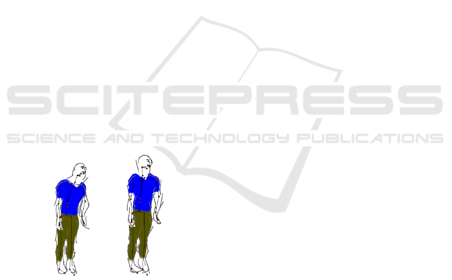
Figure 10: The left frame is generated by the original skele-
ton. The right image shows the same frame after the skele-
ton has been updated by the animator. The character ap-
pears more upright, after the correction is made.
7 RESULTS
We have tested our system with different charac-
ter model sheets and different motions and produced
multiple different animations. These can be seen in
Figures 11 and 12. In the result shown in Figure 12,
we see that our method works correctly even for if
we only fill colour details in one view on the model
sheet. Our system correctly predicts the colour in the
relevant parts of the character during animation. We
have used the same template mesh model for all an-
imations. The actual animations can be seen in the
supplementary video submitted with this paper.
8 LIMITATIONS
While our method works for a large class of character
model sheets, and allows the animator a lot of flexibil-
ity in creating the animation, it has certain limitations.
We cannot handle free flowing clothes or hair on the
model sheets. One way to do that is to adopt a method
like the one presented by Jain et al. (Jain et al., 2012).
Another limitation is that though we can handle
sketch strokes of different kinds, we cannot handle
complex composite sketch strokes with a lot of over-
lap, like cross-hatching. We also cannot vary the kind
of brush or pen being used to add drawing detail. This
would require us to implement a complete brush and
paint subsystem.
9 CONCLUSIONS
We have presented a method to generate 2D hand
drawn character animation from a model sheet of a
character. The animator can use any stroke style to
sketch on the model sheet, add colour and details.
These get automatically reproduced on the resulting
animation. We smooth the output to make it tempo-
rally coherent. A mesh is registered to the character
on the model sheet to enable all this. The animator
also has the option to edit and correct any part of the
animation by changing the skeleton used to deform
the mesh, and the strokes produced by our method.
Our system has been used by a few novice animators,
and they have found the system easy and intuitive to
use.
As future extensions to our system, we would like
to extend it so that the animator can generate novel
animation sequences and not be restricted by input
motion data. This could be done using various kinds
of motion synthesis techniques, that make the process
even more intuitive and simple for the animator.
REFERENCES
Bassett, K., Baran, I., Schmid, J., Gross, M., and Sumner,
R. W. (2013). Authoring and animating painterly char-
GRAPP 2018 - International Conference on Computer Graphics Theory and Applications
24

acters. ACM Trans. on Graph., 32(5):156:1–156:12.
Ben-Zvi, N., Bento, J., Mahler, M., Hodgins, J., and Shamir,
A. (2016). Line-drawing video stylization. Comp.
Graph. Forum, 35(6):18–32.
Bessmeltsev, M., Chang, W., Vining, N., Sheffer, A.,
and Singh, K. (2015). Modeling character canvases
from cartoon drawings. ACM Trans. on Graph.,
34(5):162:1–162:16.
Davis, J., Agrawala, M., Chuang, E., Popovi
´
c, Z., and
Salesin, D. (2003). A sketching interface for articu-
lated figure animation. In Proceedings of the ACM
SIGGRAPH/Eurographics Symposium on Computer
Animation, pages 320–328.
Grasp, C. T. and Taylor, C. J. (2000). Reconstruction of ar-
ticulated objects from point correspondences in a sin-
gle uncalibrated image. Computer Vision and Image
Understanding, 80:677–684.
Henrikson, R., De Araujo, B., Chevalier, F., Singh, K.,
and Balakrishnan, R. (2016). Storeoboard: Sketching
stereoscopic storyboards. In Proceedings of the CHI
Conference on Human Factors in Computing Systems,
CHI ’16, pages 4587–4598.
Hertzmann, A., Oliver, N., Curless, B., and Seitz, S. M.
(2002). Curve analogies. In Proceedings of the 13th
Eurographics Workshop on Rendering, EGRW ’02,
pages 233–246.
Igarashi, T., Matsuoka, S., and Tanaka, H. (1999). Teddy:
A sketching interface for 3d freeform design. In Pro-
ceedings of the 26th Annual Conference on Computer
Graphics and Interactive Techniques, pages 409–416.
Jain, E., Sheikh, Y., and Hodgins, J. (2009). Leveraging the
talent of hand animators to create three-dimensional
animation. In Proceedings of the 2009 ACM SIG-
GRAPH/Eurographics Symposium on Computer An-
imation, pages 93–102.
Jain, E., Sheikh, Y., Mahler, M., and Hodgins, J. (2012).
Three-dimensional proxies for hand-drawn characters.
ACM Trans. on Graph., 31(1):8:1–8:16.
Jones, B., Popovic, J., McCann, J., Li, W., and Bargteil, A.
(2015). Dynamic sprites: artistic authoring of inter-
active animations. Computer Animation and Virtual
Worlds, 26(2):97–108.
Kalnins, R. D., Davidson, P. L., Markosian, L., and Finkel-
stein, A. (2003). Coherent stylized silhouettes. ACM
Trans. on Graph., 22(3):856–861.
Kalnins, R. D., Markosian, L., Meier, B. J., Kowalski,
M. A., Lee, J. C., Davidson, P. L., Webb, M., Hughes,
J. F., and Finkelstein, A. (2002). Wysiwyg npr: Draw-
ing strokes directly on 3d models. ACM Trans. on
Graph., 21(3):755–762.
Kraevoy, V. and Sheffer, A. (2006). Mean-value geometry
encoding. In International Journal of Shape Model-
ing, pages 29–46.
Kraevoy, V., Sheffer, A., and van de Panne, M. (2009).
Modeling from contour drawings. In Proceedings of
the 6th Eurographics Symposium on Sketch-Based In-
terfaces and Modeling, pages 37–44.
Levi, Z. and Gotsman, C. (2013). ArtiSketch: A system for
articulated sketch modeling. Comp. Graph. Forum,
32(2):235–244.
Magnenat, S., Ngo, D. T., Zund, F., Ryffel, M., Noris,
G., Rothlin, G., Marra, A., Nitti, M., Fua, P., Gross,
M., and Sumner, R. W. (2015). Live texturing of
augmented reality characters from colored drawings.
IEEE Trans. on Vis. and Comp. Graph., 21(11):1201–
1210.
MakeHuman (2016). http://www.makehuman.org/.
Patel, P., Gupta, H., and Chaudhuri, P. (2016). Tracemove:
A data-assisted interface for sketching 2d character
animation. In Proceedings of GRAPP, pages 191–199.
Thorne, M., Burke, D., and van de Panne, M. (2004). Mo-
tion doodles: An interface for sketching character mo-
tion. In ACM SIGGRAPH 2004 Papers, pages 424–
431.
Whited, B., Daniels, E., Kaschalk, M., Osborne, P., and
Odermatt, K. (2012). Computer-assisted animation of
line and paint in Disney’s Paperman. In ACM SIG-
GRAPH 2012 Talks, pages 19:1–19:1.
Xing, J., Wei, L.-Y., Shiratori, T., and Yatani, K. (2015).
Autocomplete hand-drawn animations. ACM Trans.
on Graph., 34(6):169:1–169:11.
Zhou, S., Fu, H., Liu, L., Cohen-Or, D., and Han, X. (2010).
Parametric reshaping of human bodies in images. In
ACM SIGGRAPH 2010 Papers, pages 126:1–126:10.
SheetAnim - From Model Sheets to 2D Hand-drawn Character Animation
25
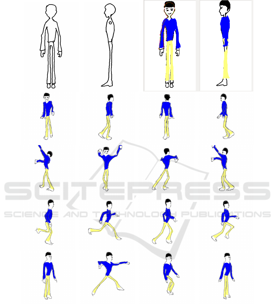
Figure 11: The top row shows the input model sheet on the left, and the model sheet with details added by the animator on
the right. Frames from a walk, dance, run and jump animation are shown in the rows below.
GRAPP 2018 - International Conference on Computer Graphics Theory and Applications
26
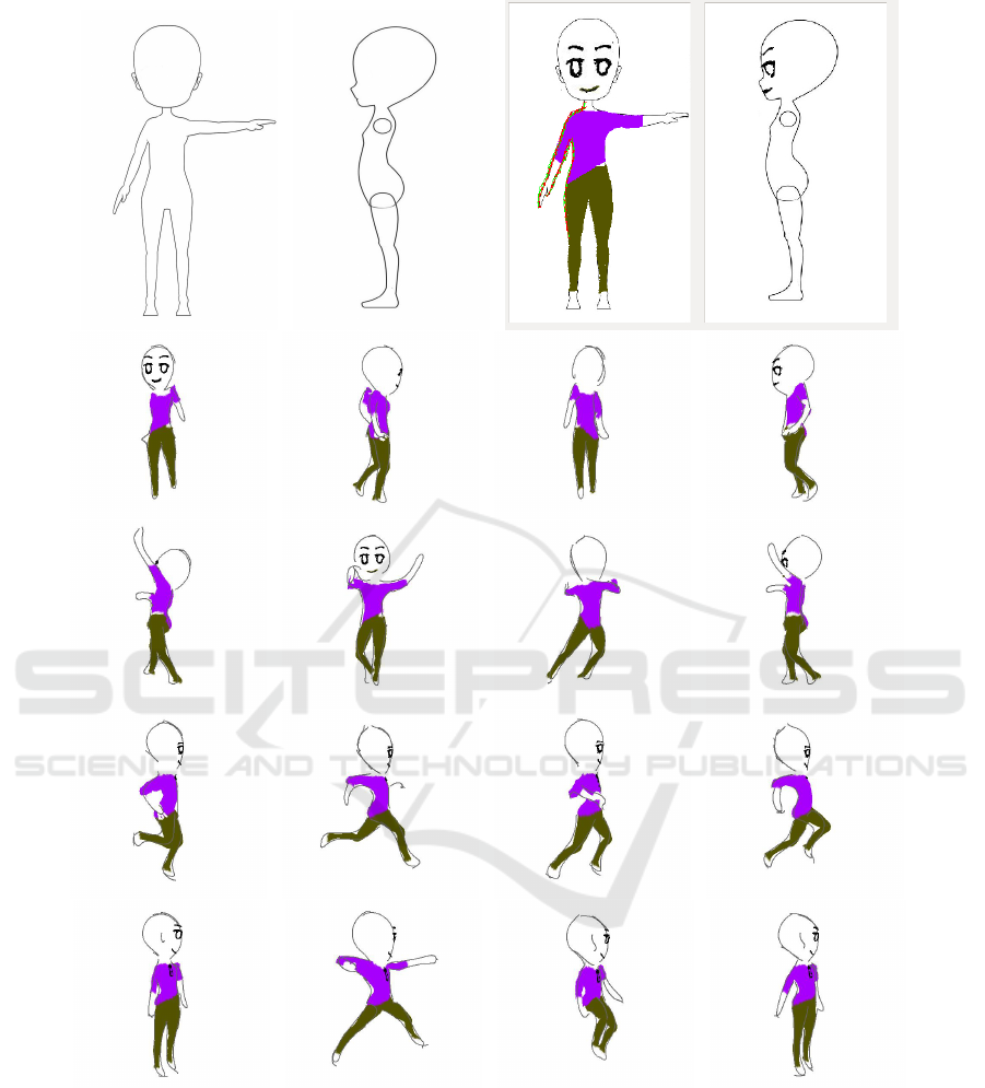
Figure 12: The top row shows the input model sheet on the left, and the model sheet with details added by the animator on
the right. Frames from a walk, dance, run and jump animation are shown in the rows below.
SheetAnim - From Model Sheets to 2D Hand-drawn Character Animation
27
