
A Global Path Planning Strategy for a UGV from Aerial Elevation
Maps for Disaster Response
D. C. Guastella, L. Cantelli, C. D. Melita and G. Muscato
Dipartimento di Ingegneria Elettrica Elettronica e Informatica, Università degli Studi di Catania, Catania, Italy
Keywords: Outdoor Environments, Rough Terrain, Unmanned Aerial Vehicle, Tracked Vehicle, Traversability, Path
Planning.
Abstract: An approach for global path planning of an Unmanned Ground Vehicle (UGV) is proposed, including basic
traversability analysis of the rough terrain to get through. The navigation capabilities of the UGV, in
performing such analysis, are considered. The here proposed solution is organized into two following
phases: first an aerial scan of the environment is executed by a UAV (Unmanned Aerial Vehicle) and the
elevation map of the area is built; after that, a set of processing algorithms is applied to such surface model
to derive a 2D costmap (whose costs are based on the prior traversability analysis) which is given as input of
a D* path planner. The resulting path can be eventually delivered as a sequence of waypoints for a
navigation controller on the field mobile platform.
1 INTRODUCTION
The need to have an autonomous robot moving
across outdoor unstructured environments is not
fully fulfilled by current state of the art in robotics,
although it does represent a crucial point especially
for disaster-response robots. Cooperative systems,
namely unmanned aerial and ground vehicles wor-
king together, appear to show good performances for
the above mentioned applications, thus justifying the
increased interest on such approach in robotics
research. A recent result is reported by Siegwart et
al., (2015), where mechanical and structural aspects
of a legged robot and a fixed-wing unmanned aerial
vehicle are enhanced in order to improve their
autonomy and stability in those harsh environments
resulting from natural disasters. In some cases, the
development of cooperative multi-robot systems has
been encouraged by international robotics
competitions, like EuRathlon (Schneider,
Wildermuth and Wolf, 2015) or RoboCup Rescue
(Kitano and Tadokoro, 2001), as in the case
represented by ICARUS team, described by
Marques et al. (2016), which was able to create
cooperating robotic platforms in ground, air, and
even maritime domains. It is apparent that there is
the need to combine the contributions of
heterogeneous platforms, especially when facing
search and rescue scenarios. In addition, the
difficulty of dealing with such risky environments is
the severely limited possibility to perform non-
destructive trials in the area of interest with the
robotic platforms, in particular for UAVs. To
address this issue some solutions have been
proposed (Astuti et al., 2008).
The aim of the present work is to set up a
procedure for the global path planning of an
unmanned ground vehicle within an outdoor
unstructured environment, taking into account the
specific motion capabilities of the considered
vehicle. The planning procedure is described as
follows: starting from a Digital Elevation Model
(DEM), which is built from the aerial photographic
scan of the environment done by a multi-rotor, a
traversability analysis on such terrain surface is
performed, and finally an optimal path is computed,
in terms of reducing the traversing cost. The path is
planned with the D* algorithm (Stentz, 1994). The
latter was preferred over other planning methods
since it gives the possibility to include costs into the
map and, moreover, it is optimized in replanning
whenever such map of costs, i.e. the costmap,
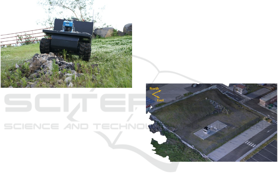
changes. The robotic platform considered in this
work is the U-Go Robot, a tracked vehicle designed
for rough terrain navigation (Bonaccorso et al.,
2012), shown in Figure 1.
Guastella D., Cantelli L., Melita C. and Muscato G.
A Global Path Planning Strategy for a UGV from Aerial Elevation Maps for Disaster Response.
DOI: 10.5220/0006298303350342
In Proceedings of the 9th International Conference on Agents and Artificial Intelligence (ICAART 2017), pages 335-342
ISBN: 978-989-758-219-6
Copyright
c
2017 by SCITEPRESS – Science and Technology Publications, Lda. All rights reserved
335
The details about the digital elevation model
reconstruction are given in Section 2, while Section
3 describes the first basic processing on such model,
focusing on our case study. Then Section 4 reports
the generation of the costmap, taking into account
the traversability of the terrain with respect to our
robotic platform. This point is the core and
innovative part of the work. In Section 5 the results
provided by the D* planner are shown, confirming
the avoidance of those areas particularly hostile to
be traversed. The final section includes a summary
and an outlook for the current project.
Figure 1: The U-Go Robot.
2 DEM RECONSTRUCTION
The starting data of the whole procedure is the DEM
of the outdoor environment under inspection. This
kind of model is typically referred to as 2.5D
representation of the real world. The terrain surface
to be represented is divided into cells and for each
cell the highest altitude is stored, thus obtaining a
matrix of altitudes. The result is a top view of the
environment; therefore, the main drawback of the
elevation maps consists of the impossibility to
include overhanging structures or multiple height
levels for one cell. However, they are still a good
trade-off between computing power and
representation accuracy in modeling outdoor areas.
Each value inside the elevation matrix is pointed out
with a couple of integers indicating its row and
column. However, these heights have a relative
distance in the real world, given by the resolution of
the DEM, i.e. the size of the cells the terrain was
divided into.
An innovative aspect lies in the DEM
reconstruction. In particular, a scanning mission is
previously performed by a quad-copter, during
which the UAV autonomously covers the whole area
to be reconstructed and takes regularly spaced
pictures by means of a stabilized on-board camera.
Then a commercial mapping software, Pix4Dmapper
Pro, processes all the acquired pictures to recreate
the 3D structure of the scanned terrain. Among
different kind of processing outputs, the mapping
software delivers the digital elevation model, along
with its georeferencing information.
The environment considered in this case study is
the external area of D.I.E.E.I. laboratories of the
University of Catania. The resulting DEM is given
in UTM coordinates (Universal Transverse of
Mercator) with ellipsoidal heights (WGS84).
Furthermore, we focused our attention on a
specific area within the outdoor environment, which
resembles a landslide scenario, including areas with
different slopes and level of navigation difficulties.
The 3D textured mesh of this area is reported in
Figure 2.
With an average flight altitude of 30 m and an
on-board camera of 12.4 megapixels, the
reconstructed digital elevation model has a
resolution lower than 1 cm/cell (0.986 cm/cell)
along both the North and East directions.
Figure 2: The 3D textured mesh of the landslide-like area
recreated by the mapping software.
3 DEM PRE-PROCESSING
The overall processing of the elevation map is
carried out in Matlab. Firstly the DEM, saved in
geotiff format, is loaded in Matlab including its
georeferencing information. At the same time the
DEM is downsampled, thus obtaining a final spatial
resolution of 9.86 cm/cell for the elevation map.
This downsampling is performed to reduce the
computing burden in the following processing steps
and also for geometric considerations related to the
robotic platform. In fact, the U-Go is a 75 cm long
and 88 cm large tracked vehicle, with 18 cm wide
rubber tracks. Therefore, working with height values
ICAART 2017 - 9th International Conference on Agents and Artificial Intelligence
336
spaced roughly every 10 cm is a sufficient
approximation of the terrain surface over which the
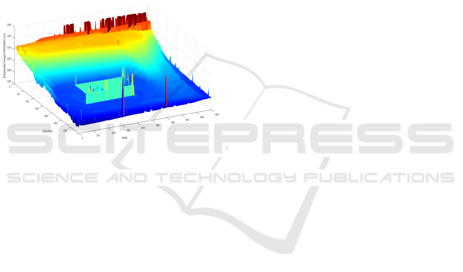
robot is supposed to move. Finally, from the whole
DEM the region of interest is cropped, i.e. the
landslide-like area. The final digital elevation model
under study is a 451×337 matrix, representing an
area of 44.47×33.23 m.
Since the idea was to generate a costmap
including both maximum non-traversable slopes and
height steps, a virtual wall was included into the
digital elevation model by adding a fixed value to a
rectangular shaped contour. Therefore, the final
matrix considered for the global path planning is a
slightly modified version of the original one, and in
Figure 3 the resulting surface is depicted.
Figure 3: The reconstructed surface of the region of
interest, after virtual wall insertion.
4 MAP GENERATION
Once defined the digital elevation model of the area
under investigation, the following steps consist of
processing such model in order to derive the
costmap required by the path-planning algorithm.
4.1 U-Go Traversability Capabilities
A proper path planning cannot be conceived without
taking into account the real motion actuation
performed by the specific robotic platform,
especially when the UGV is asked to autonomously
cover hostile terrains and so a terrain traversability
analysis must be included as well.
This task has been accomplished in literature in
different manners. A remarkable example in this
sense is shown by Santamaria-Navarro et al. (2015),
which consists of application of learning models for
traversable and non-traversable area classification.
In that work the ground truth was made up of terrain
appearance and geometry acquired by the vehicle
while being teleoperated in the environment. A very
similar method was also pursued by Silver, Bagnell,
and Stentz (2010), where a skid-steering platform
was firstly maneuvered by an expert, while learning
a mapping between sensor data and path planning
costs. Therefore, the vehicle usually learns in two
senses: inferring its motion dexterity and/or
determining the features of traversable and non-
traversable terrain patches.
In our work, the U-Go was initially teleoperated
over some testing areas, bringing its navigation
performances to the limit. During these first experi-
mental sessions a huge amount of proprioceptive
data have been acquired; among them, the robot
pose (roll, pitch and yaw angles of the vehicle) and
the GPS coordinates.
As a first approach, two simple measures, in
defining the U-Go motion capabilities, have been
considered. From the inspection of pitch excursion,
the minimum and maximum values recorded for this
angle were respectively -29° and 32°; however
nearly all the remaining values were within the [-
25°, 25°] interval, whose limits are around the 80%
of the two extreme values detected. Therefore, the
maximum traversable slope for preventing the
vehicle overturning is established at 25°, thus
including a safety margin angle. Finally, the
maximum height step that the U-Go is capable to
climb was observed to be 15 cm.
4.2 Binary Occupancy Grids
Generation
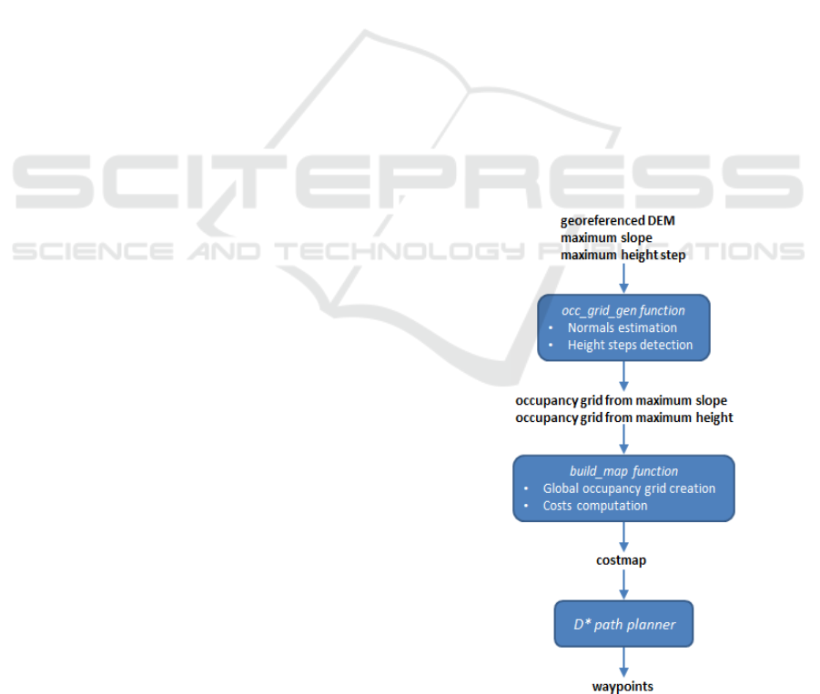
The georeferenced digital elevation model, descry-
bed in Section 3, is thus delivered to a Matlab
processing function, which requires only maximum
traversable slope and maximum climbable height, as
inputs, and provides two binary occupancy grids, as
outputs. The algorithm consists of the following
main steps:
Surface normals estimation in each point of
the map;
Height steps detection for each point of the
map;
Binary occupancy grids generation based on
maximum slope and maximum climbable
height.
Normals are used for the terrain slope
assessment. The choice of using normals is justified
by the possibility of quantitatively determining the
slope exhibited by the terrain patch surrounding a
given point. Using normals we essentially look at the
z-component of these vectors. In fact, this compo-
A Global Path Planning Strategy for a UGV from Aerial Elevation Maps for Disaster Response
337
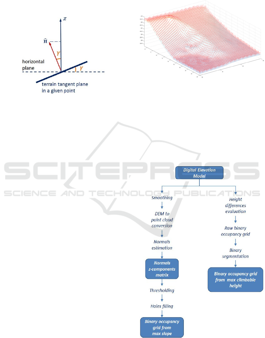
nent depends only on the cosine of the slope of the
plane tangent to the surface in the considered point,
with respect to the horizontal plane, as shown in
Figure 4.
Figure 4: Normal z-component and tangent plane slope.
Normals estimation is performed using the imple-
mentation employed by Taylor, Nieto and Johnson
(2015), which, however, is conceived to handle
point clouds, i.e. xyz coordinates in the space.
Therefore, in order to carry out this processing step,
the DEM has to be previously converted into a point
cloud.
The normals estimation algorithm computes a
covariance matrix of a user-defined number of
nearest neighbors of each query point and then
performs a principal component analysis (PCA). The
eigenvector associated to the minimum eigenvalue
gives the best normal direction estimate of the
tangent plane in the query point (Rusu, 2009).
Furthermore, this PCA-based technique requires the
indication of a point of view, to determine the
normal vectors orientations, consistently with the
surface. In our case a point of view in the center of
the surface, with a high altitude value, was chosen,
in order to have nearly all normals pointing in the
positive direction of the z-axis, thus allowing us to
deal with positive z-components.
Normals estimation has been carried out on a
smoothed version of the DEM, which has been
obtained by applying a Gaussian convolutional filter
over the matrix. The standard deviation of the
Gaussian filter establishes the kernel size of the
convolutional filter. In our case a standard deviation
equal to 2 is chosen, leading to a kernel size equal to
2∙
2
1=9. This particular value has been
chosen since it has shown to improve the quality of
the normal estimation results, generating a less noisy
output, without compromising too much the final
resolution, thinking of the robotic platform size.
Then the smoothed matrix has been converted into a
point cloud and normals for each point have been
computed. In Figure 5 a sample graphical result is
shown.
Figure 5: Detail of normals estimated over the terrain.
The z-components of these normals are
rearranged as a matrix, in order to have a one-to-one
matching with the original DEM. This matrix of z-
components is finally compared with a threshold,
which is the cosine of the slope above which the
terrain is non-traversable, i.e. 25° (see Figure 4). In
this manner the first binary occupancy grid is
generated. To exclude areas all surrounded by non-
traversable points (and then unreachable), holes in
the binary image are immediately filled.
Figure 6: Scheme of the processing phases of the two
occupancy grids generation.
ICAART 2017 - 9th International Conference on Agents and Artificial Intelligence
338
Then the Matlab processing function builds the
second binary occupancy grid, which looks for
discontinuities in the height values exceeding a
maximum threshold (namely steps or walls). The
method to realize this binary occupancy grid is
straightforward: for each element of the DEM we
compute all the absolute differences between the
element value and the values of its eight adjacent
surrounding elements; if at least one of these
differences is above the threshold, the cell is marked
as an obstacle. It is apparent that such solution does
not hold for the DEM boundaries; therefore, they are
discarded in the following steps. Finally, a binary
segmentation is performed on the occupancy grid:
this allows to exclude unreachable isolated areas (all
surrounded by non-traversable cells) and, more
importantly, to make the shapes of these real
obstacles stand out, rather than simply filling holes
as in the previous case. In Figure 6 a sketch of the
processing steps carried out within the Matlab
function is reported.
4.3 Costmap
The last map to create is the global costmap for the
D* path planner (Stentz, 1994), depending on which
the algorithm identifies the optimal path, i.e. the
route with lower cumulative cost. The costs within
this map are generically values greater than zero; in
the implementation that we use, included in the
robotics toolbox v. 9.10 (Corke, 2011), the algorithm
works in particular with costs greater than one. In
any case obstacles are mapped with infinite values.
A second Matlab function is in charge of
generating this costmap. Firstly a global binary
occupancy grid is built by simply merging the two
occupancy grids described in the previous section
(i.e. taking the union of their non-traversable cells).
Note that in this binary map obstacles and free cells
are respectively represented with one and zero, but
in the final costmap they will be respectively
remapped with infinity and one. Furthermore, the
costs of non-obstacle cells are derived as explained
below.
To prevent the path planner from choosing cells
too close to those marked as obstacles, the costs of
all these cells are increased by dilating obstacle
areas, applying a large-sized Gaussian kernel to the
binary occupancy grid and multiplying the resulting
matrix by a magnifying factor. In this way only costs
of the desired cells are increased, since the ones
farther from obstacles still have a zero value after
the dilation, which obviously is not affected by the
multiplication. A second contribution included in
non-obstacle cells costs is the slope. In fact,
although all cells with slope higher than 25° are
already marked as obstacles, it is still preferable to
avoid to have the robot traversing terrain patches
with high slope and, in general, to move along a path
with as lower steepness as possible, both for safety
and energy efficiency reasons. Therefore, starting
from the matrix of normals z-components (described
in the previous subsection), we associate higher
costs to those cells with inclination close to 25° (i.e.
whose values in the matrix is close to cos(25°)), and
costs close to 1 (i.e. traversable cells in the D*
costmap) to those cells with slope close to 0° (i.e.
whose value in the matrix is close to 1).
A further feature, which was considered in the
first instance of the costmap derivation, was the
terrain unevenness. In fact, PCA analysis performed
on the point cloud allows to acquire information on
both the terrain irregularity and the terrain normals
at the same time, since they are respectively related
to the smallest eigenvalue and the corresponding
eigenvector of the covariance matrix. However, this
kind of information was not included in the final
costmap since, in our case study, it appeared to
introduce only noise in the planned path, without
any remarkable quality increase, since highly
irregular areas have been already marked as
obstacles.
Figure 7: Scheme of the overall procedure, starting from
the digital elevation model up to waypoints generation.
A Global Path Planning Strategy for a UGV from Aerial Elevation Maps for Disaster Response
339
Eventually, to obtain the global costmap for the
D* algorithm, all matrices are merged together: the
global occupancy grid, including cells with infinite
costs (i.e. obstacles), with the two matrices of costs
for obstacle-closeness and costs for cells slopes.
Once provided the costmap, the path planner can
compute the optimal route, which is converted into a
sequence of waypoints. In Figure 7 a summarizing
scheme of the overall workflow is shown.
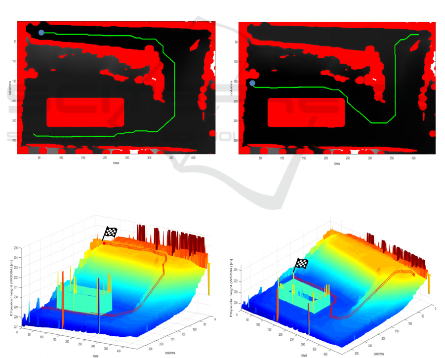
5 RESULTS AND SIMULATIONS
Two sample paths have been computed, from two
different couples of starting and final points,
delivering them to the D* planner. In Figure 8 these
paths are shown: both the starting points, and the
final points (indicated with blue dots) are chosen to
make the vehicle reaching the upper part of the area
starting from the lower part and vice-versa. The
lighter grey shades are those cells of the costmap
with higher cost, while red areas are absolutely non-
traversable zones (i.e. those marked as obstacles in
the global binary occupancy grid described in the
previous subsection).
Then these trajectories are converted into UTM
and longitude/latitude coordinates, in order to be
provided as references to the waypoint navigation
controller on board of the tracked vehicle. A Matlab
script running on a laptop, acting as a control base
station, is employed to interact with the vehicle by
means of the ROS (Robot Operating System)
communication middleware, thanks to the Robotics
System Toolbox, which provides an interface
between Matlab and the ROS network.
In Figure 9 the red tracks represent the 3D
reconstructions of the paths over the terrain surface.
a) b)
Figure 8: Examples of computed paths: a) path #1 (path length: 75.62 m); b) path #2 (path length: 56.20 m).
a) b)
Figure 9: Track of the vehicle over the terrain: a) path #1; b) path #2.
ICAART 2017 - 9th International Conference on Agents and Artificial Intelligence
340

6 CONCLUSIONS AND FUTURE
DEVELOPMENTS
The work presented in this paper is an end-to-end
procedure to perform a global path planning for a
UGV, starting from a digital elevation model built
from an aerial photographic acquisition, carried out
by a UAV, of the field over which the ground
vehicle has to move. This approach is particularly
relevant for search and rescue scenarios, where the
environment to cope with is strongly unstructured,
heterogeneous and not known a priori.
Thanks to the simple kind of analysis performed
on the surface model, the procedure allows to obtain
a traversable path in a very brief time interval,
avoiding dangerous steep slopes and steps. In this
manner, the vehicle is capable to start operating over
the area to be rescued, while more task-specific
missions can be planned in a longer time. Moreover,
the solution here presented can constitute a good
background to be integrated with a local obstacle
avoidance controller, supported by the optimized
replanning method of the D* algorithm.
A future development could be to move to a full
3D representation of the outdoor environment, for
instance by using octomaps (Hornung et al., 2013),
or dense point clouds. In this manner overhanging
structures, which are quite often present in disaster
areas, and terrain roughness analysis could be
included, thus allowing to find more traversable
paths. Moreover, some solutions to obtain the
environment reconstruction in real-time could be
introduced such as the one reported in Pizzoli,
Forster and Scaramuzza (2014).
However, the work here reported, even if much
simpler, could be smartly integrated into a more
complex solution to reduce computing burden, for
instance, focusing only on those traversable terrain
areas identified by the costmap generation process.
Another point to be enhanced is the overall
system robustness. The communication system
should not only rely on the ROS framework, which
is more suitable for reliable communication network.
The capability of moving also in GPS-denied
environments should be included, by resorting to
SLAM or Visual Odometry, as done by Siegwart et
al. (2015) and Weiss, Scaramuzza and Siegwart
(2011), thus avoiding to trust only on GPS
information, not always available in disaster areas.
Matlab and ROS have been used in this prototyping
phase to study the first results of the procedure;
however, everything should be embedded in a
companion PC on-board to the vehicle, thus making
the whole planning strategy much less “manual”,
once platform-dependent parameters have been
properly tuned.
Finally, while computing the path, the orientation
of the platform with respect to the terrain was not
considered. This would result in too much of a
conservative representation of the area, in terms of
traversability, because for each terrain cell only
maximum slope is considered. Therefore a first
integration will be to use a modified version of the
D* planner and to consider also the physical size of
the platform and not just schematize it as a point
mass.
ACKNOWLEDGEMENTS
This work was carried-out in the framework of the
CLARA PON project. The Project CLARA (CLoud
plAtform and smart underground imaging for natural
Risk Assessment) is funded by MIUR under the
program PON R&C SCN_00451.
REFERENCES
Siegwart, R., Hutter, M., Oettershagen, P., Burri, M.,
Gilitschenski, I., Galceran, E., Nieto, J., 2015. Legged
and flying robots for disaster response. In World
Engineering Conference and Convention 2015
(WECC2015).
Schneider, F.E., Wildermuth, D., Wolf, H. L., 2015.
ELROB and EURATHLON: improving search &
rescue robotics through real-world robot competitions.
In IEEE 10th International Workshop on Robot
Motion and Control (RoMoCo).
Kitano, H., Tadokoro, S., 2001. Robocup rescue: a grand
challenge for multiagent and intelligent systems. In AI
magazine, vol. 22(1).
Marques, M. M., Parreira, R., Lobo, V. et al., 2016. Use of
multi-domain robots in search and rescue operations -
contributions of the ICARUS team to the euRathlon
2015 challenge. In Oceans 2016.
Astuti, G., Longo, D., Melita, C. D., Muscato, G., Orlando
A., 2008. HIL tuning of UAV for exploration of risky
environments. In International Journal on Advanced
Robotic Systems, Vol. 5(4).
Stentz, A., 1994. The D* algorithm for real-time planning
of optimal traverses. Tech. Rep. CMU-RI-TR-94-37,
The Robotics Institute, Carnegie-Mellon University.
Bonaccorso, F., Longo, D., Muscato, G., 2012. The U-Go
Robot, a multifunction rough terrain outdoor tracked
vehicle. In Proceedings of the 2012 World Automation
Congress WAC2012.
Santamaria-Navarro, A., Teniente, E. H., Morta, M.,
Andrade-Cetto, J., 2015. Terrain classification in
complex three-dimensional outdoor environments. In
Journal of Field Robotics, vol. 32(1), pp. 42-60.
A Global Path Planning Strategy for a UGV from Aerial Elevation Maps for Disaster Response
341

Silver, D., Bagnell, J. A., Stentz, A., 2010. Learning from
demonstration for autonomous navigation in complex
unstructured terrain. In The International Journal of
Robotics Research vol. 29(12), pp.1565-1592.
Taylor, Z., Nieto, J., Johnson, D., 2015. Multimodal
sensor calibration using a gradient orientation
measure. In Journal of Field Robotics, vol. 32(5), pp.
675-695.
Rusu, R. B., 2009. Semantic 3D object maps for everyday
manipulation in human living environments. PhD
thesis, Computer Science department, Technische
Universität Müchen, Germany.
Corke, P. I., 2011. Robotics, Vision & Control, Springer.
Hornung, A., Wurm, K. M., Bennewitz, M., Stachniss, C.,
Burgard, W., 2013. OctoMap: an efficient probabilistic
3D mapping framework based on octrees. In
Autonomous Robots, vol. 34(3), pp. 189-206.
Pizzoli, M., Forster, C., Scaramuzza, D., 2014. REMODE:
probabilistic, monocular dense reconstruction in real
time. In IEEE International Conference on Robotics
and Automation (ICRA), pp. 2609-2616.
Weiss, S., Scaramuzza, D., Siegwart, R., 2011.
Monocular-slambased navigation for autonomous
micro helicopters in gps-denied environments. In
Journal of Field Robotics, vol. 28(6), pp. 854-874.
ICAART 2017 - 9th International Conference on Agents and Artificial Intelligence
342
