
Measuring the Latency of an Augmented Reality System for
Robot-assisted Minimally Invasive Surgery
Martin Kibsgaard and Martin Kraus
Department of Achitecture, Design and Media Technology, Aalborg University, Aalborg, Denmark
Keywords:
Augmented Reality, Latency, Teleoperation, Telepresence, Medical Training, Robot-assisted Surgery.
Abstract:
Minimal latency is important for augmented reality systems and teleoperation interfaces as even small in-
creases in latency can affect user performance. Previously, we have developed an augmented reality system
that can overlay stereoscopic video streams with computer graphics in order to improve visual communication
in training for robot-assisted minimally invasive surgery with da Vinci surgical systems. To make sure that
our augmented reality system provides the best possible user experience, we investigated the video latency of
the da Vinci surgical system and how the components of our system affect the overall latency. To measure the
photon-to-photon latency, we used a microcontroller to determine the time between the activation of a light-
emitting diode in front of the endoscopic camera and the corresponding increase in intensity of the surgeon’s
display as measured by a phototransistor. The latency of the da Vinci S surgical system was on average 62 ms.
None of the components of our overlay system (separately or combined) significantly affected the latency.
However, the latency of the assistant’s monitor increased by 14 ms. Passing the video streams through CPU or
GPU memory increased the latency to 147 ms and 256 ms, respectively.
1 INTRODUCTION
During training for robot-assisted minimally invasive
surgery, visual communication is limited as the im-
mersive interfaces of most surgical robots block the
line of sight between instructors and trainees. To bet-
ter support visual communication during training on
the da Vinci surgical systems, we have developed a
system that overlays the stereoscopic video streams
with computer graphics. We describe the system in
detail in (Kibsgaard and Kraus, 1999) and a specific
application of the system in (Kibsgaard and Kraus,
2016). The core of the system is a computer with two
video capture cards that can overlay the video streams
with low latency.
The system intercepts the main video streams be-
tween the camera control units and the surgeon’s con-
sole that is used to control the robot. Even though
the video capture cards can overlay the video streams
in less than 1 millisecond, we know from previous
experience (Matu et al., 2014) that introducing ad-
ditional latency can affect the overall latency signif-
icantly more than just the time it takes to overlay
the video streams. Unfortunately, increasing overall
latency of teleoperation in augmented reality or vir-
tual reality systems reduces user performance and in-
creases error rates (Azuma et al., 2001; Ellis et al.,
1997; Ware and Balakrishnan, 1994).
In this paper, we investigate the video latency of
the da Vinci surgical system and how our system and
its components affect the overall latency. In Section 2,
we present the current setup of our system and how
others have measured latency of augmented reality
systems. The approach we use to measure latency
and a description of different overlay setups and com-
ponents is described in Section 3. The measured la-
tencies of the different setups are presented and dis-
cussed in Section 4.
2 PREVIOUS WORK
Most previous works on augmenting the video
streams of the da Vinci surgical systems introduce sig-
nificant additional latency on the video signals. Many
approaches (Ali et al., 2008; Su et al., 2009; Matu
et al., 2014; Jarc et al., 2016) transfer image data from
the video streams to a CPU and in some cases also to
a graphics card, which in both cases results in more
than 100 ms additional latency of the video signals.
Azuma et al. claimed that delays as small as 10 ms
can have a negative effect on user performance for
Kibsgaard M. and Kraus M.
Measuring the Latency of an Augmented Reality System for Robot-assisted Minimally Invasive Surgery.
DOI: 10.5220/0006274203210326
In Proceedings of the 12th International Joint Conference on Computer Vision, Imaging and Computer Graphics Theory and Applications (VISIGRAPP 2017), pages 321-326
ISBN: 978-989-758-224-0
Copyright
c
2017 by SCITEPRESS – Science and Technology Publications, Lda. All rights reserved
321
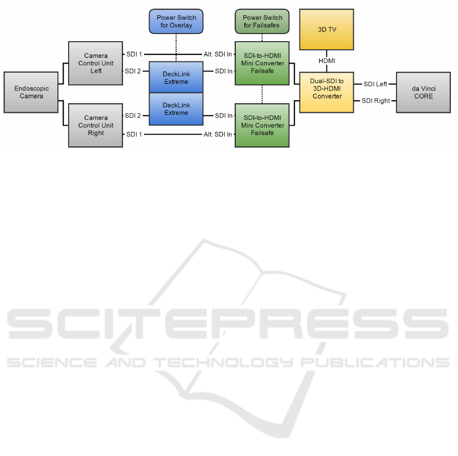
Figure 1: Overview of the setup we use to overlay the video streams of the da Vinci S surgery system with computer graphics
including failsafes and a 3D TV. Grey: standard da Vinci S components. Blue: overlay system (video capture cards in a
computer). Green: Mini-converters used as loss-of-signal switches. Yellow: 3D HDMI conversion and 3D TV.
some tasks (Azuma et al., 2001), thus an additional
100 ms latency is unwanted. The approaches that can
overlay the video streams with low latency only work
with the SD-SDI format of the first generation robot
(Figl et al., 2010) or employed now obsolete and dis-
continued hardware (Hattori et al., 2003).
Our system (Kibsgaard and Kraus, 1999) uses two
2
nd
generation DeckLink HD Extreme video capture
cards to overlay the HD video streams of the da Vinci
S surgical system with computer graphics: one video
capture card for the left channel and one for the right
channel. To generate the computer graphics, we have
integrated the DeckLink API with the popular Unity
game engine. The system generates stereo graphics
using a virtual camera setup that is similar to the en-
doscope of the surgery robot and outputs it through
the DeckLink cards using internal keying (overlay-
ing). The manufacturer of the video capture cards,
Blackmagic Design, claims that the internal keying
introduces less than 1 millisecond of additional la-
tency on the video stream passing through the video
capture cards The hardware setup and connections for
the overlay system are illustrated in detail in Figure 1.
The output of each of the two video capture cards
is connected to separate SDI-to-HDMI converters
along with the redundant output of each camera con-
trol unit of the surgery robot, which are connected
to the converters’ alternate input. In this configura-
tion, the converters function as loss-of-signal switch-
ers that revert the video streams to the original video
signal in case the overlay system malfunctions and/or
is shut down.
The standard da Vinci S surgical system pro-
vides monoscopic monitors for assistants and instruc-
tors. To provide them with a stereoscopic view of
the surgery field and the computer graphics, our sys-
tem also includes a Matrox MC-100 Dual-SDI-to-3D-
HDMI converter which is connected to a 3D TV with
passive stereo glasses. The MC-100 is connected be-
tween the loss-of-signal switchers and the surgeon’s
console to make sure that the 3D TV always shows
the same images as the console. The drawback of this
placement is that the video signals rely on an addi-
tional component even when the rest of the overlay
system is off.
Previous works that measure latency of aug-
mented reality systems with video see-through dis-
plays distinguish between two categories of latency:
photon-to-photon latency and motion-to-photon la-
tency. The first is in some cases also called visual
latency and relates to the time it takes from a pho-
ton entering a camera until a corresponding photon
is emitted and visible on a display. In our case,
that is the latency between light entering the stereo-
endoscopic camera until it is displayed on the sur-
geon console’s displays. Motion-to-photon latency is
sometimes called input latency and is the time from
the user providing an input to a corresponding change
that is visible on a display. As our overlay system only
affects the video streams, measuring the photon-to-
photon latency is sufficient for measuring how much
the motion-to-photon latency is affected by our sys-
tem.
To measure photon-to-photon latency, Jacobs et
al. placed a light emitting diode (LED) in front of a
camera and powered the LED using a low frequency
signal generator (Jacobs et al., 1997). They placed
a photoelectric sensor on the display and connected
it and the signal generator to an oscilloscope. The
photon-to-photon latency could then be determined
by the oscilloscope as the time offset between the two
signals. Because of the discrete nature of video, the
measured latency is dependent on when the LED is
triggered in relation to the shutter of the camera. To
get a representative sample, the measurements have to
be repeated many times. This setup is most useful if
GRAPP 2017 - International Conference on Computer Graphics Theory and Applications
322
only a few setups have to be measured.
To automatically record the measurements, Bliss-
ing and Bruzelius replaced the signal generator and
oscilloscope with a computer (Blissing and Bruzelius,
2015). This makes it possible for the computer to
quickly measure multiple times and correlate the mea-
surements with events and performance of the host
computer. They provide no specifics on the hardware
and software that was used to obtain the measure-
ments. Bachhuber and Steinbach implemented sim-
ilar test equipment using an Arduino Uno microcon-
troller to control the LED and measure the change in
light intensity of the display (Bachhuber and Stein-
bach, 2015). The microcontroller samples the light-
to-voltage sensor at 2 kHz achieving a resolution of
0.5 ms.
Sielhorst et al. proposed a setup that can mea-
sure the absolute latency more precisely with fewer
measurements (Sielhorst et al., 2007). It does so by
recording the display of the augmented reality system
with the camera of the same system. It is then able
to measure the time it takes from the time when the
overlay system outputs an image to the time when the
same image is captured by the camera and it arrives
in system memory. However, as some of the setups
that we are interested in do not pass the image data
through system memory, this approach is not usable
for our system.
3 MEASURING LATENCY
3.1 Test Equipment
To measure photon-to-photon latency of our overlay
system, we have developed test equipment that is sim-
ilar to previously proposed setups (Bachhuber and
Steinbach, 2015; Blissing and Bruzelius, 2015) using
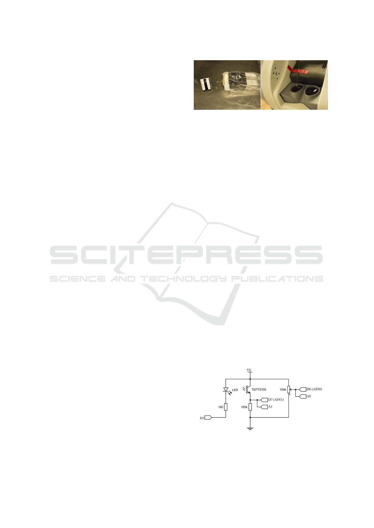
basic electronic components and a microprocessor. A
light emitting diode (LED) controlled by a microcon-
troller is placed in front of the stereoscopic camera
and a high-speed light-to-voltage sensor is placed in
front of the display in the surgeon’s console (Fig-
ure 2). To determine the photon-to-photon latency,
the microcontroller switches on the LED and mea-
sures the time it takes to detect the corresponding rise
in light intensity of the display.
A schematic of the circuit that is connected to the
microcontroller can be seen in Figure 3. The LED we
chose is a high brightness white LED to ensure a sig-
nificant change in intensity of the display. The light-
to-voltage sensor is a visible-light phototransistor in
series with a resistor. The varying voltage from the
sensor is connected to the built-in voltage comparator
Figure 2: Test setup. Left: LED in front of endoscopic cam-
era (without lens). Right: Light to voltage sensor in front of
displays in the surgeon’s console. Both were covered during
measurements to block light from the environment.
of the ATmega328P microcontroller on an Arduino
Uno. This makes it possible for the microcontroller to
immediately trigger and stop timing when the sensed
voltage rises past a set threshold. The benefit of this
approach is that it provides a higher resolution (4 µs
vs. 100 µs) compared to sampling at a fixed frequency
in previous works (Bachhuber and Steinbach, 2015;
Blissing and Bruzelius, 2015). However, this prevents
us from using an automatic threshold adjustment and
filtering (Bachhuber and Steinbach, 2015). The ref-
erence voltage for the comparator (threshold) is in-
stead set by an external potentiometer that has to be
adjusted to match the monitor’s intensity range.
To automate the measurements further, we im-
plemented a simple application that communicates
with the microcontroller via USB (UART). The ap-
plication can start tests and save the results to a file
with a user-specified number of measurements and
file name. To avoid aliasing artefacts, a random de-
lay is introduced between each measurement. The
delay has to be larger than the highest measured la-
tency to avoid triggering on the previous measure-
ment’s intensity change. Source code is available at
https://github.com/Kibsgaard/latency-measurement.
To avoid that other light sources in the environ-
ment affect the measurements, we covered the cam-
era and display with opaque sheets of fabric. This
also makes it possible to set the threshold of the com-
parator lower, which makes the system react faster to
rises in light intensity.
Figure 3: Schematic of the test equipment. The labels are
based on Arduino Uno pin mapping. “A0” and “A1” are
used during calibration.
Measuring the Latency of an Augmented Reality System for Robot-assisted Minimally Invasive Surgery
323
3.2 Overlay Setups
To measure our system’s effect on the photon-to-
photon latency we used the test equipment with the da
Vinci S surgical system where our system is installed
and used during training at Aalborg University Hos-
pital. The installed overlay system uses two Deck-
Link HD Extreme 2 video capture cards, two SDI-
to-HDMI converters and one Matrox MC-100 SDI-
to-3D-HDMI converter. Note that the SDI-to-HDMI
converters are only used as loss-of-signal switchers
and the HDMI signal is not used. The MC-100 out-
puts both a 3D-HDMI signal for the 3D TV and pass-
through SDI signals that are connected to the surgical
system. We measured the latency of multiple com-
binations of the components to investigate their indi-
vidual and combined latency as well as to see if any
combination of the components has an effect on the
synchronization of the signals.
Furthermore, we tested the system with different
DeckLink video capture cards to investigate claims
of slower internal keying (1-2 frames) on some of
the newer generation cards (Jefferson, 2015). In one
setup, we exchanged the DeckLink HD Extreme 2
cards with a DeckLink 4K Extreme card and in an-
other setup with a DeckLink Quad 2 card. Further-
more, we measured the photon-to-photon latency of
the assistant’s monitor both with and without the at-
tached overlay system. The latency of the installed 3D
TV was also measured to compare it to the standard
monitor that is available to the assistants.
With the current setup, the image data from the
video signals is never transferred to the system mem-
ory of the computer that overlays the video streams
with computer graphics. Instead, the computer sends
the computer graphics to the video capture card,
which then overlays the incoming video signal a few
lines at a time and immediately outputs them. Thus,
it is not possible for the system to do any form of im-
age processing on the incoming data (apart from the
alpha blending that is used for overlaying). By using
a DeckLink Quad it is possible to transfer the image
data to system memory, modify it and output it again;
although with a significant latency increase as it has
to wait for a complete frame (33.3 ms) and do at least
two memory transfers.
The newer DeckLink Quad 2 is capable of keying
HD video signals, which makes it possible to input the
image data and process it while simultaneously over-
laying the input signals with computer graphics. Note
that the image data still arrives later in system mem-
ory compared to the signal being overlaid, which re-
sults in delayed graphics in cases where the graphics
rely on information from the processed image data.
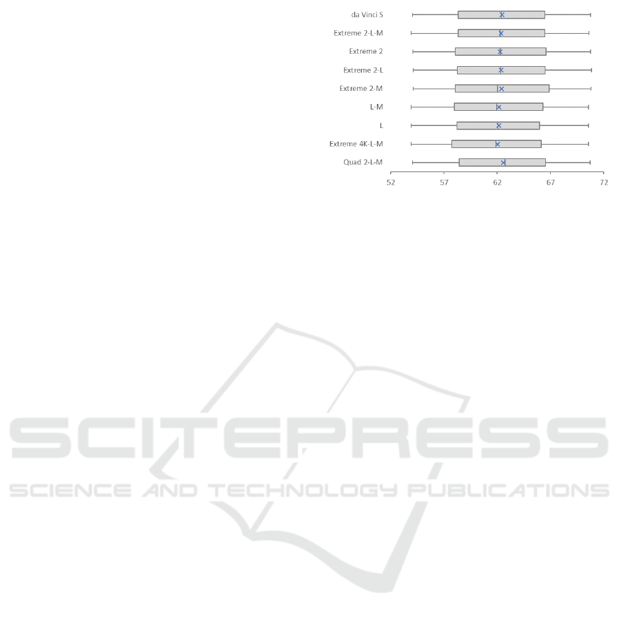
Figure 4: Photon-to-photon latency (in ms) of the da Vinci S
surgical system with various configurations of our system.
(“L” stands for loss-of-signal switchers; “M” for the MC-
100 SDI-to-3D-HDMI converter.) The blue “×” marks the
average latency.
In addition, we also measure the latency intro-
duced by transferring the image data to a graphics
card’s memory, modifying it and copying it back.
This was done using sample code from the Deck-
Link SDK. The overlay system has a NVIDIA Quadro
4000 graphics card, which makes it possible to utilize
GPUDirect. This feature removes one memory copy
operation by giving the video capture card and graph-
ics card access to the same system memory. However,
the image data still has to be copied from the video
capture card to system memory and then to the graph-
ics card’s memory (and back again).
The last setup we measured was using a video
switcher with built-in keying functionality instead of
keying using the DeckLink cards. We tested this with
the Blackmagic Design ATEM Television Studio that
supports downstream, chroma and luma keying.
4 RESULTS
All measurements were performed on a da Vinci S
surgical system, which uses a video signal with a
1080i video format and a refresh rate of 59.94 fields
per second. (One frame of an interlaced video for-
mat consists of two fields.) We measured the in-
herent photon-to-photon latency of the standard da
Vinci S surgical system to be 62.4 ms (SD = 4.7 ms,
N = 1000) with a minimum measurement of 54.0 ms
and maximum of 70.7 ms. As shown in Figure 4,
there were no noticeable differences in measured la-
tency between the surgery system without and with
the overlay system that we presented previously (Kib-
sgaard and Kraus, 1999). This includes different
combinations of components and measurements with
the newer generation DeckLink video capture cards,
DeckLink 4K Extreme and DeckLink Quad 2, which
GRAPP 2017 - International Conference on Computer Graphics Theory and Applications
324
were claimed to introduce higher latency (Jefferson,
2015).
The measurements are evenly spread and stayed
within the duration of one field (16.7 ms). This in-
dicates that the displays of the surgeon’s console are
well synchronized with the camera control units and
none of the setups displayed in Figure 4 disrupted this
synchronization.
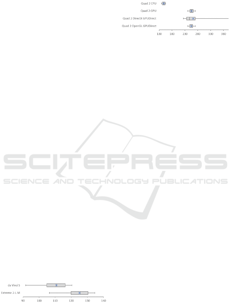
The measurements of the assistant’s monitor
(telestrator) are more spread and here the overlay sys-
tem has a noticeable effect on the photon-to-photon
latency (Figure 5). The latency of the telestrator is
on average 110.7 ms (SD = 8.0 ms, N = 1000) with-
out the overlay system and 125.1 ms (SD = 7.6 ms, N
= 1000) with the attached overlay system resulting in
14.3 ms increased latency.
As shown in Figure 6, passing the image data
through the overlay system’s memory increases the
photon-to-photon latency from the endoscopic cam-
era to the surgeon’s console significantly. By trans-
ferring the image data to system memory, modify-
ing a few pixels using the CPU and immediately out-
putting it through the DeckLink cards, the photon-to-
photon latency is increased by 84 ms to an average of
145.6 ms (SD = 4.9 ms, N = 999). One extreme outlier
(50 ms), which was lower than the inherent latency of
the system, was removed from the measurements. It
is possible that the light sensor was not completely
covered and it got prematurely triggered by changing
light in the environment.
If the data is also transferred to the graphics
card, modified and transferred back, the latency is
increased by 177 ms to an average of 237.7 ms (SD
= 7.8 ms, N = 100). Utilizing NVIDIA’s GPUDi-
rect feature does not reduce this latency significantly
(0.9 ms lower). However, it does reduce the amount
of work the CPU has to do and utilizes asynchronous
readback from the graphics card. As previously men-
tioned, these tests were done using the pass-through
examples from the DeckLink SDK. As shown in
Figure 6, the DirectX example had some very high
latency measurements and dropped several frames,
which caused the displays to blink. The cause of this
is unknown.
Using the keying functionality of the ATEM Tele-
vision video switcher adds close to one field of la-
Figure 5: Photon-to-photon latency (in ms) from the en-
doscopic camera to the assistant’s display. The blue “×”
marks the average latency.
Figure 6: Photon-to-photon latency (in ms) from the endo-
scopic camera to the surgeon’s display when passing im-
age data through CPU or GPU memory. The DirectX setup
dropped some frames and has been purposely cropped in
the plot to better show the results of the other setups. The
blue “×” marks the average latency.
tency when chroma keying (79.5 ms (SD = 5.2 ms, N
= 100)) and two fields (one frame) of latency when us-
ing luma keying (96.2 ms (SD = 4.8 ms, N = 100)) or
downstream keying (96.1 ms (SD = 5.0 ms, N = 100)).
Thus, it is not able to replace the functionality of the
DeckLink video capture cards in our overlay system.
Additionally, we measured the photon-to-photon
latency from the endoscopic camera to the 3D TV
(including loss-of-signal switchers and SDI-to-3D-
HDMI converter) to be 181.9 ms (SD = 5.0 ms, N =
1000), which is 71.2 ms higher than the telestrator
(110.7 ms).
5 CONCLUSIONS
We have measured the photon-to-photon latency of
the da Vinci S surgical system with and without a pre-
viously presented system that can overlay the video
streams with computer graphics. The latency of the
surgery system from the endoscopic camera to the
surgeon’s display was measured to be 62 ms, and the
overlay system has no significant effect on that la-
tency. However, the overlay system does increase the
photon-to-photon latency from the endoscopic cam-
era to the assistant’s display by 14.3 ms on average.
The overlay system consists of two video capture
cards in a computer, two loss-of-signal switchers and
an SDI-to-3D-HDMI converter. The newer genera-
tion video capture card DeckLink Quad 2 can replace
the two cards in the previously proposed system as
it has similar latency, is more accessible, offers more
functionality, and is more compact.
With the current system, the image data from the
video streams is not transferred to system memory
to avoid excessive additional latency. Passing the
data through system memory increases the photon-to-
photon latency to 147 ms and further to 256 ms when
transferred to the graphics card and back.
Measuring the Latency of an Augmented Reality System for Robot-assisted Minimally Invasive Surgery
325

6 FUTURE WORK
Passing the image data from the video streams
through system memory with our current setup is
too slow for real-time interaction, especially in cases
where the graphics card needs to have access to
the data. AMD’s DirectGMA might be faster than
NVIDIA’s GPUDirect, as it enables the video capture
cards to access graphics card memory directly with-
out an intermediate transfer through system memory.
An alternative approach is to use a DeckLink
Quad 2 to overlay the video streams while simultane-
ously using two other channels of the Quad 2 to cap-
ture and process the image data. Future work should
investigate how a system where the overlaid graphics
are delayed affect user acceptance and how to design
around that problem (e.g. by extrapolating motion).
Future work could also involve measuring the la-
tency of video capture cards by other manufactures,
the motion-to-photon latency of the surgical system
and further investigate the increased latency of the as-
sistant’s display when our system is active.
ACKNOWLEDGEMENTS
We thank the staff of the Department of Urology at
Aalborg University Hospital and Minimal Invasiv Ud-
viklings Center for sharing their expertise with us and
providing access to their training system.
REFERENCES
Ali, M. R., Loggins, J. P., Fuller, W. D., Miller, B. E., Has-
ser, C. J., Yellowlees, P., Vidovszky, T. J., Rasmussen,
J. J., and Pierce, J. (2008). 3-d telestration: a teach-
ing tool for robotic surgery. Journal of Laparoendo-
scopic & Advanced Surgical Techniques. Vol. 18, Is-
sue 1, pages 107–112.
Azuma, R., Baillot, Y., Behringer, R., Feiner, S., Julier, S.,
and MacIntyre, B. (2001). Recent advances in aug-
mented reality. IEEE Computer Graphics and Appli-
cations, 21(6):34–47.
Bachhuber, C. and Steinbach, E. (2015). A System for Pre-
cise End-to-End Delay Measurements in Video Com-
munication. IEEE International Conference on Image
Processing (ICIP 2016).
Blissing, B. and Bruzelius, F. (2015). A technical plat-
form using augmented reality for active safety testing.
Road Safety & Simulation International Conference
Proceedings, (October 2015):793–803.
Ellis, S., Breant, F., Manges, B., Jacoby, R., and Adel-
stein, B. (1997). Factors influencing operator inter-
action with virtual objects viewed via head-mounted
see-through displays: viewing conditions and render-
ing latency. Proceedings of IEEE 1997 Annual In-
ternational Symposium on Virtual Reality, pages 138–
145.
Figl, M., Rueckert, D., Hawkes, D., Casula, R., Hu, M.,
Pedro, O., Zhang, D. P., Penney, G., Bello, F., and
Edwards, P. (2010). Image guidance for robotic mini-
mally invasive coronary artery bypass. Computerized
Medical Imaging and Graphics: The Official Jour-
nal of the Computerized Medical Imaging Society,
34(1):61–68.
Hattori, A., Suzuki, N., Hashizume, M., Akahoshi, T., Kon-
ishi, K., Yamaguchi, S., Shimada, M., and Hayashibe,
M. (2003). A robotic surgery system (da vinci) with
image guided function–system architecture and chole-
cystectomy application. Studies in Health Technology
and Informatics, 94:110–116.
Jacobs, M. C., Livingston, M. A., and State, A. (1997).
Managing latency in complex augmented reality sys-
tems. In Proceedings of the 1997 symposium on In-
teractive 3D graphics - SI3D ’97, pages 49–ff., New
York, New York, USA. ACM Press.
Jarc, A. M., Shah, S. H., Adebar, T., Hwang, E., Aron,
M., Gill, I. S., and Hung, A. J. (2016). Beyond 2D
telestration: an evaluation of novel proctoring tools
for robot-assisted minimally invasive surgery. Jour-
nal of Robotic Surgery, 10(2):103–109.
Jefferson, M. (2015). Blackmagic Forum View topic - In-
ternal keyer and channels on Decklink Quad 2.
Kibsgaard, M. and Kraus, M. (1999). Real-time augmented
reality for robotic-assisted surgery. In The 3rd AAU
Workshop on Robotics: Proceedings, pages 19–23.
Aalborg Universitetsforlag.
Kibsgaard, M. and Kraus, M. (2016). Pointing with a one-
eyed cursor for supervised training in minimally in-
vasive robotic surgery. In Lecture Notes in Computer
Science (including subseries Lecture Notes in Artifi-
cial Intelligence and Lecture Notes in Bioinformatics),
volume 9515, pages 12–21. Springer, Cham.
Matu, F. O., Thøgersen, M., Galsgaard, B., Jensen, M. M.,
and Kraus, M. (2014). Stereoscopic augmented real-
ity system for supervised training on minimal invasive
surgery robots. In Proceedings of the 2014 Virtual Re-
ality International Conference on - VRIC ’14, pages
1–4, New York, New York, USA. ACM Press.
Sielhorst, T., Sa, W., Khamene, A., Sauer, F., and Navab,
N. (2007). Measurement of absolute latency for video
see through augmented reality. In 2007 6th IEEE and
ACM International Symposium on Mixed and Aug-
mented Reality, ISMAR, pages 1–4. IEEE.
Su, L. M., Vagvolgyi, B. P., Agarwal, R., Reiley, C. E.,
Taylor, R. H., and Hager, G. D. (2009). Augmented
Reality During Robot-assisted Laparoscopic Partial
Nephrectomy: Toward Real-Time 3D-CT to Stereo-
scopic Video Registration. Urology, 73(4):896–900.
Ware, C. and Balakrishnan, R. (1994). Reaching for objects
in VR displays: lag and frame rate. ACM Transactions
on Computer-Human Interaction, 1(4):331–356.
GRAPP 2017 - International Conference on Computer Graphics Theory and Applications
326
