
Practical Large-scale Model-Driven Development of Business
Applications with an Executable UML
1
Dragan Milićev
University of Belgrade, Faculty of Electrical Engineering, Department of Computing,
P.O. Box 35-54, 11120 Belgrade, Serbia
dmilicev@etf.rs
Keywords: Unified Modeling Language (UML), Model-Driven Development, Rapid Application Development,
Business Applications, Data-centric Applications, Information Systems, Web Applications.
Abstract: Despite intensive work in academy and industry around it in the last two decades, the discipline of model-
driven development with UML apparently has not become the industrial mainstream for building large-scale
information systems. In this paper, we present our attitude toward two probably mostly debated topics: 1)
the lackluster adoption of MDD with UML in this field; we try to identify and explain what we believe are
the main reasons for it, and 2) the controversial debate about general-purpose modeling languages, UML in
particular, versus domain-specific modeling languages (DSLs). We present our approach to building large-
scale business applications based on an executable profile of UML, named OOIS UML, and implemented as
a framework named SOLoist. We also briefly report on our experiences and lessons learnt from successfully
using the approach and the framework in industrial projects of different size and domains over the last
fifteen years.
1 INTRODUCTION
Model-driven development (MDD), as a general
software engineering discipline, along with the
accompanying technologies and standards such as
OMG’s Model-Driven Architecture (MDA) and the
second generation of the Unified Modeling
Language (UML 2.x) have been around for about
fifteen years, but apparently have not become the
industrial mainstream in large-scale development of
information systems, i.e., of business (database)
applications. Although there has been intensive work
in academy and industry around this paradigm, and
model-driven engineering in general is found to be
widespread in industry in general (Whittle et al.,
2014), reports from recent research attempts
indicate, among others, two interesting and to some
extent controversial findings:
1) UML is very poorly adopted in industrial
practice (Petre, 2013; Petre, 2014): out of 50
software practitioners interviewed in the stud
(Petre, 2013), 35 did not use UML at all, 11 used
1
This invited paper is a revised (updated and modified)
version of the paper previously published (in Serbian only) in
the InfoM journal, Vol. 43, 2012, UDC 004.438:004.42.045
it selectively (in a personal and informal way, for
as long as it was considered useful, after which it
was discarded), 1 used to retrofit UML in order to
satisfy management or comply with customer
requirements, while only 3 used it for automated
code generation (which could be treated as kind of
MDD) and 0 used it “wholehearted”, meaning an
“organizational, top-down introduction of UML,
with investment in champions, tools and culture
change, so that UML use is deeply embedded”.
We must say that we were not at all surprised with
these findings, as their fully coincide with our
experience: apart from the few environments
(except from our team) where we have
successfully deployed MDD with UML, we have
not come across any company or team that used
MDD with UML “wholeheartedly”, although
some of the teams used it occasionally and
informally, mostly to comply with customer
demands or for documenting requirements (use
cases or business processes) or sketches of
(usually partial) design. It also seems that the
optimistic bubble around UML on its emergence
in late 1990s have burst as many people got
disappointed with using UML in its early stages
(the reports in (Petre, 2013; Petre, 2014) indicate a
590
Mili
´
cev, D.
Practical Large-scale Model-Driven Development of Business Applications with an Executable UML.
DOI: 10.5220/0006216205900604
In Proceedings of the 5th International Conference on Model-Driven Engineering and Software Development (MODELSWARD 2017), pages 590-604
ISBN: 978-989-758-210-3
Copyright © 2017 by SCITEPRESS – Science and Technology Publications, Lda. All rights reserved

large potion of those being disappointed with
UML).
2) The majority of those who exploit some
kind of model-driven engineering use DSLs,
usually small ad-hoc languages for narrow, well-
understood domains (Whittle et al., 2014).
Although these DSLs are indeed sometimes UML
profiles, it can be concluded that DSLs prevail
over UML as a general purpose language.
In Section 2 of this paper, we explain the
reasons that we deem to be most relevant for the
lackluster adoption of MDD with UML, while in
Section 3 we briefly comment on the debate on
DSLs versus UML. Then, in Section 4, we present
our approach to effective MDD of large-scale
information systems. The approach is based on an
executable profile of UML, named OOIS UML, and
is implemented as an open-source framework named
SOLoist (SOLoist, 2016). Since the OOIS UML
profile has been described in detail elsewhere
(Milićev, 2009), we only outline some of its main
elements and illustrate how it cures the problems
identified in Section 2. In Section 5, we briefly
report on our experiences and lessons learnt in using
the approach and the framework in medium to large
industrial projects over the last fifteen years. In
Section 6 we also comment on some of the other
findings from reports given in (Whittle et al., 2014)
and (Petre, 2013) from our empirical viewpoint. It
should be underlined that we focus on the
development of information systems, i.e., of
business, database (data-centric) applications of
various application domains, especially those with
complex Web-based UIs, which is the domain of our
industrial practice.
2 PITFALLS OF
MODEL-DRIVEN
DEVELOPMENT WITH UML
What we deem the most critical pitfalls of modeling
in general were identified and described long ago in
the seminal book by Selic et al. (Selic et al., 1994),
and were revisited in the context of UML modeling
in a more recent book (Milićev, 2009). (Although
the argumentation given long ago in (Selic et al.,
1994) was sound and reasonable, and are in our
opinion the most relevant reasons for the lackluster
adoption of MDD with UML, it is strange how little
attention and recognition it gains nowadays, even
though the problems described there still persist in
practice in virtually the same form.)
The first generation of UML (UML 1.x) was
almost completely free of formal, executable
semantics. This is because UML, in its initial
conception inherited from some of its predecessors,
was primarily designed as a descriptive language for
specifying, visualizing, and documenting the
construction and design decisions of programs
developed in traditional object-oriented
programming languages (OOPLs). Its scope of
applicability was intended to be very wide: UML
was designed to be used for specifying programs
implemented in a variety of programming languages
and for very different application domains, partly
because UML was a synthesis of many other
modeling predecessor methods. While UML
provided some rough hints about the intended
meaning of its concepts (mostly derived as
generalizations of the concepts found in different
OOPLs), the precise interpretation of the semantics
of UML models was almost completely left to the
way the models were mapped to the target
implementation language. Obviously, such
interpretation was highly dependent on the
semantics of the target language, as well as of the
mapping. Consequently, UML models were
semantically ambiguous. It was completely up to the
creativity and discipline of a development team to
impose a certain unambiguous semantic
interpretation of UML models in the domain of their
interest.
When information systems are concerned in
particular, such usage assumes the following. Most
UML tools can easily generate the relational
database schema (DDL) as well as the class
definition code in a target OOPL from a UML class
model. However, the coupling between the space of
objects of the OOPL and the data in the relational
DBMS (RDBMS) is typically left to a separate
object-to-relational mapping (ORM) framework,
such as Hibernate or similar. Such ORM
frameworks, on the other hand, do not have anything
to do with UML and its semantics, especially with
action semantics, but provide the semantic coupling
between the OOPL and the RDBMS. In addition,
such coupling often assumes that the database
schema is developed separately and independently
from the OOPL class structure.
2
This means that the
database schema is designed from the conceptual
2
In the extreme, some methods advocate the so called
code-first or DB schema-first approaches, where high-
level models, such as Entity-Relationship or UML class
models are obtained by reverse-engineering of already
designed programs or database schemas.
Practical Large-scale Model-Driven Development of Business Applications with an Executable UML
591

(data) model of the problem domain and optimized
for particular data access patterns according to the
traditional practices of relational database
normalization and optimization, while the OOPL
code is designed according to the practices of object
design. The task of an ORM is then to couple these
two. In addition, ORMs often make it explicit to the
developer that an OOPL object that resides in
(volatile) operating memory and its (persistent)
database representation are two distinct entities that
have to be linked (typically over an object ID) and
kept in sync by the ORM’s mechanisms. These
mechanisms typically burden the developer with
having to be aware of the “lifecycle” of the memory
object and taking care of issuing the proper calls to
the ORM, such as to “save,” “load,” or “discard” the
memory object. This is one drastic example of
unnecessary accidental complexity imposed by the
imperfect technology of coupling two semantically
different spaces (OOPL and RDBMS).
A very similar situation is when the OOPL
semantic space is coupled with the application’s
presentation layer. Most user interface (UI)
frameworks and libraries couple the presentation
semantic space (e.g., HTML for Web-based UIs)
with the OOPL space; this simply means that the UI
components are constructed to work with memory
objects that have the semantics of the OOPL. With
more or less success of that coupling, virtually all of
the popular approaches do not have any connection
or provide any semantic coupling with UML and the
application’s model. Yet again, the developer has
very often to be aware of the purely technological
implementation details, such as the separation
between the Web page vs. the backing
bean/controller object, the client code vs. the server
code, the business layer vs. the entity (data) object,
etc.
With all this linguistic and semantic
heterogeneity imposed by the mainstream
development technologies, the OOPL code typically
appears to be the central artifact, “the semantic
master” to the semantics of which all other artifacts
are adapted. This holds for the UML model too. In
such circumstances, the model becomes just an
additional and unnecessary burden: it is rather
pointless to draw UML diagrams just to obtain
skeletons of classes in OOPL code. In fact, UML is
used just to “sketch and draw the code.” Apart from
somewhat better clarity of the relationships between
classes, due to diagrammatic visualization, this
brings little or no additional value; quite the
contrary. The very semantic heterogeneity, on the
other hand, is a big problem for itself even without
using UML models (Groenewegen et al., 2010), and
is a typical example of undesired accidental
complexity.
As an effect, developers typically exhibit the
“rush-to-code syndrome”: “a pervasive unease
during the early development phases, a prevailing
attitude among the developers that requirements
definition and design models are ‘just
documentation,’ and a conviction that the ‘real
work’ has not begun until code is being written”
(Selic et al., 1994). Although they would claim that
requirements and design models provide useful
insights into the nature of the system being
developed, the more time is invested in building
such models, the more uncertainties multiply. This is
caused by the lack of objective evidence that the
developed model is correct and complete.
As a result, once the development passes to the
implementation phase, the requirements and design
models remain as documentation artifacts only,
without executable semantics or any effect on the
ultimate executable system. When the development
process is iterative and incremental, it often calls for
modifications. Such modifications on the initial
design model are not enough to upgrade the running
system and therefore, the developers are not forced
to update it properly. Instead, they update what they
merely have to – the implementation, i.e., the
relational data definition code and the OOPL code,
which directly affect their running system. This
ultimately leads up to inconsistencies between the
design model and implementation, which turns the
design model into incorrect and thus harmful or at
least useless documentation. To illustrate this, we
cite a comment reported in (Petre, 2014): “Other
[UML modeling] tools I’ve used... always end up
being dropped after the initial thought stage simply
because they end up being too painful to keep
tweaking in order to sync the diagrams with code
changes.” This often forces the development teams
to discard the models and stick only to the
implementation in later iterations. The reports in
(Petre, 2013; Petre, 2014) indicate a large potion of
those using UML this way; for example, one rather
common opinion is quoted in (Petre, 2014): “For
large, complex software projects, with continuous
delivery, UML would slow down practice
continually... The fastest software development
teams don’ t use UML.”
The essence of the described problem is called
the semantic discontinuity and is well described in
(Selic et al., 1994), (Milićev, 2009): it is the lack of
formal coupling between the representations of
different kinds of related detail, as we have
IndTrackMODELSWARD 2017 - MODELSWARD - Industrial Track
592

described. The central artifact that imposes the
unambiguous semantic interpretation is the code,
while the model is not the central, authoritative
specification of the software and its semantics is
interpreted via the semantics of the obtained code.
This is certainly not the idea of MDD, where models
are considered to be central artifacts of development
from which all other artifacts are derived or
subordinate.
The problem of the lack of formal, executable
semantics was recognized and tackled by the
emergence of the second generation of UML 2.x
(UML 2.5, 2015) and especially by the Foundational
Subset for Executable UML Models (FUML)
initiative of OMG (FUML 1.2.1, 2016). The latter
initiative has the objective to identify a subset of the
UML 2 metamodel that provides a shared foundation
for higher-level UML modeling concepts, as well as
to define a precise definition of the execution
semantics of that subset. It is expected to cure the
described essential problem of the lack of executable
semantics of the core UML concepts.
Unfortunately, nothing has changed in the
mainstream yet. The FUML initiative seems to be
still new and not yet widely supported by tools and
frameworks. It is even less recognized in the wide
development community. In addition, FUML
provides a general-purpose programming platform
that should be carefully profiled for various problem
domains. For example, some UML concepts are not
so important or necessary in building information
systems, while the development of UI is of major
importance and typically consumes most of the
development resources. This has been also
recognized and addressed by a most recent OMG's
standard named Interaction Flow Modeling
Language (IFML) (IFML 1.0, 2015). Being very
new, it has very modest recognition yet. However,
building large-scale information systems requires
much stronger concept and tool support, covering all
typical and important needs of this domain, such as
querying of very large object spaces, massive and
scalable concurrent and distributed processing,
concurrency control (isolation) and transactions, etc.
As a result, developers still use UML as before,
selectively and informally, or do not use it at all
(Whittle et al., 2014; Petre, 2013; Petre, 2014).
MDD as a discipline, especially with UML, with its
accompanying tool support, still seems to be
immature at least for the information system
domain.
3 UML VS. DSL
On the other hand, the report (Whittle et al., 2014)
indicates that MDD is more widely applied with
DSLs instead of UML. This claim contributes to the
recent very intensive debate on UML (as a general-
purpose language) vs. DSLs. Without any ambition
to resolve this dilemma, we would like to put
forward some arguments based on our experience
with the approach we successfully apply in the given
domain (some of these being in accordance with the
reports in (Petre, 2013)).
Our main conjecture is that the reason for the
apparent prevalence of DSLs over UML (Whittle et
al., 2014) may not necessarily be inherent in the very
nature of these languages (domain-specific vs.
general), but is due to several other facts.
First, and maybe most important, is the presence
of the proper semantic coupling, coherence, and
formality of the language that is necessary for
success, as already discussed. In the first instance, as
described, UML lacks them in many parts. However,
this can be solved with proper profiling of UML and
with adequate tooling, as in our example. Making a
small, semantically coupled and well defined DSL is
presumably much easier than profiling UML in that
way.
Second, it is about the context: DSLs usually put
their concepts in a very specific context of a
particular domain, while UML does not by default,
but this can also be done by profiling though. The
need for context is also mentioned in (Petre, 2013;
Petre, 2014), the lack of context being one of the
main reasons for disappointment with UML.
Third, it is about the size and complexity of the
language: UML is often accused of its extreme
volume, complexity, and heterogeneity, which is
indeed true. In order to make it practical, one has to
narrow its scope by selecting only a subset of
concepts and features that are useful for a particular
usage (domain, team, or project). This is again what
profiles are meant for: UML is intended for selective
use, as opposed to a common misconception that its
selective use is wrong or against its spirit (Petre,
2014). A DSL is, on the other hand, usually by its
design confined to the selected (typically small) set
of necessary concepts.
UML is very broad, and although its size and
complexity may really be treated as its drawbacks,
they can also be taken as its potential, because it can
be profiled for many different purposes. Its concepts
are so diverse that one can very likely find a concept
that fits into particular needs in the given context.
Indeed, the report in (Whittle et al., 2014) confirms
Practical Large-scale Model-Driven Development of Business Applications with an Executable UML
593

that some DSLs used in practice can be defined as
UML profiles; IFML (IFML 1.0, 2015) and our DSL
for user interfaces (Milićev and Mijailović, 2013)
are additional good examples of rather exotic DSLs
that can be expressed as UML profiles.
However, shaping a DSL into a correctly
defined UML profile is not an easy task. In order to
recognize the UML concepts that the conceived
domain concepts fit into, one has to be an expert in
UML and know its metamodel and semantics,
including semantic variation points, and to
understand the mechanisms of extending and
profiling UML. It is thus often the case that defining
a DSL from scratch with a powerful tool like
(Tolvanen and Kelly, 2015) can be much easier.
One should not totally give up profiling UML in
favor of developing a DSL from scratch though,
because staying within the boundaries of a standard
language has many advantages: modeling tool
support and model portability (interchange);
modeling is more likely to be understood and
adopted by newcomers and people external to the
team, because they are more likely to be educated
and trained with a standard language than with an in-
house DSL; better potential for reuse of profiles for
different projects, products, or even domains, etc.
4 MDD WITH SOLoist
We now briefly describe how MDD looks like in a
semantically homogeneous and coherent
environment of SOLoist.
Coupling of Structure and Behavior
Once the UML class model of a problem domain,
like the sample one shown in Figure 1, is developed
using an ordinary UML modeling tool, SOLoist
generates all necessary artifacts for the application
automatically. This includes the relational database
schema, as well as the code in the target OOPL used
for implementation (Java in this case). The
generated code is linked with the SOLoist runtime
Figure 1: A sample UML model.
environment, which provides the necessary UML
action semantics and ORM, in a manner of a UML
virtual machine.
Objects that are instances of the modeled
classes, as well as their attributes and links as
instances of the modeled associations, comply with
the UML semantics and are inherently persistent. An
object is a single and coherent entity, and there is no
any semantic distinction between its memory and
database representations, nor is the latter visible or
accessible to the application by any means.
3
This is
manifested by the way the object space is managed
with actions. Actions are written in the notation of
the hosting OOPL (Java in this case). For example,
an object of Employee is created with a create object
action that is simply written as:
Employee anEmpl = new Employee();
Although the notation is (intentionally) exactly the
same as the one in Java, this is not the case with the
semantics. The created object is inherently persistent
and lives until it is explicitly destroyed by a destroy
object action; this can happen much later,
independently of the execution of the program that
created the object:
anEmpl.destroy();
There is no need to save or load an object, or to deal
with any kind of “persistence managers,” “entity
objects,” “sessions,” object IDs, or other kinds of
elements as in other ORM approaches.
Values of objects’ attributes are accessed via
read and write attribute value actions. For example:
anEmpl.name.set(new Text("John Doe"));
...
if
(anEmpl.dateOfBirth.val().isEqualTo(Date.tod
ay())) ... // Happy birthday!
As it can be seen, reading or writing attribute values
are explicit actions invoked through operations from
the SOLoist API of the runtime environment (val()
and set() in this example). The API offers a full
set of operations on attribute values, supporting the
semantics of multivalued attributes from UML, with
optional ordering. This is somewhat different from
the concealed actions in an OOPL, where read and
write actions are implied from the position of a term
within an expression (e.g., an assignment implies a
write action to the left-hand side operand).
The similar holds for managing links of
associations. For example:
3
This is why we use the term object space instead of
database.
IndTrackMODELSWARD 2017 - MODELSWARD - Industrial Track
594

anEmpl.dept.set(aDept);
creates a link between the objects referred to by
anEmpl and aDept. After that, the object referred to
by anEmpl will be a member of the collection
returned by the action that reads the slot
aDept.members.
The behavior is specified within methods of
operations. The methods are written in Java code,
which may include all available Java control flow
structures (conditions, loops), expressions, and
statements. The access to the object space is
linguistically embedded by means of the API for the
actions, as already described. In addition, methods
can call operations of objects with the usual
operation call semantics in Java, including argument
passing and polymorphism. References to objects
are ordinary Java references and comply with the
usual Java typing rules (e.g., conversion). The only
trick is that those references refer to proxies that
provide the described action semantics and access to
the data values that are stored in the database and
cached in memory outside these proxies. However,
this is a matter of the implementation and is
completely hidden from the developer.
The developer does not need to make any
intervention or configuration in order to achieve the
described semantics. As in Ruby on Rails
(Viswanathan, 2008), we prefer convention over
configuration. The relational database schema is
obtained by a default set of ORM rules. For the
purpose of performance tuning for large-scale
information systems and huge object spaces, we
provide a set of configuration options that can adjust
the ORM if necessary. However, this fine tuning can
be done completely independently from the
application development, as it does not affect the
model and the action code within methods. The
entire ORM, the synchronization between the cached
objects in memory and their database
representations, as well as the semantics of UML
actions, including concurrency control (isolation on
the object level, not on the record level) and
transactions, is provided by the SOLoist runtime.
We also support hierarchical UML state
machines for modeling life cycles of objects. As a
special feature, our state machines allow triggerless
transitions, making state machines cover the
semantics of classical flowcharts (because the
control flow can leave the state as soon as its action
ends and branch over decision vertices). Hierarchical
state machines are not interpreted by the runtime,
but Java code is generated from them, making the
implementation efficient. We also support
submachines with entry and exit points, as a very
powerful concept for abstraction, decomposition,
and high-level behavioral polymorphism. This way,
we do not have to support UML activities, as most
of the practical needs for modeling complex
behaviors and business logic can be handled by state
machines.
To support large-scale processing of huge object
spaces and especially lifetimes of objects modeled
with state machines, our framework provides the
notion of so-called agents. Agents are (profiled)
active classes, whose instances are concurrent
threads that process parts of object space. Each agent
(as a class) can be configured with a query that
selects a number of objects (e.g., objects residing in
a certain state). The class can be automatically
instantiated in a configurable number of concurrent
instances that partition the selection of objects for
concurrent processing. Each of the instances, in each
of its processing iterations, takes a chunk of its own
partition of objects (by executing the query) and
performs the polymorphic operation upon each
object; this can, but need not be, result in a call of an
operation of the target object, or triggering its state
machine. If the partition is empty, the agent instance
goes to sleep for a while and then re-executes the
query to fetch a new chunk of objects.
The combination of these two notions,
hierarchical state machines (as a general UML
concept) and agents (as a profiled, domain-specific
notion) provide a very powerful vehicle for abstract
modeling and efficient and scalable concurrent
processing, again thanks to proper semantic coupling
and domain-specific profiling.
Querying
An important feature of a technology for building
information systems is the possibility to pose
complex queries in order to perform searches or
make reports. For that purpose, we provide a variant
of the ODMG’s Object Query Language (OQL).
OQL inherits the syntax flavor of SQL, but supports
the object data model. Our variant of OQL is
adapted to UML. Its syntax and semantics is fully
described in (Milićev, 2009) and briefly
demonstrated here.
For the sample model previously shown in
Figure 1, in order to retrieve the names and dates of
birth of all employees of the ‘R&D’ department, one
can write in our OQL:
SELECT empl.name, empl.dateOfBirth
FROM Department d, d.members empl
WHERE d.name=’R&D’
Practical Large-scale Model-Driven Development of Business Applications with an Executable UML
595

It can be seen that an OQL SELECT query, in its
FROM clause, uses navigation terms (e.g.,
d.members) over objects and links, instead of
joining relations as in the relational algebra. The
difference is especially noticeable when the
navigation has to be done over a many-to-many
association. The OQL query looks the same as
shown above, while the equivalent SQL query has to
join three tables (two for the entities on the ends and
one for the many-to-many relationship). The more
complex the navigation in the query, the bigger the
difference between the OQL and SQL counterparts.
OQL supports inheritance and polymorphism.
For example, the following query includes the
access to the inherited properties name and members
of the class Headquarters:
SELECT hq, hq.name, empl, empl.name
FROM Headquarter hq, hq.members empl
The following query will return the set of all
departments that have members having ‘John’ in
their names; the set will include headquarter(s) too:
SELECT dept
FROM Employee empl, empl.dept dept
WHERE empl.name LIKE ’%John%’
Our OQL supports specialization, too. If we want to
retrieve only headquarters that have members having
‘John’ in their names, we can write:
SELECT hq
FROM Employee empl, empl.dept:Headquarter hq
WHERE empl.name LIKE ’%John%’
The result of a query is a collection of tuples
that can be iterated in the Java code or directly
rendered by UI controls. The references to objects
and values returned in the components of tuples can
be used as already described.
Our OQL supports many other features, like
aggregate functions in the SELECT clause,
equivalence for outer joins, GROUP BY, ORDER BY,
and HAVING modifiers, unions and subqueries, and
parameters of queries.
Another particularly important and useful
querying feature is the query builder, an API that
allows declarative definition of (an internal
representation of) queries that may have dynamic
form, based on the presence or absence of certain
query parameters. This is necessary to support
complex searches required in typical applications.
For example, a typical search for employees in our
running example would allow an optional criterion
to select only those employees that are assigned to a
certain department, and satisfy some other optional
criteria (in terms of attribute values of employees or
departments). If the search includes the criteria
related to the department of the employee, then the
underlying query should have a navigation term in
the FROM clause that joins the employee with the
department (Employee e, e.dept d), and
another term in the WHERE clause that filters only the
requested department(s); if the search does not
include criteria related to the department, the FROM
and WHERE clauses should not include these terms.
This dynamics of the query form is not easy to
achieve via usual programming approaches,
especially not by direct manipulation of a textual
representation of the query. On the other hand, the
declarative approach with the query builder makes
definition of very complex and dynamic forms of
queries rather straightforward, as it hides the
complexity of the dynamics from the developer.
Coupling with UI
Typically, the most resource-consuming part of
information system development is development of
UIs. In order to reduce accidental complexity and
ensure a proper impedance matching, our framework
provides a full semantic coupling between the object
space and the UI by using a novel paradigm for
building UIs. It is briefly presented here, and
described in details elsewhere (Milićev, 2009),
(Milićev and Mijailović, 2013).
The motivation behind our paradigm is
illustrated in Figure 2. A simple UI form from the
sample application whose model was previously
shown in Figure 1 works as follows. The tree view
on the left in Figure 2a is configured to render the
hierarchy of departments. The three UI controls on
the right display the properties of the department
currently selected in the tree view. The first two
controls are editable text boxes that render and edit
the name and description attributes of the class
Department. The third control is a list box that
displays all employees who are members of the
selected department.
The behavior of the UI controls can be
abstractly described like this. Whenever an object of
Department is selected in the left-hand tree view,
each of the three right-hand controls has to display
the value of the corresponding slot of that object
(name, description, or members – the collection
of linked objects of Employee). Obviously, the
object of Department selected in the tree view has
to be dynamically provided as the input parameter of
each right-hand control. Thus, the property (attribute
or association end) of the class Department whose
value will be displayed by each of these three right-
IndTrackMODELSWARD 2017 - MODELSWARD - Industrial Track
596
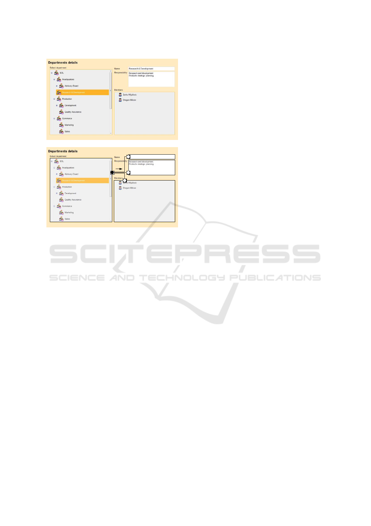
(a)
depts members : SlotEditorComponent
resp : SlotEditorComponent
name : SlotEditorComponent
(b)
Figure 2: (a) An example of a form with coupled UI
components. (b) The message passing perspective to the
functional coupling of UI components.
hand controls can be configured at design time,
when the UI is being constructed. On the other hand,
what changes dynamically, by user’s actions, is only
(a reference to) the object of Department whose
slot (as an instance of the configured property) has
to be displayed.
By such observation we come to the perspective
depicted in Figure 2b. The UI controls can be
logically regarded as components with pins that
form their interfaces. A pin is a connection point
through which a UI component can send or receive
signals or data to or from other components. For
example, the tree view has one output pin through
which it sends a reference to the object selected in
the tree view each time the selection is changed; of
course, this selection is changed dynamically, by
user’s actions. Each of the three right-hand
components has one input pin that accepts a
reference to the object whose configured slot the
component will display and edit. The internal
behavior of the control ensures that each time a new
value occurs on its input pin, the control accesses the
underlying object space by reading the
corresponding object’s slot and reflects its current
value on the screen.
In order to ensure the proper functional coupling
of these components, the developer simply has to
connect the output pin of the tree view component to
the three input pins by wires. Wires specify the
connections through which data will flow from an
output pin to one or more input pins, whenever a
new value is provided on the output pin, as shown in
Figure 2b. The components are created as objects
and wired through the SOLoist Java API or through
models as described in a DSL that is defined as a
UML profile (Milićev and Mijailović, 2013).
SOLoist provides a rich library of built-in UI
components for Web-based applications. These
components, on one hand, wrap around usual UI
widgets, such as textboxes, checkboxes, combo
boxes, lists, tree views, pictures, grids, and many
more, providing a usual appearance and behavior to
the user, as well as interface pins to other
components. On the other hand, these components
raise the level of abstraction and directly match with
the underlying object space with the UML semantics
(Milićev, 2009).
As another illustrative example, we present the
UI component shown in Figure 3. The component
shown in Figure 3 is an editor of a slot of an object
provided on its elem input pin. In the presented
example, the object is an instance of the class
Employee. Let us refer to it as the host object. The
slot is an instance of an association end from the
UML model. The association end is configured as a
construction parameter (and stored in an attribute) of
the component. In this example, this is the
association end dept that maps an employee to its
department. The component shows a collection of
objects of a certain class that are candidates for
creating links with the host object over the
configured association end (dept). The component
can be configured to show this collection of objects
as a list, obtained from a collection given on another
pin, or as a tree, with the object given on another pin
as its root and the tree spanned over the links on the
given association end (subdivisions in this case).
Whenever a new Employee host object arrives on
the elem input pin, the component fetches the link
(or multiple links in a general case) of the host
object on its dept slot from the underlying object
space and updates the checkboxes to reflect this link
(or multiple links in a general case). Whenever the
user changes the state of the checkboxes, the
component updates the underlying object space by
creating or deleting the links. As a result, in order to
provide this typical behavior, the developer has
nothing to code in a traditional way, i.e., in
imperative code of components’ event handlers;
Practical Large-scale Model-Driven Development of Business Applications with an Executable UML
597

everything is done declaratively, by configuring the
(construction parameters of) the component and
connecting its pins with pins of other components in
its environment.
Figure 3: A sample UI component for editing an
association end instance.
Our library is full of sophisticated components
that follow the same paradigm. Their
implementation is Web-based. The Web client tier
implements the entire UI layer, while the object
space layer resides on the Web server. The client tier
uses Google Web Toolkit (GWT) as its
implementation platform. In particular, the off-the-
shelf components from our component library wrap
up GWT widgets. The client tier accesses the object
space via AJAX calls: whenever a component has to
fetch or modify a piece of the object space, it issues
an AJAX call, concurrently and independently of
other components. Obviously, the reflectivity of the
underlying UML object space plays a significant
role in this paradigm, since the domain object space
is accessed through UML reflection.
5 EXPERIENCE
We conceived the described MDD approach in early
2000. Since then, we have developed four
generations of the framework in different languages
(Visual Basic, C++, and Java), and on different UI
platforms and architectures (Desktop: Visual Basic,
MFC, Qt; Web: GWT). These four generations had
different sets of features, levels of semantic
integration, and internal architectures and design.
Using these four technology generations, we have
implemented a few dozens of commercial, industrial
projects of different size and from very different
application domains, some of them resulting
governmental systems of national scale.
4
We will
here briefly report on our experiences collected and
lessons learnt from this practice.
The main conclusion from our experience is that
MDD really works and scales quite well for all sizes
of projects, provided that it is applied properly and
in a framework that ensures the proper semantic
coupling as in our approach.
We have also confirmed many other claimed
benefits of applying MDD and using a semantically
coherent environment. The accidental complexity is
much reduced as compared to other mainstream
approaches that are linguistically or semantically
heterogeneous. This leads to more concise, but also
more expressive development artifacts (model and
code) due to the use of more abstract modeling
concepts.
As a result, the development cycle becomes
shorter. This claim is difficult to quantify and prove,
and we do not tend to do that here. Although we
have not conducted experiments of independent
development of the same systems by different
approaches, because we focused on real-life,
industrial projects that had very tight deadlines, we
can say that our clients, as well as partners who were
professionals experienced and trained in many other
popular mainstream frameworks, were pleased with
the complexity of the developed systems compared
to the achieved performance and delivery time.
Our experience also fully corroborates the
statements given in a paper on the pragmatics of
MDD (Selic, 2003), especially about the benefits
and importance of automation, standards, model
executability, and integration with external and
legacy systems.
We also agree with the conclusions on the
importance of education and training (Selic, 2012),
as well as of the skills for abstract thinking (Kramer,
2007). From our experience of training in general
and for our MDD in particular, we have found that
the existence of runtime semantics is the key to
successful adoption of new abstract concepts by
engineers. If a concept has precisely defined, clear,
and observable effects at runtime, so that one can
immediately experiment with it, then it is more
likely to be quickly adopted, even without too
detailed and formal explanations. It is the same case
as with learning any other classical programming
language or environment, where new concepts are
typically introduced with examples that
4
A selection of these projects can be seen in the Case
Study section at www.sol.rs.
IndTrackMODELSWARD 2017 - MODELSWARD - Industrial Track
598

programmers can immediately experiment with
(“hello world” is the classical ultimate and trivial
example of this approach). Explaining runtime
effects of a concept can be treated as a kind of
operational approach to teaching and understanding
semantics. One simple example can be the
explanation of the concept of a pointer: taken
abstractly and in an operational way, one can
explain it by defining the meaning of the operations
with the pointer (linking it with an object,
dereferencing it). Another example from our domain
is the notion of a link between objects, as an instance
of association, described in terms of actions on links
and linked objects.
On the other hand, when a clear description of
runtime semantics is missing, the concept becomes
difficult to comprehend or remains unclear. In such
cases, the alternative way people usually take to
understand the concept is to map it to already known
concepts (usually in a different semantic domain,
that is, different language), i.e. to something the
semantics of which they are already familiar with.
This is a kind of denotational approach to capturing
semantics. Although this can also be a viable and
correct approach that can help with understanding, if
treated carefully and in the right way, it can also be
misleading, as already explained, as the semantic
domain it is usually mapped to is the implementation
(OOPL, relational, etc.). To take the previous
examples, a denotational approach for teaching the
semantics of pointers could explain its
implementation in terms of an operating memory
cell containing the address of another memory cell
where the pointed object is located, while a link can
be explained with how it can be implemented in an
OOPL via pointers (references) between linked
objects.
One important characteristic of our method and
framework is its adherence to the basic principle of
software design – localization of design decisions.
Namely, it has turned out in practice that the number
of ways in which a certain requirement can be
implemented or retrofitted to an existing application
is limited to only few or one in most cases. This is
good, because the implementation becomes
straightforward and independent of the developer
who makes it, while the applications are easier to
understand and maintain.
As a special case of this principle, one piece of
design can be maintained at only one place, either
code or model in most cases. For example, although
theoretically possible, the approach makes it
extremely difficult to make any change to the class
structure of the system, such as to introduce a new
(persistent) class or change any detail of an attribute
of a class, in the generated code, because it will not
guarantee the full consistence of all artifacts (the
UML reflection, the database schema) and ensure
proper functioning of the system. In fact, such a
change is almost as difficult and unreliable as
changing a piece of binary code produced by a
compiler. For that reason, it is much easier and
secure for the developer to follow the strict
procedure of changing the relevant piece of model
only and regenerate all other implementation
artifacts automatically. The similar holds for state
machines. Consequently, we do not exploit reverse
engineering and round-trip engineering (generate the
code from the model, tweak the code when a small
change is necessary in the running system, and then
reverse engineer the code to update the model in
order to keep it in sync): we find round-trip
engineering inappropriate, and reverse engineering
useful only for the purpose of extracting information
from legacy systems to understand their design, and
not as a tool for round-trip engineering in
developing new systems.
As a proof of our claims, we give the only
exception to this rule that represents a weak point of
our framework: operations of classes can be
specified in model as well as in sections of code
preserved by the code generator. And as soon as it is
possible to do one thing in different places, different
people will really do it in different places: some
define operations in the model, while the others take
the much easier and quicker approach and define
operations in the code, resulting in not fully
complete models (but without any impact on the
executable software). Although this weakness does
not represent a big problem in practice, we plan to
tighten it up by better coupling of the modeling and
coding environments in the future.
Not surprisingly, we have often been faced,
especially in the early period of our practice, with
“one of the first questions asked about MDD: how
the automatically generated code’s efficiency
compares to handcrafted code” (Selic, 2003). This
is definitely one of the fears of pitfalls of MDD most
frequently expressed by customers and partners,
especially managers, having no experience with
MDD. MDD or any other highly abstract and
reflective approach is often accused of introducing
additional and unacceptable overhead, especially in
terms of execution time or space consumption, as
compared to more traditional approaches.
Our reply is also classical: “This is nothing new;
the same question was asked when compilers were
first introduced. The concern is the same as before:
Practical Large-scale Model-Driven Development of Business Applications with an Executable UML
599

humans are creative and can often optimize their
code through clever tricks in ways that machines
cannot. Yet, it is now common knowledge that
modern optimizing compilers can outperform most
practitioners when it comes to code efficiency.
Furthermore, they do it much more reliably (which
is another benefit of automation)” (Selic, 2003). We
would add that the same situation was with Java in
its early stages, when it was suspected of “being
much slower because it is interpreted by a virtual
machine;” nowadays, real-time and embedded
software runs on JVM.
Our practice has shown that efficiency problems
may arise, but that the automation and abstraction
can also provide the right means and place to solve a
problem in a generic way, without affecting the
application, because the problem and its solution can
be localized in the runtime or the code generators
and thus isolated from the application. One such
problem arose in one of our large governmental
projects, which had to handle an object space with
hundreds of millions of objects and with temporal
dimension (i.e., keeping all versions of modified
objects and links). At the beginning, some large-
scale queries in the system suffered from
performance problems. This forced us to dig deeply
into the problem, and as a result, we conceived some
advanced optimizations, such as placing redundant
values in the database or avoiding unnecessary joins
in queries. Once we have implemented the
optimizations in our query translator and ORM, the
achieved performance was often even better than
what could have been achieved with manual coding
or with a purely relational approach (and orders of
magnitude better than initially). Namely, the
redundancy is handled in a generic way, by the
ORM only, and is completely transparent to the
application; if it had been done manually, it would
have been very difficult to design the schema
consistently and then maintain the redundant data
copy on every write action, or to optimize each
critical query. On the other hand, unnecessary joins
are very difficult to identify manually (while the
algorithm behind is not so complex), and is not
automatically feasible on the relational database
level, because this level of abstraction lacks the
necessary information about the semantics of
relationships that are known to the more abstract,
UML model level. This experience has also opened
a completely new field of our ongoing research that
investigates even more sophisticated and aggressive
optimizations that are completely impossible to
implement manually and on the level of a relational
model.
Our second example is related to state machines
and massive processing of objects by agents.
Initially, we used to store the current state of an
object in its textual attribute, encoding the fully
qualified name of the state (note that it can be nested
within other states or submachines). Such encoding
is very convenient, because it allows for flexible
searching of objects residing in different composite
states (making composite states a kind of
abstraction, union, or generalization of nested
states), by simple substring expressions in queries
(searching for state names having a certain prefix).
However, when agents select their chunks for
processing, such queries can be very inefficient in
case of huge object spaces. We have thus found
another approach that benefits from both sides:
objects can still be searched for states using path
prefixes (composite states), but the queries are
orders of magnitude more efficient, because they
rely on integer search.
In order to be successful, an MDD approach for
a particular domain has to be full-fledged and cover
all typical situations and support practical needs that
may occur in practice (Selic, 2003), (Selic, 2012). In
our case, one typical situation is the following.
During development, until production, it is easy to
regenerate the entire database schema each time the
source UML model evolves. However, once in
production, the database contains valuable user's
data that have to be preserved and the database
cannot be simply regenerated from scratch, but has
to be carefully updated to ensure data preservation.
Although manual maintenance is possible, it is
tedious and error-prone, especially in case of
complex models/schemas. For that purpose, we have
designed a tool to solve this database schema
evolution problem (Milovanović and Milićev, 2015),
which is invaluable in our practice. A second
example is a complex UI component designed to
render results of complex queries, typically used for
already described searches. It is, of course, coupled
with the query builder. Our framework is full of
such examples, and even more will come in the
future.
Finally, it is of utmost importance to preserve
pragmatism in real-life situations. Although we
advocate an “orthodox” approach to MDD, as
briefly described here and in (Milićev, 2009), this
does not mean that it has to be dogmatic or
restraining in any way. An MDD approach or
framework, especially while it is not yet full-fledged
and mature to cover all possible situations and
needs, has to be flexible and open to enable
pragmatic escape from obstacles in real
IndTrackMODELSWARD 2017 - MODELSWARD - Industrial Track
600

development. Our practice is also full of such
examples: although we we are planning to capture
some of these in a more abstract and controlled way,
we still use the traditional techniques and tools to:
communicate with external systems via very
different interfaces (e.g., Web services, REST,
sockets, or even files), exchange data via different
formats (XML or even spreadsheets), integrate other
technologies in our applications (e.g. custom-made
or third-party widgets, biometric capturing software,
Google Maps, etc.), design reports (using external
report generators), access legacy relational databases
(though JDBC), or simply make certain ad-hoc
tweaks in the system. Founding our implementation
on mainstream platforms and Java code with
sections for manual coding of methods that are
preserved by the generator, keeps our door open to
such important flexibility. In that sense, we have
been challenged many times when presenting our
approach, by being asked the same type of
questions: “How is this or that done in your
approach?” The concrete answers can be generalized
to the following: we either offer an advanced, more
abstract/automated/efficient
concept/feature/technique for what is asked, or we
do it as usual (traditionally, as anybody else). Doing
such things, however, does not mean that we escape
from or give up the MDD and UML models: these
are just pragmatic actions to cope with real-world
problems in a traditional manner, in cases where
there is no adequate support in the MDD framework.
As long as manifestations of such actions are
localized and properly placed, encapsulated, and
coupled with the rest of the system, everything is
under control and makes no harm to the overall
approach; on the contrary, it makes it pragmatic,
adaptive, and effective.
6 REFLECTIONS ON OTHER
REPORTS
We now briefly comment on several other findings
from the reports (Whittle et al., 2014; Petre, 2013;
Petre, 2014), from the perspective of our experience.
“It is common to develop small domain-specific
languages (DSLs) for narrow, well-understood
domains... Keep domains tight and narrow: In
agreement with other sources, we have found that
MDE works best when used to automate software
engineering tasks in very narrow, tight domains.
That is, rather than attempting to formalize a wide-
ranging domain (such as financial applications),
practitioners should write small, easy-to-maintain
DSLs and code generators.” (Whittle et al., 2014)
Although our UML profile is dedicated to a
particular kind of applications, its domain is not
narrow at all. Instead of an application 'domain', its
dedicated to a certain kind of systems with certain
characteristics, as described before. They cover very
different business domains. Although it might be
much easier to apply MDD in a very narrow domain,
we do not believe this is a necessary prerequisite for
success.
“There is widespread use of mini-DSLs, often
textual, and there may be many such mini-DSLs used
within a single project. A clear challenge is how to
integrate multiple DSLs. Our participants tended to
use DSLs in combination with UML; in some cases,
the DSL was a UML profile.” (Whittle et al., 2014)
Indeed, our approach combines profiling of UML
with 'mini-DSLs', such as our OQL or DSL for UI.
The key to integration is, in our opinion, proper
semantic coupling and adequate tooling.
“Most successful MDE practice is driven from
the ground up. MDE efforts that are imposed by
high-level management typically struggle... Top-
down management mandates fail if they do not have
the buy-in of developers first.” (Whittle et al., 2014)
“Investment is made in tools and education, and
'champions' or visible early adopters are influential,
because they provide authentic examples of
relevance to the company, they help to develop and
promote conventions (e.g., naming conventions) that
assist communication, and because they are
available for advice.” (Petre, 2013; Petre, 2014)
This resonates with our experience too. Although we
have had only very few cases where we introduced
our MDD approach into external teams, and
although in all of them it was strongly supported by
the management, the key to the successful
implementation was the presence of 'buy-in
developers'.
“Successful MDE practitioners use MDE as and
when it is appropriate and combine it with other
methods in a very flexible way.” (Whittle et al.,
2014) We have already emphasized the importance
of flexibility and pragmatism too.
“Code generation is not the key driver for
adopting MDE... [There are] other benefits to MDE
which are much more important than these relatively
minor productivity gains... The real benefits of MDE
are holistic.” (Whittle et al., 2014) Although not
measured, our productivity gains are obvious and
(subjectively) fall into a range from 30% to several
times. However, we agree that other known benefits
are much more important (better and clearer
Practical Large-scale Model-Driven Development of Business Applications with an Executable UML
601

architecture, improved expressiveness, improved
comprehensiveness, easier maintenance, etc.).
“MDE makes it easier to define explicit
architectures, especially when MDE is a ground-up
effort.” (Whittle et al., 2014) In a certain sense,
many of the features of our approach were
conceived ground-up, and it is still an ongoing
process.
“Success requires a business driver. MDE...
marketed as a technology that can do the same
things faster and cheaper... is not usually enough
motivation for companies to risk adopting MDE;
rather, companies that adopt MDE do so because it
can enable business that otherwise would not be
possible.” (Whittle et al., 2014) In all cases where
our customers were interested in our technology
(and not only in the final software product of it),
there was a clear business driver. Sometimes it was
related to a particular situation of a project (e.g.,
project got stuck) or particular domain (motivation
similar to that described in (Whittle et al., 2014)). As
an illustration of something that “otherwise could
not be possible”, we can put it this way in the
context of our approach: although the same basic
functionality in the systems developed with our
technology could have theoretically been
implemented with traditional approaches (ultimately,
everything could be, at least theoretically,
implemented in assembly), the complexity that was
covered by these systems was completely
impracticable, if not impossible to develop with
traditional approaches in the given timeframe and
with the given resources. For example, a very
complex searching feature that is rather easily
implemented with our approach and is standard in
our solutions, is very difficult to implement
otherwise and thus often does not exist in other
systems; a complex business logic that is rather
easily captured by hierarchical state machines would
never be so complex, flexible, and reliable if
implemented without them.
Certain types of individuals can be very
resistant to MDE, such as 'code gurus', 'hobbyist
developers', or 'middle managers' (Whittle et al.,
2014). We have encountered such situations in our
practice, too, and agree with the explanations in
(Whittle et al., 2014).
“Since most MDE efforts are highly domain-
specific, domain knowledge is crucial” (Whittle et
al., 2014). With this claim we only partially agree.
For designing proper systems, with or without using
an MBE approach, domain knowledge is really
crucial, as it is for designing DSLs. But we
challenge this claim for the success of MDE in
general. Our successful projects from very different
domains were all implemented with the same
(generic) MDD approach.
“Companies that target a particular domain...
are more likely to use MDE than companies that
develop generic software.” (Whittle et al., 2014)
This observation coincides with our experience with
other teams who adopted our approach: they
produced domain-specific software solutions with
our 'generic' solution. However, our team develops
'generic' software and systems in very different
domains. In our opinion, this has more to do with the
kind of applications, not with a business domain, and
to the already discussed business drive. For example,
MDE has been very widely and successfully used in
a broad field of embedded and real-time software (of
different domains).
“Developers are hired based on what
technologies they are familiar with rather than what
domains they have knowledge of.” (Whittle et al.,
2014) We agree with this criticism, but we would
like to add the importance of other skills (other than
domain knowledge), such as general programming
skills and the already discussed capability of abstract
thinking.
“Put MDE on the critical path... Avoid the
temptation to try out MDE on side-projects which
will not have sufficient resources or the best staff.
MDE should still be introduced incrementally but
each increment needs to add real value to the
organization for it to succeed.” (Whittle et al., 2014)
We fully agree.
“Companies that do succeed invariably do so by
driving MDE adoption from the grassroots: that is,
small teams of developers try out aspects of MDE,
which in turn lead them to recognize reusable assets,
and eventually MDE propagates to the organization
as a whole.” (Whittle et al., 2014) This is exactly the
way we took in the situations where we trained the
other teams for our MDD.
“Selective (and often informal) use is the
majority use – and is consistent with the intentions
of the UML community.” (Petre, 2014) As already
discussed, selective use (profiling being one
controlled and disciplined way of doing it) is not
against the spirit of UML – on the contrary, it is the
key to its successful use, as in our example. The
same holds for informal use: using UML diagrams
to sketch a piece of design or convey an idea is
certainly a valuable thing and is not against our
philosophy: indeed, we also do it often. However,
trying to persist with the same way of use for
developing systems with MDD and UML leads to all
the described problems and hazards. This is why this
IndTrackMODELSWARD 2017 - MODELSWARD - Industrial Track
602

kind of use is limited, and what we have shown
opens a much bigger potential of MDD with UML.
7 CONCLUSIONS
We have presented a semantically homogeneous and
coherent environment for model-driven development
of information systems based on an executable
profile of UML. We have also briefly reported on
our experience in using the environment in large-
scale industrial projects. Our experience has
undoubtedly shown that MDD can work efficiently
and as a powerful tool for tackling large essential
complexity of information systems, provided that it
is applied the right way. That right way, in our
opinion, assumes using models as central and
executable artifacts, just as code is in traditional
approaches. As an effect, the models are not just
sketches any more, but become accurate
documentation of design decisions, as well as
authoritative specifications of software. Because of
that, the rush-to-code syndrome can be cured, while
all benefits of using a language of higher level of
abstraction can be gained. To cite one of the
opinions quoted in (Petre, 2014), “The overhead [of
using UML] usually outweighs the benefits unless it
is very selectively used... Modeling a complete
application in UML is just plain awkward.” This is
indeed true, as we have explained, when a UML (or
any other) model does not bring any additional
value, but just represents a redundant and possibly
unreliable information about the system. However,
when one can get much more outcome and value
from a piece of a UML model, as in our approach,
than by traditional coding, then it is much easier to
make a model than to write the code. Modeling
should not be taken in a dogmatic way: one should
select the most efficient way to express a design
detail, be it a piece of model or code; for example,
an algebraic expression, object query, or if-then-else
construct will be most effectively expressed in the
adequate (textual and possibly domain-specific)
languages, while insisting on the use of activity
diagrams to specify an implementation of 15 lines of
structured code for a class method could bring us
back to the times of flowcharts and spaghetti
programming; on the other hand, a complex class
structure or object life cycle will be much better
expressed with a high-level UML model.
The fear of pitfalls is one of the main
impediments for adopting a new method such as
MDD by a wider community (although MDD is not
new at all, it still may appear so to the mainstream
industry). Of course, as other new approaches or
frameworks, our framework also suffered from some
weaknesses, especially in its earlier versions.
Although we fully understand this reluctance, we
think it should never prevent a progress, provided
that a real potential can be recognized (the
proverbial “baby and the bathwater” scenario).
Patience and effort should be invested in a
technology so that it can get mature enough,
provided it is inherently healthy. Our experience
shows that a real problem should always be tackled
with a pragmatic approach, technical sense, and
care, and if the software is designed with all
principles of software engineering obeyed (proper
abstraction, localization of design decisions,
encapsulation, clear and coherent architecture, etc.),
most technical problems or risks can be overcome
without jeopardizing the overall idea.
REFERENCES
Whittle, J., Hutchinson, J., and Rouncefield, M., "The
State of Practice in Model-Driven Engineering," IEEE
Software, vol. 31, no. 3, pp. 79-85, May-June 2014
Petre, M., “UML in Practice,” Proc. 35th Int’l Conference
on Software Engineering (ICSE 2013)
Petre, M., “'No shit' or 'Oh, shit!': Responses to
Observations on the Use of UML in Professional
Practice”, Software and Systems Modeling, October
2014, Volume 13, Issue 4, pp. 1225–1235
SOLoist, http://www.soloist4uml.com, retrieved
September 2016
Milićev, D., Model-Driven Development with Executable
UML, John Wiley & Sons (WROX), 2009
Selic, B., Gullekson, G., Ward, P. T., Real-Time Object-
Oriented Modeling, John Wiley & Sons, 1994
Groenewegen, D., Hemel, Z., Visser, E., “Separation of
Concerns and Linguistic Integration in WebDSL,”
IEEE Software, Vol. 27, No. 5, Sept./Oct. 2010, pp.
31-37
Object Management Group, UML 2.5, http://
www.omg.org/spec/UML/2.5, June 2015
Object Management Group, Semantics of a Foundational
Subset for Executable UML Models (FUML) 1.2.1,
http://www.omg.org/spec/FUML/1.2.1, January 2016
Object Management Group, Interaction Flow Modeling
Language (IFML) 1.0, http://www.omg.org/
spec/IFML/ 1.0, February 2015
Milićev, D., Mijailović, Ž, "Capsule-Based User Interface
Modeling for Large-Scale Applications," IEEE
Transactions on Software Engineering, vol. 39, no. 9,
pp. 1190-1207, September 2013
Tolvanen, J.-P., Kelly, S., “Model-Driven Challenges and
Solutions: Experiences with Domain-Specific
Modeling in Industry”, Industrial Track of
MODELSWARD 2015
Practical Large-scale Model-Driven Development of Business Applications with an Executable UML
603

Viswanathan, V., “Rapid Web Applications Development:
Ruby on Rails Tutorial,” IEEE Software, Vol. 25, No.
6, Nov./Dec. 2008, pp. 98-106
Selic, B., "The Pragmatics of Model-Driven
Development," IEEE Software, Vol. 20, No. 5,
Sept./Oct. 2003, pp. 19-25
Selic, B., “What will it take? A view on adoption of
model-based methods in practice”, Software and
Systems Modeling, October 2012, Volume 11, Issue 4,
pp. 513-526
Kramer, J., “Is Abstraction the Key to Computing?”,
Communications of the ACM, April 2007, Vol. 50, No.
4, pp. 37-42
Milovanović, V., Milićev, D., „An Interactive Tool for
UML Class Model Evolution in Database
Applications,“ Software and and Systems Modeling,
July 2015, Volume 14, Issue 3, pp. 1273-1295 1273-
1295
IndTrackMODELSWARD 2017 - MODELSWARD - Industrial Track
604
