
A Model-Driven fUML Execution Engine for C
++
Francesco Bedini, Ralph Maschotta, Alexander Wichmann, Sven J
¨
ager and Armin Zimmermann
Software and Systems Engineering Group, Technische Universit
¨
at Ilmenau, Ilmenau, Germany
Keywords:
fUML, UML, Execution Engine, C
++
, MDA.
Abstract:
This paper introduces an execution engine that is able to run fUML models, described by a subset of UML’s
class and activity diagrams’ elements. The execution engine is realized in C
++
, which leads, in certain condi-
tions, to better memory efficiency and performance of the generated code, compared for example to the fUML
standard implementation in Java. As it does not use any platform specific code, it is possible to compile it on
any C
++
compliant platform. The paper then shows how the engine has been applied to a simulated anneal-
ing optimization heuristic as a validation example and finally a performance evaluation regarding occupied
memory, storage requirements, and execution time is carried out.
1 INTRODUCTION
Thanks to the Object Modeling Group (OMG) ef-
forts for providing widely accepted specifications,
code generation from Unified Modeling Language
(UML) diagrams is becoming a more and more well-
established technique (Kelly and Tolvanen, 2008). If
it is possible to generate parts of the code directly
from conceptual models, the programming phase of
the software development cycle could be heavily re-
duced or even skipped. Moreover, models can be
tested and validated during the initial phase of the de-
velopment process, thus reducing cost and effort nec-
essary to fix the discovered problems (Tassey, 2002).
For example, activity diagrams can be mapped to Petri
nets (Staines, 2008), whose characteristics such as
liveliness, boundedness, and reversibility can be an-
alyzed and evaluated. Those properties can reveal the
presence of possible deadlocks or unreachable sec-
tions of the diagrams.
The Model Driven Architecture (MDA) specifies
the workflow from a Platform Independent Model
(PIM) to runnable software (Kent, 2002). The PIM
is converted by a Model2Model transformation into
one or more Platform-Specific Models (PSM) (Kleppe
et al., 2003). Those models are then translated into
program code which can be compiled and executed
on the target platform. Such models can be speci-
fied in UML and, for their executable elements, the
Foundational Subset for Executable UML (fUML).
The FUML allows to describe the execution of a min-
imal subset of activity and class diagram elements in
a rigorous way, leading to a a computational complete
language (OMG, 2016). UML diagrams can be tested
and debugged with the help of fUML, too (Mayer-
hofer, 2012).
The UML was originally defined as a semi-formal
modeling language to specify a system of any na-
ture (Grady et al., 2005). It was not created having
as a goal its executability, rather concentrating on the
models’ notation with regard to expressiveness and
clarity. This led to models that are indeed highly de-
scriptive but difficult to execute, as they contain too
many details or the elements they use are too com-
plex, informal, or have no well-defined semantics.
FUML uses a token system to manage execution flow
of activity diagrams (Guermazi et al., 2015). Each el-
ement requires a specific number of tokens in order to
execute, and the task of managing this execution flow
is delegated to the execution engine (EE).
Currently, there are few execution engines avail-
able. For example, the fUML Reference Implementa-
tion is obtained directly from the machine-readable
representation of the fUML specification. It shall
be used to validate the results obtained by vendor
tools against the standard (ModelDriven.org, 2016).
The fUML Reference Implementation and most of the
other independent fUML EEs, such as the Moka plu-
gin for the IDE Eclipse, are implemented in Java.
This is probably due to the fact that the fUML spec-
ification contains all method specifications in Java
pseudo-code. Java has the well-known advantage
of being easily portable between different architec-
tures as its code gets executed in a virtual environ-
Bedini F., Maschotta R., Wichmann A., JÃd’ger S. and Zimmermann A.
A Model-Driven fUML Execution Engine for C++.
DOI: 10.5220/0006206904430450
In Proceedings of the 5th International Conference on Model-Driven Engineering and Software Development (MODELSWARD 2017), pages 443-450
ISBN: 978-989-758-210-3
Copyright
c
2017 by SCITEPRESS – Science and Technology Publications, Lda. All rights reserved
443

ment (Gosling, 2000). However, the virtual machine
and Java’s garbage collector suffer from low code ef-
ficiency and high memory requirements.
As the amount of memory available on personal
computers is not as limited as in the past, this might
not seem like a problem. This is not the case for all ap-
plications, for instance embedded systems for which
a model-based approach would be especially useful in
areas that are safety-critical and thus have high quality
requirements including certification. Standard Java
cannot be used in real-time systems often used in au-
tomation where deadlines must be met. The program-
ming language C would have been a better choice in
this case, but as the fUML’s specification is organized
in classes and requires inheritance and polymorphism,
this would be quite hard to do.
For these reasons, this paper presents steps to-
wards an alternative model-driven fUML EE that can
be generated in C
++
. The approach chosen is based on
adapting the Java specifications into their equivalent
C
++
commands. This leads to a workflow allowing
the generation of executable C
++
code purely based on
models. In this way, the EE will be generated itself
from its ecore model
1
, in the same way as a model
that will be executed on it is generated from an fUML
model, and it will be easier to extend and maintain it
in the future.
The result is a complete workflow being able to
accept as input well-specified XMI fUML platform-
specific models (PSM) whose behaviors are specified
in C
++
. The resulting software can be generated and
compiled without any additional correction or man-
ual work. The proposed workflow can be deployed
on any architecture able to execute programs in C
++
,
without requiring additional system-specific compo-
nents. The EE now supports the execution of any syn-
chronous element inside an activity diagram, call op-
eration and call behavior actions (COAs and CBAs),
and now allows executing activity diagrams contain-
ing elements of any type (including self-defined ele-
ments).
The paper is organized as follows: Section 2 in-
troduces the proposed execution workflow. Section 3
covers a possible use case, where the method is ap-
plied to the optimal positioning of a wireless sensor
network’s elements. Section 4 shows a comparison
between the execution time and peak memory of the
proposed EE and other engines or programming lan-
guages, whereas in Section 5 possible future work and
improvements are covered.
1
For details see http://www.eclipse.org/emf.
fUML
fUML(Cpp)
+withdraw()
Token
+withdraw()
Token
<<merge>>
Figure 1: UML Diagram showing the realization of an
fUML component by annotating its operations with C
++
im-
plementations.
2 EXECUTION WORKFLOW
The EE structure is specified in the Execution Model
section of the fUML’s specification. The execution
model structure respects exactly the fUML abstract
syntax, plus an extra package named Loci (OMG,
2016), which represents independent computing units
in fUML. The Execution Model is itself an fUML
model, which describes how the execution of the
modeled elements should be managed.
Rather than coding the EE directly, the ecore
model, based on the fUML’s machine-readable spec-
ification describing the fUML’s elements and their
implementation, has been extended in our work as
shown in Fig. 1. The choice of using the ecore meta-
model has been taken because it is a de facto reference
implementation of OMG’s EMOF (Steinberg et al.,
2003) and is tightly integrated into the Eclipse plat-
form.
The operations described inside the ecore models
are annotated with the corresponding C
++
implemen-
tation. Those annotations are used to generate the
fUML and the UML reference libraries, that will be
referenced by the specific generated models.
The aimed workflow calls for a UML model, rep-
resented by an XMI format, as an input. This model
needs to be a platform-specific model (PSM) describ-
ing its functions’ behaviors by using C
++
code. This
model is then formally validated against the UML
specifications and used to generate source code us-
ing a Model2Text transformation process (J
¨
ager et al.,
MODELSWARD 2017 - 5th International Conference on Model-Driven Engineering and Software Development
444

Build Executable from Model
fUML Ecore
Representation
fUML Model
Ecore2C++
fUML C++
Library
Compile Code
fUML Implementation
Source Code
Ecore2C++
UML C++
Library
Compile Code
UML Implementation
Source Code
UML Ecore
Representation
fUML2C++
UML2C++
Model C++ Source Code
Link and Compile
Executable Software
Figure 2: An activity diagram describing the workflow of the generation process.
2016). This generated code contains the C
++
class rep-
resentation of the modeled elements.
Fig. 2 depicts an activity diagram showing this
workflow. The elements with a gray background de-
scribe the creation process of the fUML and UML
libraries, which are needed in order to execute the
source code generated from the model. These pro-
cesses need to be carried out usually only once, and
of course when the UML or fUML specifications are
updated. The elements with white background show
the realization of a UML model with the help of the
fUML and UML libraries. This process allows the
generation of the UML model and to link the gener-
ated code to the required libraries. It is the equivalent
of the current compilation process from source code
to an executable.
The ecore model consists of an EPackage contain-
ing all the various EClasses defined by the OMG. In
this way, it is possible to extend this ecore model in
the future to support either newer versions of C
++
or
completely different programming languages, by sim-
ply extending these Details entries.
The ecore model is then used by an Ecore2C
++
generator based on the Eclipse Acceleo component to
create the corresponding C
++
code. This code fully
describes the fUML specification and elements’ im-
plementations, and it can be compiled then and made
available as a library afterwards.
An example EClass “Token”, as depicted in Fig. 3,
contains the element’s EOperations (in the example:
Withdrawn()) and EReferences. The code is defined
inside the EAnnotations. Each annotation must hold
at least one details entry, whose key can be either
includes or body. Entries of the kind include are
added at the top the header file and used for retriev-
ing the headers of elements used in the methods that
are not already related to the current EClass. Ele-
ments that are explicitly related to an EClass such as
Figure 3: Extract of the token EClass.
EReferences are automatically included by the gener-
ator. The code inside the body annotation contains the
C
++
implementation of the related operation.
The fUML2C
++
generator takes care of generating
the dynamic parts of the model such as activity dia-
grams and the connection between fUML library and
the provided model. Moreover, UML2C
++
takes care
of realizing the static components of the model, that
represent the model structure, such as classes. When
all the elements are generated, compiled, and linked
together, an executable version of the given fUML
model is then provided as output.
The fUML2C
++
generator expects one special ac-
tivity that is independent of any class, which has the
model package itself set as its parent. This is then
considered as the program’s main activity, and is used
as the execution entry point. Before starting the exe-
cution of the main activity, the main function links all
the elements together by including all relevant com-
ponents. First a Locus (i.e., an autonomous execution
unit) is created. An Executor and ExecutionFactory
of fUML conformance level 3 are created and linked
bidirectionally to the locus. Then a Strategy is as-
signed to the locus which specifies the order in which
the diagram elements will be visited, in the case of
more than one element being ready for execution.
A Model-Driven fUML Execution Engine for C++
445

The following steps consist of the definition and
initialization of the assigned default values of possible
activity parameter nodes. Finally, the locus execute
method is called providing the list of input parameters
and expecting a list of parameters as output.
The execution is governed by a token system, and
activity diagrams can contain control and data tokens.
At the initialization, the activity initial node and the
activity input parameters node each receive a token.
These tokens are then fired one by one, and the ele-
ments receiving them check if they are ready to ex-
ecute: An element with x control flows and y object
flows is ready to execute when it has received the to-
tal necessary amount of tokens (e.g. x + y, in the case
when all flows have a cardinality of 1).
There are special elements such as fork nodes and
join nodes that have the possibility to modify the
number of tokens available in the activity, and nodes
such as decision nodes and merge node that can send
them to different flows based on certain conditions.
An activity execution is considered completed
when either one of the following situations occur: one
token reaches an activity final node, or when there are
no active tokens available to be fired and no element
is ready to execute.
The second case can happen either as a result of a
bad design or a modeling error that results in a dead-
lock or as a desired behavior when the activity has
output nodes that consume the activity’s tokens when
they receive one.
Our proposed EE has been realized using the de-
sign pattern abstract factory. This means that the
elements are not instantiated directly, but obtained
through a factory. The generator keeps the elements’
implementation separated from their header, using the
structure shown in Fig. 4. This leads to clearer and
well-structured code that can be analyzed better from
our experience.
Element
Releationship
Association
Public API (Interfaces)
Classifier
ElementImpl
ReleationshipI
mpl
AssociationIm
pl
ClassifierImpl
Impl
Figure 4: Class diagram showing the relationship between
internal structure and public API (double diamond struc-
ture) (J
¨
ager et al., 2016).
Figure 5: Possible allocation for WDCs inside a plane.
The uniqueness of the elements’ names is guaran-
teed by the fact that the code generator names the el-
ements uniquely by using their name spaces or, when
this is not available, the full path to the root element.
A JavaScript application has been implemented in
order to perform the validation of the model and sug-
gests which elements should be corrected in order to
generate valid executable code. It receives a UML
model represented as an XMI file and provides a list
of errors and warnings as output. Correcting the er-
rors is required in order to assure compilable code,
correcting the warnings is recommended but not nec-
essary.
3 APPLICATION EXAMPLE
Our proposed EE has been validated and tested using
simple activity diagrams as test units containing sin-
gle activity diagrams’ components. As a more com-
plex integration test, a heuristic optimization algo-
rithm has been modeled and implemented: simulated
annealing (Kirkpatrick et al., 1983). It is a heuris-
tic useful for indirect optimization, i.e., when there is
no directly solvable system descriptions and the opti-
mization function to be maximized or minimized de-
pends on its design parameters in a way that can of-
ten only be computed with a simulation or numerical
analysis.
The simulated annealing method mimics the phys-
ical process of controlled cooling of materials in met-
allurgy to obtain larger crystals in their structure. It is
often used in settings with a large search space, i.e.,
a high number of dimensions or possible values of
design parameters. The heuristic algorithm manages
an internal temperature and accepts worse configura-
tions than the current one with a higher probability
when the system temperature is high. As the temper-
ature decreases, the accepting probability decreases
too, until the so-called frozen state is reached and the
MODELSWARD 2017 - 5th International Conference on Model-Driven Engineering and Software Development
446
optimize_activity
generateTopology_call : generateTopology
runEvaluation_call : runEvaluation
runOptimization_call : runOptimization
acn_topologyGenerator : XTopologyGenerator
acn_optimizationMethod : XOptimizationMethod
acn_runner : XSimulationRunner
acn_evaluation : XEvaluation
acn_optimizedObject : XOptimizationObject
acn_optimizationObject : XOptimizationObject
Figure 6: Activity diagram describing the optimization algorithm (Wichmann et al., 2016).
process terminates.
In our example, the optimization method solves
the problem of optimal allocation of wireless sensor
nodes (WSN) inside an airplane such that the required
coverage is achieved with a minimal number of ac-
cess points, for instance. WSNs are a candidate for
avionic solutions such as structural health manage-
ment or simply to reduce weight and costs of con-
ventional cabling. More details on this application
and the underlying simulation models can be found
in (J
¨
ager et al., 2014; Wichmann et al., 2016), but are
not central to the aim of this paper.
For this example, so-called Wireless Data Con-
centrators (WDCs) can be allocated on the red line
shown in Fig. 5. They may be moved on this only, and
their order has to remain unchanged, as the resulting
configuration would be equivalent because they are
all identical. The vertical yellow and purple dashed
segments limit the area in which the WDCs can be
placed. The goal of the optimization process is to
maximize an objective function, computed on the re-
sults of a simulation process for each set of input pa-
rameters.
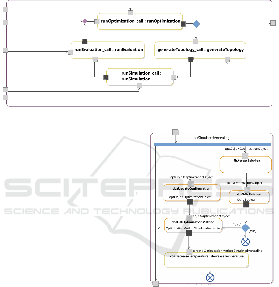
An activity diagram describing the optimization
process is shown in Fig. 6. The runOptimization
call of the callOperationAction is defined as shown
in Fig. 7. The simulated annealing activity diagram
contains several basic elements appearing in most ac-
tivity diagrams: input and output parameters, fork and
decision nodes, CBAs, COAs and flow final nodes. In
addition to the elements shown, the presented EE is
currently able to support join nodes, merge nodes and
activity final nodes.
The activity diagrams expect an object of type
XOptimizationObject that is immediately forked so
that it can be used by all the CallBehaviorActions
optObj : XOptimizationObject
actSAInputPar : XOptimizationObject
actSAOutputPar : XOptimizationObject
Figure 7: Activity diagram of the simulated annealing
method.
requiring it. This class stores the current optimiza-
tion status, such as the best value found so far and
the corresponding configuration. First, it is checked
in the cbaAcceptSolution if the last computed solu-
tion should be accepted or not based on the system’s
temperature. Then, it is checked if the optimization
process should stop, in the case the temperature has
reached the frozen state (cbaSAIsFinished). If not,
the configuration is updated by moving the WDCs
in a pseudo-random manner influenced by the cur-
A Model-Driven fUML Execution Engine for C++
447
rent temperature value (cbaUpdateConfiguration).
This new configuration has to respect some defined
constraints to be valid. As an obvious design choice,
a configuration is considered valid only if all sen-
sor nodes are able to reach at least one WDC by
radio communication. If this is the case, the sys-
tem temperature (stored in the OptimizationMethod-
SimulatedAnnealing class, that contains the proper-
ties related to the optimization method) is decreased
(coaDecreaseTemperature) according to the simu-
lated annealing temperature schedule and the simula-
tion continues.
The described optimization heuristic model has
been completely generated and compiled without
manual changes and executes properly. The obtained
results show that the method follows the expected be-
havior.
4 PERFORMANCE EVALUATION
For evaluating the execution performance, a simple
algorithm has been chosen. Hence, a procedure that
checks if a given number is prime has been imple-
mented. It has been realized in 5 different languages
or models, namely Action Language for Foundational
UML (Alf), fUML (Moka EE), Java, C
++
, and for the
EE exposed in this paper.
Fig. 8 shows the implementation realized in Alf.
The algorithm first checks if the provided number n
is odd. If not, n is clearly not prime. Otherwise,
the number is checked against all the odd possible di-
viders from 3 to b
n
2
c.
The C
++
and Java versions are practically the same,
a c t i v i t y i s P r i m e ( ) {
l e t number : I n t e g e r = 8 1 9 1 ;
l e t d i v i d e r : I n t e g e r = 3 ;
i f ( number % 2 != 0 ) {
do {
i f ( number % d i v i d e r == 0 ) {
W r i t e L i n e ( ” Number n o t p r i me ” ) ;
r e t u r n ;
}
d i v i d e r = d i v i d e r + 2 ;
} w h i l e ( d i v i d e r <= number / 2 ) ;
W r i t e L i n e ( ” Number i s p ri m e ” ) ;
}
e l s e {
W r i t e L i n e ( ” Number n o t p r i me ” ) ;
}
}
Figure 8: Alf code that checks if a defined number is prime.
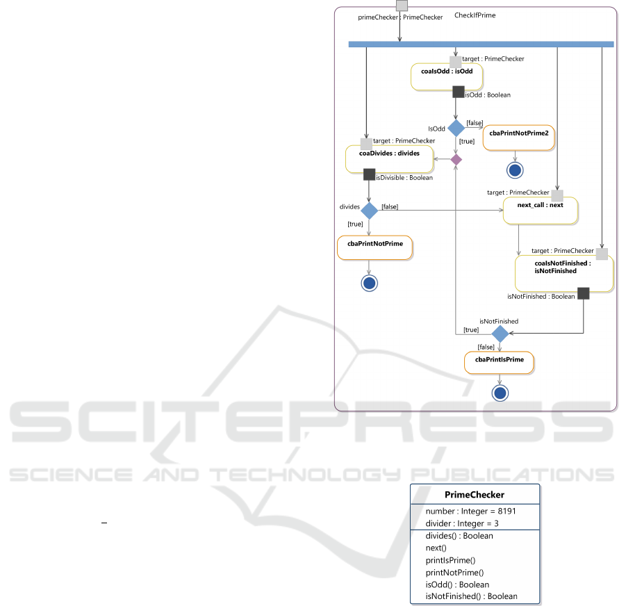
Figure 9: Activity diagram that models a prime checker
composed by 4 COAs (shown in yellow) and 3 CBAs (in
orange) used to print out the results.
Figure 10: Class diagram of the PrimeChecker class.
apart slightly different syntax notations. The fUML
model is realized by the compilation of the Alf code
obtained from the Alf Open Source Reference Imple-
mentation. It is then executed by the Eclipse Moka
fUML EE (Data Access Technologies, 2016).
Regarding the proposed EE, the algorithm has
been modeled as shown in Fig. 9. The activity takes
an instance of a class PrimeChecker as input. This
class has two integer properties (number and divider)
and six operations, as shown in Fig. 10. The class in-
stance will be forked and used as the target of all the
CallOperationActions present in this activity.
Whereas the CallBehaviorActions take care of
MODELSWARD 2017 - 5th International Conference on Model-Driven Engineering and Software Development
448
8191 131071 524287
10
1
10
2
10
3
10
4
10
5
Prime numbers
Execution time (ms)
Alf fUML C
++
EE
Java
C
++
Figure 11: Execution times of the prime checkers.
printing out the result of the evaluation, the Call-
OperationActions perform the operation that ac-
cess or modify the PrimeChecker’s properties.
The prime checker has been tested against
three prime numbers: namely the fifth, sixth and
seventh Mersenne’s primes (M
13
= 8191, M
17
=
131071, M
19
= 524287) (Robinson, 1954).
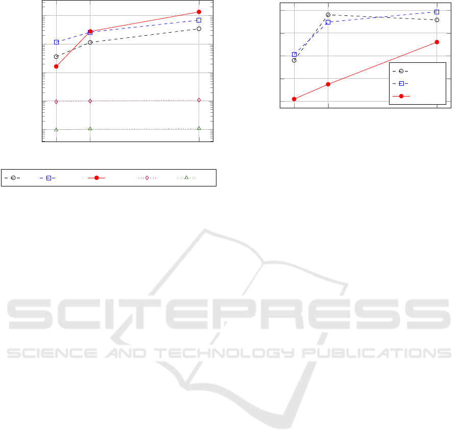
The resulting execution times which are shown in
Table 1 are plotted in Fig. 11. The plotted results are
the arithmetical average of 10 executions performed
on an idle x64 machine with 8GB of RAM. As ex-
pected, the manually implemented C
++
and Java im-
plementation outperform the EEs, by only requiring
less than 100ms in order to execute all the cases.
Among the EEs, the one proposed in this paper is
faster by a factor of 2.2 for the computation of M
13
compared to the Alf EE, and 7 times faster than the
fUML Moka EE. Regarding M
17
, our engine performs
as good as the fUML one, whereas for M
19
it requires
almost double the time of the Moka EE.
The plot shown in Fig. 12 shows the memory peak
of each EE process. Whereas the proposed C
++
EE has
a linear memory occupation, the fUML and Alf EEs
show an inconsistent trend that shows a higher mem-
ory requirement. Our EE memory footprint occupies
for the computation of M
13
18 and 20 times less mem-
ory than the Alf and fUML Moka EEs. As the prime
number increases, this ratio decreases down to a fac-
tor of 1.37.
In Table 2 the storage requirement of the differ-
ent methods are shown. The first column shows the
size in MB of the model (in the fUML case) or the
source code (for Alf) or the compiled binaries (for the
rest). The second one displays the required storage
size for having a runnable standalone version includ-
ing all necessary libraries.
8191 131071 524287
0
200
400
600
800
Prime numbers
Peak memory (MB)
Alf
fUML
C
++
EE
Figure 12: Peak memory usage of the prime checkers.
The table shows that our C
++
implementation has a
significantly smaller storage requirement, actually by
a factor of 5.5 to 6.7 times less than the other EEs and
the Java implementation.
5 CONCLUSIONS
This paper proposed a Model Driven C
++
EE for
fUML. Thanks to it, it has been possible to generate
and execute models in a memory-efficient way. The
UML and fUML complete release libraries currently
have a size of 14.9MB and 2.19MB, respectively,
which is significantly less than already the memory
requirement of the Java virtual machine (∼ 152MB).
With the proposed EE it was possible to model
and execute a heuristic solving a real-life optimization
problem. This XMI model has been used to gener-
ate executable C
++
code that can be directly compiled
without requiring any manual enhancement. The pro-
posed C
++
solution appears to have a constant over-
head that becomes relevant when the number of it-
eration increases. This is probably due to the de-
sign choice of using multiple instead of single inheri-
tance. Because of this, dynamic casts need to be per-
formed in order to obtain access to the elements’ spe-
cific methods, requiring to be executed and checked
at run-time (Goldthwaite, 2006).
The proposed EE, completely realized from the
generation of an ecore model to C
++
code, success-
fully executed the modeled optimization algorithm
and the single components’ unit tests. Thanks to
its easily extensible structure, it is possible to ex-
tend it by adding new components that do not be-
long to the fUML specification without impairing the
reached conformance level. The EE supports the
mainly used activity diagrams’ elements and can han-
dle parameters of any type. The source code can be
downloaded under (Systems and Software Engineer-
ing Group, 2016).
A Model-Driven fUML Execution Engine for C++
449

Table 1: Average execution times and the standard deviation expressed in milliseconds.
alf fUML C
++
EE Java C
++
Prime# Mean σ Mean σ Mean σ Mean σ Mean σ
M
13
3611.6 98.4 11628.1 624.6 1634.8 8.4 94.5 1.7 9.8 2.9
M
17
11381.8 165.2 26097.2 1022.7 27699.7 227.0 99.8 2.2 10.6 1.4
M
19
34357.1 320.4 68925.7 1669.3 134118.8 869.3 108.2 3.2 11.0 1.1
Table 2: Memory requirements for the models and related
libraries in order to execute (in MB).
Storage Requirement
Realized in Program only Incl. Run-time
Alf 0.1 155.1
fUML 0.6 183.1
C++ fUML 1.4 27.2
Java 0.1 152.1
C++ 0.5 0.5
Future Works. For the code to execute, the com-
plete version of the UML and the fUML library is cur-
rently needed. The UML and fUML libraries size is
currently acceptable, but it can be improved. A pos-
sible approach would be to generate a smaller version
of the libraries in order to reduce their memory foot-
print, by including only the elements which are actu-
ally used in the model being generated.
As the workflow has not been integrated into any
IDE yet, the user still needs to perform all single op-
erations separately. However, this can be easily over-
come in the future by integrating all steps into a plugin
for the Eclipse Platform.
REFERENCES
Data Access Technologies, I. M. D. S. (2016). Action lan-
guage for uml (alf) - open source reference implemen-
tation. online.
Goldthwaite, L. (2006). Technical report on C++ perfor-
mance. ISO/IEC PDTR, 18015.
Gosling, J. (2000). The Java language specification.
Addison-Wesley Professional.
Grady, B., James, R., and Ivar, J. (2005). The Unified Mod-
eling Language User Guide. Addison-Wesley, 2nd
edition.
Guermazi, S., Tatibouet, J., Cuccuru, A., Dhouib, S.,
G
´
erard, S., and Seidewitz, E. (2015). Executable mod-
eling with fUML and Alf in Papyrus: Tooling and ex-
periments. strategies, 11:12.
J
¨
ager, S., Jugebloud, T., Maschotta, R., and Zimmermann,
A. (2014). Model based QoS evaluation and valida-
tion for embedded wireless sensor networks. Systems
Journal, IEEE.
This work has been supported by the Federal Ministry
of Economic Affairs and Energy of Germany under grant
FKZ:20K1306D.
J
¨
ager, S., Maschotta, R., Jungebloud, T., Wichmann, A.,
and Zimmermann, A. (2016). An EMF-like UML
Generator for C++. 4th Int. Conf. on Model-Driven
Engineering and Software Development (MODEL-
SWARD 2016).
Kelly, S. and Tolvanen, J.-P. (2008). Domain-specific mod-
eling: enabling full code generation. John Wiley &
Sons.
Kent, S. (2002). Model driven engineering. In Proceedings
of the Third International Conference on Integrated
Formal Methods, IFM ’02, pages 286–298, London,
UK, UK. Springer-Verlag.
Kirkpatrick, S., Vecchi, M. P., et al. (1983). Optimization
by simulated annealing. Science, 220(4598):671–680.
Kleppe, A. G., Warmer, J. B., and Bast, W. (2003). MDA ex-
plained: the model driven architecture: practice and
promise. Addison-Wesley Professional.
Mayerhofer, T. (2012). Testing and debugging UML mod-
els based on fUML. In 34th Int. Conf. on Software
Engineering (ICSE), pages 1579–1582.
ModelDriven.org (2016). Foundational UML (fUML) ref-
erence implementation. online. An open-source im-
plementation of the OMG Foundational Semantics for
Executable UML Models (Foundational UML) speci-
fication.
OMG (2016). fuml 1.2.1 specifications. online.
Robinson, R. M. (1954). Mersenne and fermat numbers.
Proceedings of the American Mathematical Society,
5(5):842–846.
Staines, T. S. (2008). Intuitive mapping of UML 2 activity
diagrams into fundamental modeling concept Petri net
diagrams and colored Petri nets. In 15th IEEE Int.
Conf. and Workshop on the Engineering of Computer
Based Systems (ECBS 2008), pages 191–200. IEEE.
Steinberg, D., Budinsky, F., Paternostro, M., and Merks,
E. (2003). EMF: The Eclipse Modeling Framework.
Addison-Wesley Professional, 2nd edition.
Systems and Software Engineering Group (2016). Model
Driven Engineering for C++ (MDE4CPP). see
http://sse.tu-ilmenau.de/mde4cpp.
Tassey, G. (2002). The economic impacts of inadequate
infrastructure for software testing. National Institute
of Standards and Technology, RTI Project, 7007(011).
Wichmann, A., J
¨
ager, S., Jungebloud, T., Maschotta, R.,
and Zimmermann, A. (2016). Specification and ex-
ecution of system optimization processes with UML
activity diagrams. In 10th Int. IEEE Systems Confer-
ence (SysCon 2016), pages 464–470.
MODELSWARD 2017 - 5th International Conference on Model-Driven Engineering and Software Development
450
