
A Domain-aware Framework for Integrated Model-based System
Analysis and Design
Adrian Rumpold, Reinhard Pröll and Bernhard Bauer
Institute for Software & Systems Engineering, University of Augsburg, Augsburg, Germany
Keywords:
Domain-specific Modeling, Model Transformation, Model-based Analysis.
Abstract:
The increasing complexity of modern embedded systems demands advanced design and development methods.
Incremental evolution of model-based engineering practice has led to heterogeneous tool environments without
proper integration and exchange of design artifacts. These problems are especially prevalent in tightly
regulated domains, where an independent assessment is required for newly developed products, e.g. in
automotive or aviation systems. To address these shortcomings of current engineering practice, we propose a
holistic model-based approach for the seamless design and development of an integrated system model. We
describe an embedding of a variety of domain-specific modeling languages into a common general-purpose
modeling language, in order to facilitate the integration between heterogeneous design artifacts. Based on this
conceptual modeling approach, we introduce a framework for automated model-based analysis of integrated
system models. A case study demonstrates the suitability of this modeling and analysis approach for the design
of a safety-critical embedded system, a hypothetical gas heating burner.
1 INTRODUCTION
Embedded systems have continuously grown in both
hardware and software complexity in recent years,
with the advent of advanced functionality in many
domains, such as automotive, aviation, and industrial
automation.
System designers have attempted to cope with
this increased complexity in two major ways:
First, stricter engineering methodologies have been
applied during the design and implementation
of embedded systems, with a general trend
towards model-based technologies. However,
these model-based approaches have mostly been
limited to the behavior and structure of the system
under development, leaving aside non-functional and
quality aspects.
Second, a very heterogeneous tool landscape
has emerged to conquer the immense variety
of non-functional aspects for such complex
systems – covering legislative and regulatory
issues, performance and timing requirements,
and organizational factors (see chapter 4.1.2 of
Sommerville (2011)).
Due to this asymmetry between partial adoption
of model-based techniques and inconsistent
tooling environments, establishing traceability
and consequent change management have emerged
as two main challenges in systems engineering. The
importance of these fields can be seen clearly in the
context of safety-critical systems, where regulations
require a careful management of development
processes and artifacts with regard to consistent
traceability throughout the product life cycle – for
example the European IEC 61508-1:2010 (2010)
functional safety standard.
The resulting need for careful manual review and
management of traceability and consistency leads to
sub-optimal process efficiency and potential negative
impact on product quality.
Problem Statement
The current state of the art in embedded systems
engineering therefore can be improved through a
more tightly integrated approach to model-based
systems engineering.
Despite some effort towards model exchange
between model-based engineering tools, e.g. through
standardized interchange formats like XMI, seamless
tool integration remains a fundamental challenge.
The resulting need for manual process steps can
lead to postponed quality-related design activities
and consequently reduced overall product quality and
Rumpold A., PrÃ˝ull R. and Bauer B.
A Domain-aware Framework for Integrated Model-based System Analysis and Design.
DOI: 10.5220/0006206301570168
In Proceedings of the 5th International Conference on Model-Driven Engineering and Software Development (MODELSWARD 2017), pages 157-168
ISBN: 978-989-758-210-3
Copyright
c
2017 by SCITEPRESS – Science and Technology Publications, Lda. All rights reserved
157

increased cost of quality defects discovered late in the
development process.
Furthermore, textual artifacts, such as
documentation required for safety certification,
highlight the critical role of consistency between
design models and the textual artifacts generated
from them. Whereas common modeling tools allow
for generation of technical documentation from
system models, the generation of more complex
textual artifacts exceeds their limited capabilities.
In order to overcome the identified weaknesses,
we propose an approach which aims for a tight
integration of all system modeling artifacts and shift
towards (semi-)automated integrated architecture
analyses.
Based on an extensible set of domain-specific
modeling languages, which make up a solid
foundation for a more suitable description of quality
aspects, we aim for a co-evolution of functional
and quality architectures of the system under
development.
Through this strict model-based approach, the
reuse of existing design methodologies is guaranteed,
as long as their results can be formalized using an
underlying metamodel. Consequently, this leads to
a higher level of model consistency and improved
capabilities for impact analysis.
The model-level integration of multiple
domain-specific aspects additionally enables
developers to make use of model-based document
generation, which offers the flexibility mandated by
the development of complex embedded systems.
We foresee that this integrated modeling approach
will lead to increased product and documentation
quality and can thus support the development of
safety-critical and similarly regulated systems.
Outline
Section 2 provides an overview of the fundamental
modeling concepts in our approach and their roles
during integrated system analysis and design. Starting
with general-purpose modeling languages and their
use inside our conceptual framework, we list a set
of essential domain-specific views on the system and
their embedding into the general-purpose language.
Based on this definition of embedded domain-specific
languages, we describe a model-based analysis
framework in Section 3. In Section 4, we demonstrate
the feasibility of our proposed approach using a
realistic use case. There, we perform some exemplary
design and analysis steps regarding the functional
safety of a hypothetical gas heating burner. Section 5
discusses related work regarding the integration
of heterogeneous modeling tools, domain-specific
modeling, and model-based analysis. Section 6
summarizes the key results presented in this paper
and suggests possibilities for future work based on our
current research.
2 A DOMAIN-AWARE APPROACH
FOR SYSTEM MODELING
To overcome the previously identified problems,
we have developed a concept designed to integrate
legacy development and modeling technique with
a new kind of domain-aware modeling approach
and analysis framework. Based on the information
embedded in an integrated system model, textual
artifacts, which had to be maintained manually
before, can now be generated automatically. In order
to switch between these representations and generate
documents, we make use of model-to-model (M2M)
and model-to-text (M2T) transformations.
The high-level concepts and their internal
relationships are illustrated in Figure 1 and will be
elaborated in the following sections.
2.1 General Purpose Modeling
Languages
Following our goal of easy application and seamless
integration into state-of-the-art development
processes, we have decided to embed all relevant
data for the development process within a General
Purpose Modeling Language (GPML), such as UML
or Ecore. The major advantage of this decision is
the reuse of modeling editor capabilities and the
preexisting wide range of general purpose modeling
tools.
These general-purpose languages serve a two-fold
purpose: First, they provide a common modeling
basis for all domain-specific aspect models, as
described in the following section. Second, the
GPML can itself be used to cover certain subsets
of the domain-specific modeling disciplines, if their
expressive power is sufficient for a specific project.
We will see an example for this simplified domain
aspect modeling in the case study in Section 4, where
UML component diagrams and state machines are
used to describe parts of the system architecture.
Our approach does not prescribe a certain GPML
to be used for modeling the integrated system
model. The only necessary requirement is the
possibility to enhance the general-purpose language
with metamodel extensions. In the case of UML
MODELSWARD 2017 - 5th International Conference on Model-Driven Engineering and Software Development
158
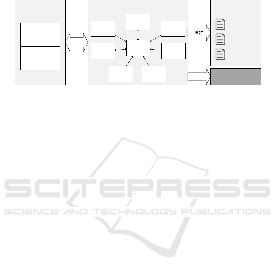
General Purpose
Modeling Languages
Domain-Specific Modeling Languages
...
Purpose-Specific
Documentation
M2M
Timing
Test
(TD)
Integration
(IM)
Security
System
Structure
(SSD)
Safety /
Reliability
(SRD)
Requirements
(REQ)
EMOF/CMOF
Ecore
Safety Cases/
Certification
Documentation
Technical
Documentation
Traceability
Documentation
System
Behaviour
(SBD)
Code Artifacts
(out of scope)
M2T
UML +
Profiles
Figure 1: Conceptual overview of the architecture and analysis framework.
this is achieved by defining profiles that leverage
the stereotype mechanism. Similarly, we can extend
the expressive capabilities of modeling languages
which are themselves specified as UML profiles, for
example SysML. Within the widely popular Eclipse
Modeling Framework (EMF), metamodel extensions
can be easily defined due to the reflexivity of the
Ecore modeling language, which itself is its own
meta-model.
2.2 Domain-specific Modeling
Languages
In order to accurately describe domain-specific
aspects of the system under development, we
embed them into the GPML mentioned above as
domain-specific modeling languages (DSML). Our
approach allows for any number of DSMLs to be used
in conjunction with a general-purpose modeling tool
to obtain an integrated system model (ISM) or Omni
model.
These DSMLs preserve the separation of
concerns, but enable developers to link information
across domains in order to build up a holistic view of
the system under development (SUD) and facilitate
analyses based on domain-specific information.
In this section we briefly introduce some
common domains and their focus, laying the
conceptual groundwork for the following sections that
will provide additional detail and demonstrate the
application of these concepts.
The Requirements Domain (RQD). is related to
the very first engineering tasks of every modern
software development process. As a result of these
tasks, a set of requirements are extracted, which
describe the desired system from a functional as
well as a quality perspective. In order to further
make use of the generated set of requirements,
a certain DSML needs to be defined. Natural
language requirements with additional structuring
capabilities as well as fully machine-processable
requirement models are thinkable. For example a
ReqIF-based DSML (see OMG REQIF v1.2 (2016))
can be used with most common CASE tools. Being
able to reference specific requirements in a model
or parts of them, enables developers to further
use this semi-formal specification of the system
for cross-domain traceability, thus extending the
information base.
The System Structure Domain (SSD). contains
the structural model of the system under development
and reflects the architectural decomposition of the
solution.
Our approach allows for a high degree of
freedom regarding the actual implementation of the
SSD model. For simple projects, the underlying
GPML (see Section 2.1) itself may be sufficiently
expressive to model the system structure without
any domain-specific additions. For more complex
systems, a modeling language with more powerful
abstractions, such as SysML, can be integrated to
describe the structural domain more adequately.
It should be noted that the SSD model may also
be derived from a prior system description in case
of a brown-field project. Here, it is feasible to use
either existing architecture models as a basis for the
newly defined integrated system model, or to reverse
engineer a system description from its code artifacts.
The System Behavior Domain (SBD). contains
modeling artifacts that describe the functional
behavior of the system under development. As
described above for the SSD, a range of modeling
languages can be used to implement the behavioral
model within our approach. Natural choices are the
behavior diagrams found in the Unified Modeling
A Domain-aware Framework for Integrated Model-based System Analysis and Design
159

Language or its SysML extension.
However, different domain-specific modeling
languages might be more familiar to designers
of certain embedded systems; one example is
the Function Block Diagram (FBD) notation for
programmable logic controllers defined in the
IEC 61131-3 and IEC 61499 international standards.
Given a suitable technology integration bridge
(e.g. OSLC or ModelBus, see also Section 6),
it is conceivable to integrate behavioral models
from widely used simulation tools like Simulink
or Stateflow, as an intermediate step while
re-engineering legacy systems.
The Safety and Reliability Domain (SRD). covers
the modeling and analysis of system reliability.
Such analyses are invaluable and often mandated by
regulations, e.g. in the development of safety-critical
systems, to demonstrate the system’s expected failure
behavior and obtain measures of reliability and
availability.
In order to quantify the reliability of a system,
a thorough analysis of potential hazards and
their associated risks is required. These hazard
analyses require profound domain knowledge and are
frequently performed as team efforts. Despite the
interactive nature of these activities, their results can
be formalized in the form of a hazard model that
describes identified hazards and the risks as well
as possible faults and failures that can cause these
hazardous events.
A major task in the design of safety-critical
systems is the classification of hazards based on their
associated risk. Risks that are deemed intolerable,
either by societal or regulatory standards, have to be
mitigated by targeted risk reduction measures. Based
on the necessary level of risk reduction, levels of
safety integrity and associated safety requirements
can be allocated to protective system components.
This SIL allocation process requires the quantitative
analysis of failure occurrence likelihoods.
Traditionally, such quantitative reliability models
are maintained in separate tool environments,
decoupled from the actual system model. This setup
can lead to inconsistencies in reliability models and
decisions made based on them, when proper care is
not taken during ongoing development of the system.
However, many common of the traditional reliability
modeling approaches can easily be adapted for use in
model-based environments. For example, the widely
used Fault Tree Analysis (FTA) technique defines a
set of graphical model elements to analyze failure
causes in a system Vesely et al. (1981), and proves
a suitable candidate for a domain-specific modeling
language with a familiar graphical representation.
By embedding the reliability and hazard analysis
models into the integrated system model, our
approach allows to easily maintain full traceability
between these models and their associated system
model counterparts in the SSD and SBD. Moreover,
change impact analyses can be easily performed
based on this traceability information, whenever a
modification to any part of the system model is made.
In the context of model-based systems
engineering, it makes sense to move beyond
the traditional FTA technique and incorporate a
component-based extension, such as the Component
Fault Trees as proposed in Kaiser et al. (2003). This
hierarchical structuring of reliability information
creates synergies with the end-to-end traceability
provided by our modeling approach.
The Test Domain (TD). reflects the information
specific to the tester’s view on the system under
development. It can be used to formalize artifacts
related to quality assurance activities, such as test
plans, test cases, and test execution reports.
However, the true strength of the test domain
model lies in the integrated support for model-based
testing approaches. Depending on the expressiveness
of the modeling languages used for the system
description in the SSD and SBD, the test domain
can be simply seen as an extension of these
domains. However, it is also conceivable to embed
model languages specific to the testing domain,
such as the OMG-maintained UML Testing Profile,
which provides modeling facilities for test behavior
description as well as quality assurance management
activities.
The Integration Model (IM). as illustrated in
Figure 1, marks the central model artifact in order
to establish a mechanism for domain-specific model
linking and mapping of artifacts. The cross-domain
linking, represented by the bidirectional connectors,
on the one hand enables developers to make use of
a solid and consistent tracing mechanism applicable
throughout all development artifacts. On the
other hand the IM is meant to provide additional
information to the test engineer, previously out of
scope. Therefore, distinct elements of the system
model are mapped via the IM to concepts used in the
test model. This also holds for other combinations
of domain-specific model data. Note, that the IM
does not model any information that has already been
modeled in a connected domain. It only holds a
subset of the resulting data generated by analyses
performed on linked domains and establishes the
MODELSWARD 2017 - 5th International Conference on Model-Driven Engineering and Software Development
160

connections between its model artifacts. A necessary
precondition for the seamless integration of all
connected information domains is a common M3
metamodel definition for the tracing specific DSL
parts.
Other Domains. The above modeling domains
cover a wide range of engineering artifacts relevant
during the design and construction of embedded
and/or safety-critical systems. However, our
modeling approach does not prescribe a fixed set
of domain-specific modeling languages and domains
and can easily be extended and tailored to each
specific modeling use case.
The set of modeling domains presented above
are relevant to the design of embedded systems
in particular. However, our framework may also
take into account aspects of business and other
applications. To this end we envision domains
addressing security and privacy considerations
(e.g. to model information flows), timing models,
description of data persistence, as well as usability
models.
2.3 Purpose-specific Documentation
While the domain-specific models described
above are derived from the GPML model through
model-to-model transformations, our approach also
covers the generation of purpose-specific textual
artifacts through model-to-text transformations.
The automated generation of textual
documentation is an important step towards more
tightly integrated system engineering processes and
plays a crucial role in the quality-driven architecture.
The continuous and early design-time availability of
textual design artifacts can support the subsequent
fulfillment of process requirements.
The holistic nature of our proposed integrated
system modeling approach facilitates document
generation on a high abstraction level. For example, a
common documentation requirement in safety-critical
systems calls for seamless forward and backward
traceability from system requirements down to the
implementation level and its proper documentation.
Since the Omni model contains all necessary
architectural elements and their relationships,
generating such documentation consistently and in an
easily navigable format (for example as hyperlinked
HTML documents) is an effortless automated task.
The use of hypertext formats is superior to
traditional documentation formats for results of
preliminary risk and hazard assessments. Current
documentation artifacts used for the certification
of safety-critical systems commonly relies on
spreadsheets and static PDF documents for this
purpose. Using hypertext formats elegantly solves the
problem of limited traceability of these documents.
Since an HTML document allows to directly place
links between the results of these assessments, their
associated model elements, and related documents.
This improvement allows easier familiarization with
the system and better comprehension both as system
documentation and for certification purposes.
Similarly, more formal certification artifacts can
be generated from the integrated system model:
The Goal Structuring Notation (GSN) is a graphical
notation for representation of structured arguments,
as in the case of safety or assurance cases for
safety-critical systems Kelly and Weaver (2004).
Hereby, the purpose of a formal argument notation
is to tie claims about the safety of the system under
development together with supporting evidence.
Here, our approach can be used to generate a coherent
set of safety documentation following the structured
argument of a given GSN model based on the entire
set of domain-specific models and analysis results
contained in the integrated system model.
The availability of usable, consistent, and
up-to-date textual artifacts can help to reduce cost
of safety certification by supporting high quality and
early review of certification-related documents.
Additionally, the same model-based document
generation approach can be used to capture the
results domain-specific analyses of the system that
cover individual stakeholders’ interests. From a
project management standpoint, we envision this
approach to be useful for analyzing certain Key
Performance Indicators of the system, for example
test and requirement coverage metrics as an indicator
of overall project progress.
2.4 Code Generation
While out of the direct scope of our research, it should
be noted that the final integrated system model is
a suitable basis for generation of source code, as
indicated by the second model-to-text transformation
step in Figure 1. The integrated nature of the Omni
model allows the code generation engine to make
more educated decisions about the context of the
source code to be synthesized. A possible scenario
could be the automated application of defensive
programming techniques in generated code, e.g.
pre- and post-conditions or checksums, based on
component contracts or safety requirements from the
integrated system model.
A Domain-aware Framework for Integrated Model-based System Analysis and Design
161

3 MODEL-BASED
ARCHITECTURE AND
ANALYSIS FRAMEWORK
Based on the modeling approaches introduced in the
previous section, we have developed a technology
demonstrator geared towards the domain-aware
modeling of safety-critical systems and their quality
attributes. In addition to the domain-specific
metamodels, the prototype includes a framework for
definition of domain-specific architecture analyses,
introduced below in Section 3.2.
3.1 Technical Background
As shown in Figure 2, the analysis framework consists
of three major components:
• Enterprise Architect as a general purpose
modeling tool, used to provide the user interface
for the system designer (Section 3.1.1)
• A relational database system for persistent storage
of the model repository (Section 3.1.2)
• The actual architecture and analysis framework,
which offers model analysis services via a web
service interface (Section 3.1.3)
3.1.1 Domain-specific Modeling in General
Purpose Modeling Tool
The commercially available modeling and design
platform Enterprise Architect (EA) by Sparx
Systems serves a the central modeling tool for our
demonstrator. As a general purpose modeling tool,
it fully supports the UML 2.5 specification and
includes an extension mechanism (dubbed MDG
Technologies) as an implementation of UML profiles
for use inside the EA modeling environment.
These MDG technology specifications can extend
existing UML metaclasses as stereotypes with new
attributes and define custom visual representations
for use of these stereotypes in diagrams. We have
developed custom MDG technologies for each of
the domain-specific metamodels introduced in the
previous section, to create the necessary modeling
vocabulary to the system designer.
3.1.2 Shared Model Repository Access
In its current form, the analysis server accesses the
integrated system model through a relational database
which is configured as the model repository inside
Enterprise Architect. A custom-built object-relational
mapper (EAORM) provides programmatic access to
the model repository and allows for its consistent
modification. As described in Section 6, in the
future we aim to replace this rather tight coupling
between the tools by means of a model-oriented
interoperability platform, such as ModelBus.
3.1.3 Analysis Framework Integration
In order to anticipate a wider range of modeling tools,
our analysis framework has been implemented as a
stand-alone component outside the general purpose
modeling environment. The functionality of the
framework core is exposed through a graphical user
interface for rapid feedback during development of
model analysis, and a server component for remote
access to the analysis functionality.
It provides a RESTful web service interface to
the model analysis and textual artifact generation
functionality. Communication between EA and
the analysis framework is brokered by a thin web
service client implemented as a custom plug-in inside
Enterprise Architect.
It should be noted that no model representation
is exchanged via the web service interface. Instead,
both tools share access to a common model repository
(see below), enabling them to refer to model elements
solely by their identifiers. This approach allows the
analysis framework to access a native representation
of the entire integrated system model. While a generic
model interchange format like XMI might satisfy the
requirements for unidirectional exchange of model
data between tools, problems arise in scenarios where
bidirectional access is required. In order to keep the
model consistent, the analysis framework needs to be
able to persist the results of its analyses in the same
model as its input data, therefore bidirectional access
to the model is essential.
The clear architectural separation between
modeling and analysis functionality facilitates
another important use case: The analysis framework
can be used independently from the design tool, for
example as part of a continuous integration pipeline.
Since all functionality of the framework is offered
through a programmatic interface, the only necessary
addition is a machine-readable description of the
analyses to be executed. Such descriptions can even
be stored as part of the integrated system model,
creating a truly self-contained system model that
spans the entire product lifecycle.
We have chosen the Operational QVT language
(QVTo for short, see OMG QVT v1.3 (2016);
Kurtev (2007) for details) as the model-to-model
transformation language for our prototype. Each
domain-specific model can be obtained from the
integrated system model by applying its associated
MODELSWARD 2017 - 5th International Conference on Model-Driven Engineering and Software Development
162
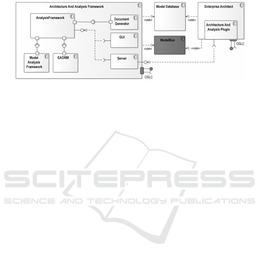
Figure 2: Technical overview of the reference technology platform architecture. Components shaded in dark gray refer to
future extension possibilities, as described in Section 6.
transformation that maps the extended general
purpose modeling language (see Section 2.1) onto the
domain-specific modeling languages (Section 2.2).
In order to simplify the integration with the
Eclipse EMF-based QVTo implementation used, all
domain-specific models have been implemented as
Ecore metamodels.
Model analyses can define dependencies on the
domain models necessary for their execution. The
transformation engine in the analysis framework
automatically determines the appropriate M2M
transformations to be applied to the integrated system
model when performing a model analysis.
3.1.4 Model-to-text Transformation
Since our prototype is focused on document
generation as HTML pages, a general purpose
templating language (Jtwig) was used for
model-to-text transformation instead of a more
formal M2T language. However, depending on the
exact nature of the output format, M2T languages
such as Eclipse Xtend or Xtext might provide more
appropriate expressive capabilities – especially if
the resulting textual artifacts should be expressed
in a domain-specific language or integrated with an
existing tool chain.
Code generation from the system model was
beyond the scope of our developed prototype. For the
purpose of our study, generation of C code from the
integrated system model was delegated to an existing
embedded systems engineering toolchain, that was
adapted to make use of the additional domain-specific
information contained in the Omni model.
3.2 Model-based Analyses
As part of the framework prototype, we have
developed a range of model analyses, that can
be applied to the integrated system model and its
constituent domain-specific models.
Conceptually, we have identified three major
classes of model analyses, that can be distinguished
by their types of input and output models:
Validation Analyses. consume one or multiple
input domain-specific models, but do not generate
any new model elements as their output. Rather, a
validation analysis verifies the syntactic and semantic
well-formedness of its input models. In case this
validation fails, the analysis produces a report of
the identified violations and returns it as a separate
analysis result to the client.
Therefore, the purpose of validation analyses is
the assurance of model integrity and quality. They
are feasible candidates for tighter integration with
the modeling environment, and can be executed
continuously without user interaction to provide rapid
feedback to the designer about the state and quality of
the model being modified.
Note, that the existence of this class of
analyses is a testament to the state of metamodel
extensibility in current general-purpose modeling
tools. Schleicher and Westfechtel have already
highlighted this shortcoming in their 2001 paper
and identified it as the primary driver for so-called
descriptive stereotypes. If GPML tools provided
first-class support for restrictive stereotypes or even
full restrictive metamodel extensions instead, the
syntactic and semantic constraints for a DSML
could be directly validated as part of the metamodel
extension.
Calculation Analyses. consume one or more input
domain-specific models and calculate additional
attributes for existing model elements, but do not add
new elements.
A Domain-aware Framework for Integrated Model-based System Analysis and Design
163
These analyses can be seen as the formalization
of a function application to their input models.
Examples for this class of analysis are numerous, e.g.
the automated update of probability information in
reliability models, risk classification, or the analysis
of timing bounds in behavioral models.
In our analysis framework, calculation analyses
are an obvious application point for the Model
Analysis Framework (MAF) described by Saad and
Bauer (2013), which uses an application of data-flow
analysis techniques originally introduced in compiler
construction.
Generative Analyses. both consume and produce
model elements in one or more domain-specific
metamodels. As such, they are similar to
model-to-model transformations, however, their
purpose is more broad, so that they should be
considered as a separate entity. Additionally, by
implementing this type of transformation as an
analysis inside our framework, they share a common
interface with the remaining classes of analyses,
helping to reduce complexity for the client.
Depending on their respective purpose, we
can further distinguish endogenous and exogenous
generative analyses, similar to the distinction found
in the model transformation world.
Possible uses of this class of analyses are very
broad: One possible example is the support of the
system designer through wizard-type functionality,
for example to generate skeleton reliability models
from an existing structural model of a system.
A different application scenario is the automated
creation of a test model and test cases from
the abstract description of system structure and
functionality in the integration model.
Lastly, generative analyses can be used as the
entry point for model-to-text transformations. They
can be used to provide a consistent interface to make
the creation of textual artifacts transparent to the
client, hiding the added complexity of the actual
invocation of the M2T transformation engine.
Analyses in our framework can be chained
together to form more complex analysis scenarios.
In order to guarantee consistency, analyses can
declare execution order constraints. The analysis
framework then determines an appropriate ordering
of eligible analyses, performs the necessary M2M
transformations, and then executes the actual analysis
code.
4 CASE STUDY: RELIABILITY
MODEL FOR A GAS HEATING
BOILER
In the following section we will demonstrate the
use of our domain-specific modeling approach to the
reliability analysis of a gas heating boiler. Such
boilers are commonly found in residential buildings
to provide central heating by combustion of natural
gas in a burner. The natural gas used in such a heating
is highly flammable. Therefore, the design of such a
system must include an evaluation of the safety risks
and reliability of its protection systems, to minimize
the risk of personal injury arising from a malfunction.
Due to the limited space in this paper, the artifacts
shown in this case study represent only a small subset
of the overall system model. However, they nicely
illustrate the application of our integrated modeling
approach and its suitability for the development of
safety-critical systems.
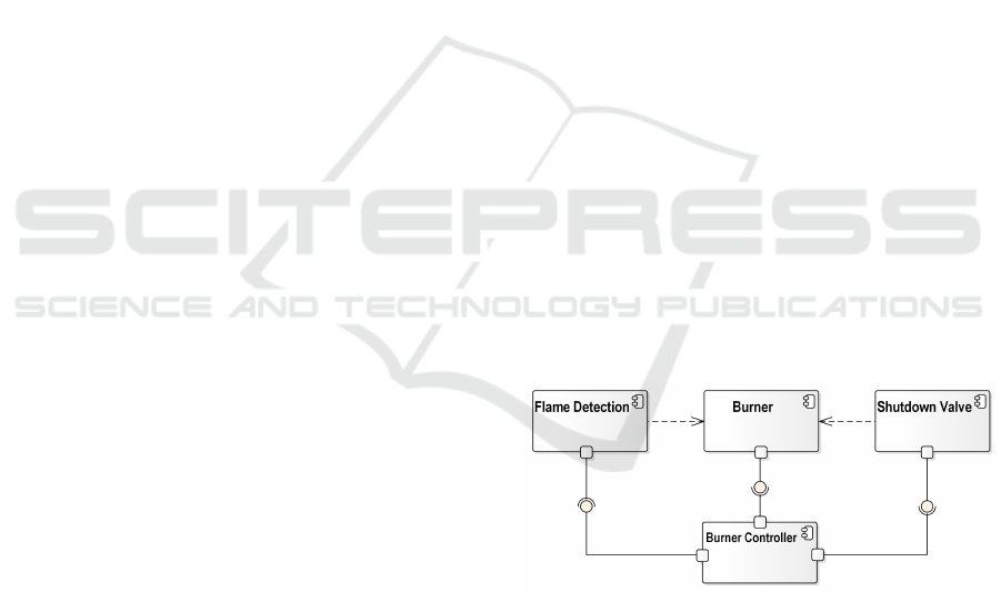
4.1 System Structure and Behavior
Since we are describing the system architecture
on a very abstract level, a plain UML component
diagram provides appropriate expressive capabilities
to describe the system structural domain for this
case study. Figure 3 gives a high-level architecture
overview for the gas heating boiler of our example
system. Such a model can be derived at early design
stages, as soon as the operational context of the
systems has been determined.
Figure 3: Architecture of the gas heating system.
We use UML state machines to model the
behavior of the burner controller, which monitors
and controls the combustion of natural gas inside
the burner. As an example, Figure 4 describes the
main operating states of the burner controller, which
can be either operational or shut down in case a
malfunction of the flame supervision mechanism has
been detected.
MODELSWARD 2017 - 5th International Conference on Model-Driven Engineering and Software Development
164
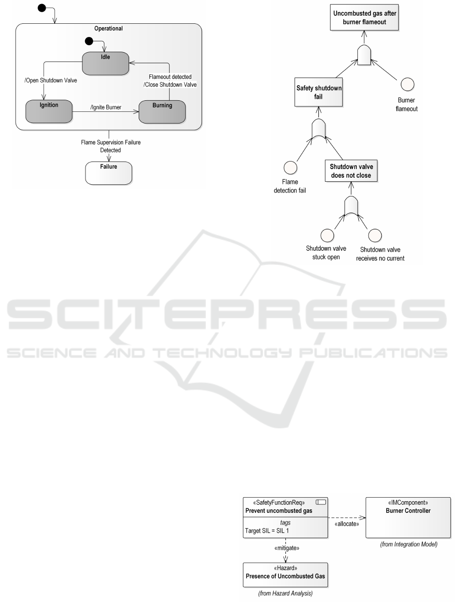
Figure 4: Behavior model of the burner control logic.
4.2 Reliability Model
An early step during development of a safety-critical
system is the assessment of potential hazards and risk
associated with the system under development (see
section 7.4 of IEC 61508-1:2010 (2010) for details).
This hazard and risk assessment, performed by a
team of domain experts, can be documented in a risk
assessment model.
Based on this initial assessment, mitigation
measures are defined for safety-relevant hazards to
determine the necessary risk reduction to achieve a
tolerable risk. A Fault Tree Analysis (FTA) can
be carried out to quantitatively determine the actual
likelihood for a given hazard based on the hazard
assessment and the proposed levels of protection.
As an illustrative example, we have chosen to
analyze a potentially hazardous failure of the heating
system, namely the presence of uncombusted gas
in the burner chamber following a flameout. This
situation can lead to rupture of the heating vessel
due to over-pressurization or rapid deflagration or
explosion of the uncombusted gas in the presence of
an igniting spark. Both hazards are assumed to occur
with an intolerably high likelihood, which prompts
the addition of a flame detection mechanism and
an automatic safety shutdown valve to the heating
system.
Figure 5 shows the fault tree model for this
hazardous event, highlighting the two components
of the analysis: the root causes for the hazardous
event, and the simultaneous failure of protective
safety functions. Note that all basic events can be
further developed – the fault tree has been truncated
to fit the scope of the use case.
Figure 5: Fault tree model for hazardous event
Uncombusted Gas after Burner Flameout.
4.3 Requirements Model
Based on an annotation of the acceptable risk
target for the hazardous event in the model and
the occurrence likelihood of the root causes for the
flameout (calculated through an architecture analyis),
our framework can identify necessary safety function
and allocate safety integrity levels to them (see
sections 7.5 and 7.6 of IEC 61508-1:2010 (2010) for
the regulatory background).
Figure 6 shows a part of the safety requirements
model for the previously discussed risk of
uncombusted gas. A safety function with a specified
safety integrity level is required to mitigate this risk,
and is allocated to a system component, namely the
burner controller.
Figure 6: Safety requirements model.
A Domain-aware Framework for Integrated Model-based System Analysis and Design
165
Note, that besides this domain-specific model of
safety requirements, a complete integrated system
model of the gas heating would also contain all
functional requirements that govern the regular
operation of the system.
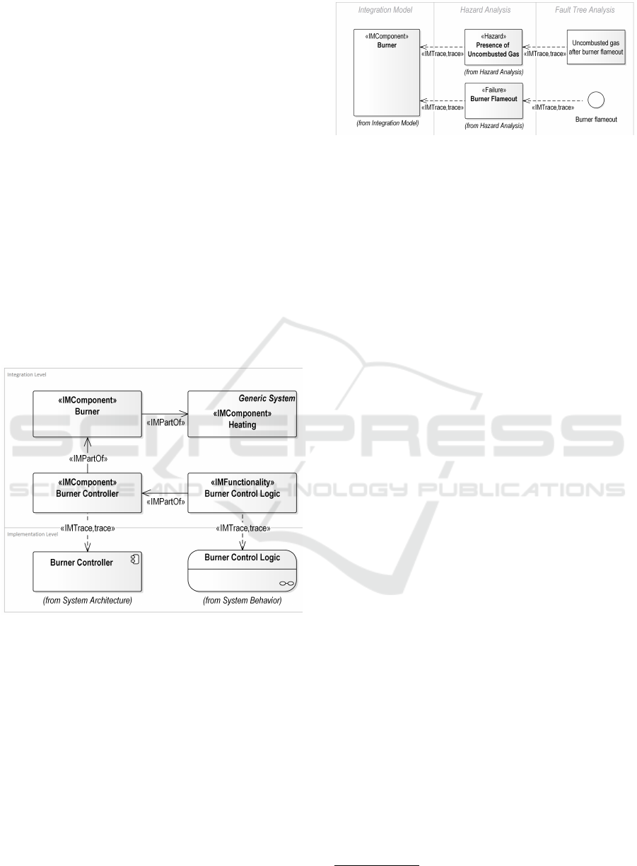
4.4 Integration Model
The integration model for our use case ties together
the system structure and behavioral domain, with
all additional domain-specific models regarding the
reliability of the heating system.
We can see from Figure 7 that the integration
model forms a hierarchy of abstract components
with the entire system under development at its root.
Furthermore, the IM reflects the allocation of abstract
functionality, e.g. the logic of the burner controller, to
components and contains traceability information into
the concrete behavioral model. In our example, the
integration model associates the state machine for the
burner control (see Figure 4) with the abstract control
logic functionality.
Figure 7: Excerpt from Integration Model with links to SSD
and SBD.
Beyond this abstract description of the system
behavior and structure, the integration model plays
a crucial role for maintaining the consistency of
the reliability model. By establishing a link
between identified hazards, failure events in fault
tree models, and the associated system components
(as seen in Figure 8), the IM forms the basis
for the integrated consideration of reliability and
risk management activities during the design of
the heating system. Based on this information,
accompanying documentation can be generated to be
used as evidence in safety certification of the burner
control system.
Figure 8: Excerpt from Integration Model with links for
reliability model.
5 RELATED WORK
Our work relates to previous research in three
related, but separate fields: Firstly, our approach
provides a means of integrating various engineering
disciplines into a coherent tool environment.
Each of these disciplines brings with it its own
set of domain-specific engineering artifacts and
modeling languages. Finally, our implementation
of an architecture analysis framework based on an
integrated system model relates to prior work in the
field of model-based analysis.
The following sections give a short overview of
the relevant literature in these three fields, as they
related to our current research.
5.1 Modeling Tool Integration
In his seminal work, Wasserman (1990) describes
an approach for integration of heterogeneous tools
in a software engineering tool chain. He describes
an integrated software engineering framework based
on three cardinal dimensions of interoperability –
presentation, data, and platform integration.
The EU-funded iFEST project (Industrial
Framework for Embedded Systems Tools
1
) was
aimed at developing an integrated framework for
embedded systems, addressing both software and
hardware concerns. The iFEST approach specifies
a tool integration framework that leverages the
OSLC specification to allow data exchange between
heterogeneous modeling tools. Since it is focused
exclusively on the aspect of tool integration, this
approach does not address the field of model-based
analyses of the integrated system model.
5.2 Domain-specific Modeling
Zschaler et al. (2009) proposes a generalization of
DSLs to domain-specific modeling languages, in
1
http://www.artemis-ifest.eu/
MODELSWARD 2017 - 5th International Conference on Model-Driven Engineering and Software Development
166

order to capture common concepts found in families
of related DSLs and facilitate automation.
Similarly, de Lara et al. (2015) describe
an approach for domain-specific multi-level
metamodeling languages, allowing for the definition
of deep language hierarchies. Their approach
contains a set of reusable metamodel transformations
for management of multi-level metamodeling
languages and describes approaches for code
generation in such a setting.
The use of UML as a graphical visualization
language for domain-specific modeling languages
is proposed by Graaf and van Deursen (2007).
Their work proposes model-to-model transformations
as a means of deriving a visual representation
from a domain-specific model. Conceptually, these
transformations can be regarded as an embedding of
the DSML into a generic-purpose modeling language,
namely into UML.
5.3 Model-based Analysis
Papadopoulos and McDermid (1999) introduce
HiP-HOPS (Hierarchically Performed Hazard
Origin and Propagation Studies), a methodology
for model-based hierarchical reliability analysis
of component-based systems. Based on the
architecture of the system under analysis and
certain failure annotations, HiP-HOPS allows for
bottom-up generation of Fault Trees and so-called
interface-focused FMEA results for a system.
Under the HiP-HOPS methodology, components are
augmented with additional model information about
their failure behavior. Various classes of interface
failures are defined, that can be used to describe the
black-box failure model of a system on a component
level.
This approach has subsequently been extended
to accommodate aspects of automatic architecture
optimization. Papadopoulos et al. (2010) describes
a conceptual approach for the automatic allocation of
safety integrity levels to components of safety-critical
systems. This work is focused on the automotive
domain and uses the EAST-ADL2 modeling language
for architecture description. Similarly, Papadopoulos
et al. (2011) proposes a more generic architecture
optimization approach based on the HiP-HOPS
methodology and the use of genetic algorithms.
A complementary approach can be found in the
EU-funded MBAT project (Combined Model-based
Analysis and Testing of Embedded Systems
2
).
This project aimed to provide a methodology and
technology platform for specification of system
2
http://www.mbat-artemis.eu/
analysis and V&V activities in the context of
embedded system engineering. The central element
of the proposed methodology is the so-called A&T
model (short for [static] analysis and [model-based]
testing), highlighting the focus of the approach to the
quality-assurance domain.
6 CONCLUSIONS
We have proposed a valuable approach for integrated
system modeling and model-based architecture
analysis.
Our work introduces a solution to the challenge of
integrating both system modeling and quality-related
artifacts in the design and implementation of
embedded systems. The resulting integrated system
model or Omni model establishes explicit traceability
between domain-specific modeling artifacts and
enables consistent change management and change
impact analyses.
Based on this holistic, model-based view
on the entire system under development,
purpose-specific textual artifacts can be generated in
an automated fashion through the use of model-to-text
transformations.
We have developed a reference technology
platform that combines this integrated system
modeling approach with a model-based analysis
framework. The suitability of this prototype is
demonstrated through a case study, which illustrates
the use of the framework to model the reliability
aspects of a residential gas heating burner, a simple
safety-critical embedded system.
Future Work
While our technology prototype has shown the
feasibility of our theoretical approach, we see several
possible fields for improvement and extension of the
architecture and analysis framework:
In order to reduce the need for re-creation of
existing domain-specific modeling artifacts inside a
general-purpose modeling tool, existing modeling
tools can be integrated by means of a technology
integration bridge. OSLC
3
(Open Services for
Lifecycle Collaboration) and ModelBus
4
are two
suitable candidates for such an integration platform.
Both aim to provide heterogeneous tool integration
through open, web-based technologies and could be
used to establish transparent traceability between our
3
http://www.open-services.net
4
http://www.modelbus.org
A Domain-aware Framework for Integrated Model-based System Analysis and Design
167

proposed integration model and models distributed
across one or more domain-specific tools. Figure 2
illustrates the addition of OSLC and/or ModelBus
to our reference technology platform as part of the
model-based analysis framework.
A similar argument can be made for a more
generic access to a shared model repository.
Currently, our prototype shares a relational database
for the integrated system model with the proprietary
Enterprise Architect model repository. ModelBus,
with its integrated model repository component (see
Hein et al. (2009), section 2), can help to reduce this
tight coupling between the generic persistence layer
and a single modeling tool.
Besides the technical improvements, we foresee a
worthwhile extension of our modeling approach with
aspects of contract-based design. Since our integrated
system model already encompasses comprehensive
information about non-functional aspects of the
system under development, this knowledge can
be used to derive constraints and guarantees for
system components. The automated nature of our
analysis framework allows for design optimization
based on domain-specific models. Information about
component prerequisites and guarantees in the form
of contracts can be used to reduce the complexity of
the design space during such automatic architecture
optimization.
ACKNOWLEDGEMENTS
The research in this paper was funded by the
German Federal Ministry for Economic Affairs and
Energy under the Central Innovation Program for
SMEs (ZIM), grant numbers KF 2751303LT4 and
16KN044120.
REFERENCES
de Lara, J., Guerra, E., and Cuadrado, J. S. (2015).
Model-driven engineering with domain-specific
meta-modelling languages. Software & Systems
Modeling, 14(1):429–459.
Graaf, B. and van Deursen, A. (2007). Visualisation
of domain-specific modelling languages using uml.
In 14th Annual IEEE International Conference and
Workshops on the Engineering of Computer-Based
Systems (ECBS’07), pages 586–595. IEEE.
Hein, C., Ritter, T., and Wagner, M. (2009). Model-driven
tool integration with modelbus. In Workshop Future
Trends of Model-Driven Development, pages 50–52.
IEC 61508-1:2010 (2010). Functional safety of
electrical/electronic/programmable electronic
safety-related systems - Part 1: General requirements.
Standard, International Electrotechnical Commission,
Geneva, CH.
Kaiser, B., Liggesmeyer, P., and Mäckel, O. (2003). A new
component concept for fault trees. In Proceedings of
the 8th Australian workshop on Safety critical systems
and software-Volume 33, pages 37–46. Australian
Computer Society, Inc.
Kelly, T. and Weaver, R. (2004). The Goal Structuring
Notation–A Safety Argument Notation. In Proc. of
Dependable Systems and Networks 2004 Workshop on
Assurance Cases.
Kurtev, I. (2007). State of the art of QVT: A
model transformation language standard. In
International Symposium on Applications of Graph
Transformations with Industrial Relevance, pages
377–393. Springer.
OMG QVT v1.3 (2016). Meta Object Facility (MOF) 2.0
Query/View/Transformation Specification, Version
1.3. Specification, Object Management Group
(OMG), Needham, MA.
OMG REQIF v1.2 (2016). Requirements Interchange
Format (ReqIF), Version 1.2. Specification, Object
Management Group (OMG), Needham, MA.
Papadopoulos, Y. et al. (2010). Automatic allocation
of safety integrity levels. In Proceedings of the
1st workshop on critical automotive applications:
robustness & safety, pages 7–10. ACM.
Papadopoulos, Y. et al. (2011). Engineering failure analysis
and design optimisation with HiP-HOPS. Engineering
Failure Analysis, 18(2):590–608.
Papadopoulos, Y. and McDermid, J. A. (1999).
Hierarchically performed hazard origin and
propagation studies. In International Conference
on Computer Safety, Reliability, and Security, pages
139–152. Springer.
Saad, C. and Bauer, B. (2013). Data-Flow Based
Model Analysis and Its Applications, pages 707–723.
Springer Berlin Heidelberg, Berlin, Heidelberg.
Schleicher, A. and Westfechtel, B. (2001). Beyond
stereotyping: Metamodeling approaches for the
UML. In Proceedings of the 34th Annual Hawaii
International Conference on System Sciences, page 10
pp. IEEE.
Sommerville, I. (2011). Software Engineering. Pearson
Education, 9th edition.
Vesely, W. E., Goldberg, F. F., Roberts, N. H., and Haasl,
D. F. (1981). Fault tree handbook. Technical report,
DTIC Document.
Wasserman, A. I. (1990). Tool integration in software
engineering environments. In Software Engineering
Environments, pages 137–149. Springer.
Zschaler, S., Kolovos, D. S., Drivalos, N., Paige, R. F., and
Rashid, A. (2009). Domain-specific metamodelling
languages for software language engineering. In
International Conference on Software Language
Engineering, pages 334–353. Springer.
MODELSWARD 2017 - 5th International Conference on Model-Driven Engineering and Software Development
168
