
A UML Profile for the Specification of System Architecture Variants
Supporting Design Space Exploration and Optimization
Alexander Wichmann, Ralph Maschotta, Francesco Bedini, Sven J
¨
ager and Armin Zimmermann
Systems and Software Engineering Group, Technische Universit
¨
at Ilmenau, Ilmenau, Germany
Keywords:
System Modeling, Architecture Variant Description, UML Profile, Design Space.
Abstract:
The optimization of complex systems as well as other design methods require a description of the system
parameters, or the design space. Explicit encoding of all possible variants is practically impossible, thus an
implicit method is needed. While this is easy for purely numerical parameters and a fixed number of them as
usually assumed in direct or indirect optimization, it is quite hard for systems in which the architecture and thus
the structure of the parameters themselves can be varied. This paper introduces an approach to specify system
architecture variants in a concise way and proposes a UML profile for this task. Standard UML meta model
elements are used for the description of variant-specific stereotypes. An example of a variant specification for
a communication network model is presented.
1 INTRODUCTION
Model-based systems engineering is helpful in allow-
ing early validation of complex system designs and
reduction of costly failure corrections in late develop-
ment states. The underlying models have to capture
all significant information, which often contains both
(static) structural as well as (dynamic) behavioral as-
pects. Numerous design decisions must be made to
obtain a hopefully close-to-optimal system. These de-
cisions could be supported or automated by a closed-
loop indirect optimization approach (van Leeuwen
et al., 2014), in cases where the descriptional power
of linear programming is insufficient. The set of valid
system variants (or design alternatives), also called
the design space (Taghavi and Pimentel, 2010), has
to be specified as an input to the optimization heuris-
tic. Such a specification (not its derivation or explo-
ration, though) is comparably simple as long as all
parameters are just numerically valued with a given
interval. In fact, it is usually described by a vec-
tor of n real values for a system with n design pa-
rameters, and we may imagine the design space as
an n-dimensional geometrical space then. However,
this paper addresses the problem of architecture opti-
mization, in which the structure of variants and design
parameters is typically much more complex, and in
which already the number of parameters n is not ob-
vious as it depends on other design parameter value
choices: Components may be optional and include a
variable attribute. If such an optional component is
not used inside a system variant, then their properties
as well as the corresponding parameters are also not
existing. Thus, the well-understood research area of
linear systems with numerical parameters cannot be
applied here.
What should be described for the design space
about a variable architecture? First of all, the gen-
eral structure must be defined including system com-
ponents as well as their properties and relations to
other components. Furthermore, variants of the sys-
tem model have to be specified in order to solve the
following questions: How many instances of com-
ponents are existing? How many instances belong
to or comprise another one? What are the limits of
the numbers of instances? Which values can be as-
signed to component properties? Which interface re-
alization should be used? Should an optional fea-
ture be used? What are fixed components and at-
tributes? How should an attribute be specified, which
depends on another attribute? What kind of connec-
tions should be used between components? How can
attributes be captured that are only necessary for cer-
tain structural selections or options?
Apparently the design space includes numerical
parameters, structural, non-numerical parameters and
parameters, which are only existing in specific cases.
How can the design space be described? A possibil-
ity is to list all architecture variants explicitly. This
description is practically impossible for complex sys-
tems because of the sheer number of variants, which
usually scales exponentially (with the size of the cross
418
Wichmann A., Maschotta R., Bedini F., JÃd’ger S. and Zimmermann A.
A UML Profile for the Specification of System Architecture Variants Supporting Design Space Exploration and Optimization.
DOI: 10.5220/0006205404180426
In Proceedings of the 5th International Conference on Model-Driven Engineering and Software Development (MODELSWARD 2017), pages 418-426
ISBN: 978-989-758-210-3
Copyright
c
2017 by SCITEPRESS – Science and Technology Publications, Lda. All rights reserved

product of all individual parameters). An implicit de-
scription is thus the only viable way to specify a de-
sign space, in which decisions and their alternatives
are described.
In the existing literature on this subject, system
architectures can be specified by using the family
of architecture description languages (ADL). There
are a variety of languages like xADL (XML-based
ADL, (Dashofy et al., 2001)), Acme (Garlan et al.,
2010) or µ-ADL (Oquendo, 2004). A survey of such
languages is presented in (Clements, 1996). All of
these languages can be used to specify a single sys-
tem architecture, but they do not support techniques
to specify variations or the possible design space.
Feature models (Schobbens et al., 2006; Zak
´
al
et al., 2011; Acher et al., 2014; Gr
¨
onninger et al.,
2014) are a description language, which is used in
product lines engineering. It allows the description to
a variety of products, which are based on an identical
basis, while differing in features and design details.
Feature models provides elements to describe features
of a system, including possibilities to choose or ig-
nore alternative features or define XOR-relations of
features, where exactly one feature has to be chosen.
However, feature models lack support for dynamic
variability: All alternatives have to be described ex-
plicitly. For instance, a component can be existing
between 0 and 10 times. Furthermore, each compo-
nent includes a property, which can be varied. This
can be done with XOR-relations, in which each com-
ponent count is explicitly listed. For each component
alternative, the identical attribute variants have to be
described separately and thus redundantly. For small
systems, this may be usable, but the model will lose
clarity and expressiveness in variant specifications of
complex systems. Moreover, the possibility to define
physical connections between features such as two
components communicating or a component includ-
ing a variable count of another component are com-
pletely missing.
Another architecture description language is
EAST-ADL (Association, 2013), which is a domain-
specific language for the description of automotive
systems. EAST-ADL includes a package which pro-
vides description elements for variability manage-
ment. This language is based on the AUTOSAR (AU-
TOSAR, 2015) meta model, which is developed
for use in automotive domain. Here, a domain-
independent language is required in order to model
variants of system of different domains. A broader
view on architecture models in the automotive domain
is given in (Broy et al., 2009).
The goal and contribution of this paper are (meta)
models for the description of system architecture vari-
ants that can later be used for design space analy-
sis, including automatic indirect optimization meth-
ods (Wichmann et al., 2015). We propose stan-
dard UML class diagrams for this goal and com-
bine them in a UML profile (OMG, 2015) for this
task. Profiles include stereotype definitions, which
extend standard UML elements and are used to define
domain-specific information. In this case, a profile
named variant profile is specified, which defines sev-
eral stereotypes for our task. Technically, the Eclipse
modeling project and the Sirius project are used
which enable a more effective realization of domain-
specific languages than other approaches (Eclipse,
2014; El Kouhen et al., 2012).
This profile is used for the description of system
architecture variants. The architecture of a system is
modeled with the proposed profile, in which system
components, their properties and connections to other
components are described. Stereotypes of the profile
are available inside system models and can be applied
to UML elements in order to specify variants of the
system, which results in a system architecture variants
model as design space description.
Furthermore, this approach allows an easy integra-
tion with the concept of executable system optimiza-
tion specification, in which the behavior of system
optimization is modeled with UML activity diagrams
and transformed into executable code using model-to-
text generators (Wichmann et al., 2016). The genera-
tors are also applicable to system architecture variant
models and create executable code, which can be used
by optimization processes using an fUML execution
engine (Bedini et al., 2017). (Generators and execu-
tion engine can be downloaded under (Systems and
Software Engineering Group, 2016).)
The paper is structured as follow: The UML pro-
file for the description of system architecture variant
is specified in the subsequent section. An application
example is presented in Section 3. Last section in-
cludes the conclusion.
2 A UML PROFILE FOR SYSTEM
ARCHITECTURE VARIANT
SPECIFICATION
This section describes the UML profile and its ap-
plication for the implicit specification of architecture
design spaces. A UML profile is an element of the
UML and defined inside the UML meta model (OMG,
2015). Profiles are used to extend classes of the UML
meta model with additional stereotypes, which al-
lows a more detailed (usually domain- or application-
A UML Profile for the Specification of System Architecture Variants Supporting Design Space Exploration and Optimization
419
specific) specification of system.
A model of a system can be structured as a class
representing the system. This system class has as-
sociations to component classes, which have proper-
ties and may have associations to other component
classes. For that, two types of structural element are
identifiable: class properties and class associations.
The following three UML meta classes are ex-
tended with variant-specific stereotypes: Property,
Dependency and Model. The following subsections
describe the additional stereotypes for these meta
classes in the profile.
2.1 Model Variants
The UML meta class Model serves as the root ele-
ment of a system model and includes all elements,
which describe structure and behavior of the system
architecture. Figure 1 presents the extension of Model
with stereotype variant, which implies that the system
model includes variants.
«Stereotype»
variant
rootClass : Class [0..1]
«Metaclass»
UML::Model
Figure 1: Profile diagram for Model stereotype.
Variant owns the optional property rootClass,
which provides a reference to the model class, in
which the creation of a system architecture variant
should start. If this property is not specified, root
classes can be determined automatically by searching
for classes which are not referenced by another class
and thus are independent. For each found class, the
variant creation is executed afterwards.
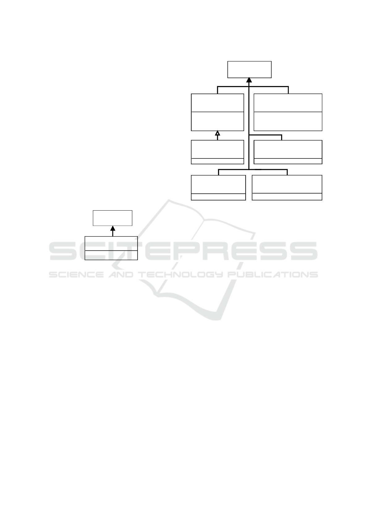
2.2 Value Variants
The second extended UML meta class is Property,
which is used to specify properties of classes. Fig-
ure 2 presents all Property extending stereotypes.
Properties can be classified into value-based and
instance-based properties. Value-based properties are
specified by primitive data types (comparable to sim-
ple linear or numerical design parameters) or enumer-
ations. Their properties can be modified for variant
specification. Thus, the set of stereotypes for Property
is called valueVariant. In contrast to this, instance-
based properties are specified by associations and al-
low hierarchical variant specification of the associated
class, which is described in Section 2.3.
«Stereotype»
intervalValueVariant
min : Real [1]
max : Real [1]
step : Real [1]
«Stereotype»
typeValueVariant
type : DataType [1]
values : ValueSpecification [*]
isOrdered : Boolean [1]
«Stereotype»
listValueVariant
«Stereotype»
derivedValueVariant
formula : Behavior [1]
«Stereotype»
fixedValueVariant
value : ValueSpecification [0..1]
«Stereotype»
optionalValueVariant
«Metaclass»
UML::Property
Figure 2: Profile diagram for value variants.
Property is classified into several categories: nu-
merical attributes, optional attributes, enumeration-
based attributes, fixed attributes or derived attributes.
For each category, a separate stereotype is defined,
which owns different properties to specify the vari-
ants of corresponding Property element.
First of all, a system architecture may have com-
ponent properties, which are important for simulation
and evaluation of this architecture, but should not be
varied in the design space description. Such proper-
ties can apply the stereotype fixedValueVariant explic-
itly, but this is not mandatory. Properties without vari-
ant stereotype do not increase the design space and
thus are automatically interpreted as fixed. Stereotype
fixedValueVariant is thus defined as default. FixedVal-
ueVariant includes property value of type ValueSpeci-
fication, which allows static configuration of Property
values for system architecture variant models. Value
is an optional stereotype property allowing to set a
value to be assigned to this property.
Defining a set of valid values is another possibil-
ity to specify value variants of a Property element.
Each value of this set can be assigned to a class prop-
erty. We propose the stereotype typeValueVariant for
this case, which allows the definition of a value list,
whose items confirm to the type of its Property. For
that, the stereotype typeValueVariant owns three prop-
erties: type specifies the data type, whose value are set
to the list and thus defines the type of the list, while
values represents a set of actual values (like an enu-
meration). Additionally, typeValueVariant owns the
boolean property isOrdered, which indicates whether
MODELSWARD 2017 - 5th International Conference on Model-Driven Engineering and Software Development
420
any kind of sorted neighborhood relation is existing
inside values. Otherwise, the neighborhood relation
is assumed as chaotic.
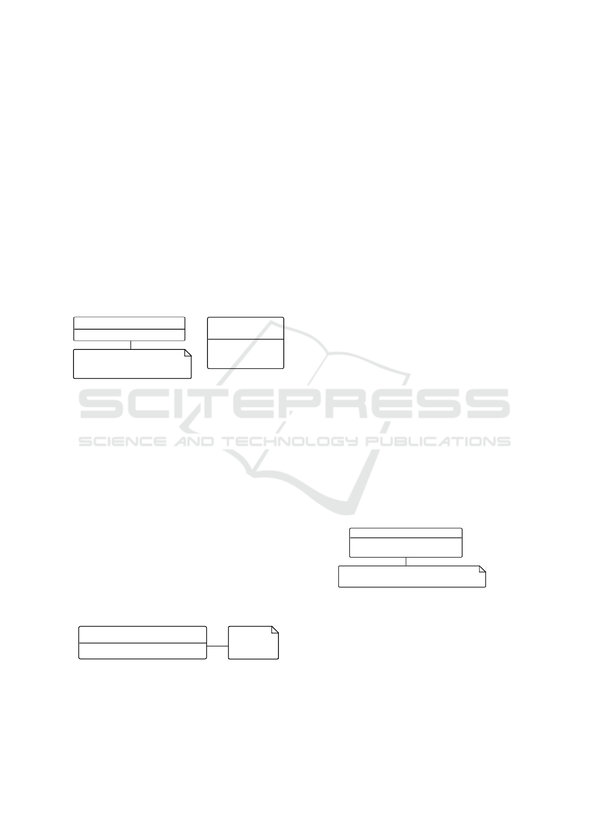
Figure 3 presents a simple example for the use
of typeValueVariant. The class A has a property b
with enumeration class enum as type. The enumer-
ation includes three literals option1, option2 and op-
tion3. Property b is specified with stereotype typeVal-
ueVariant. Thus, stereotype properties type and val-
ues should be set. The value of type must match with
type of b. This can be an instance of property type or
an instance of a derived class. Here, the enumeration
enum is used. Property values includes all value vari-
ants, which can be assigned to b. Here, these value
variants must be a literal of enum. However, values
does not have to contain all existing literals, but only
literals which are relevant for the current variant spec-
ification. Thus, values is filled with enumeration lit-
erals option1 and option2.
«enumeration»
enum
option1
option2
option3
type = <enumeration> enum
values = {option1,option2}
isOrdered = true
A
«typeValueVariant» b : enum [1]
Figure 3: Example for use of typeValueVariant.
Variants of numerical properties may be speci-
fied by interval definitions with minimal and maxi-
mal value as well as a step definition to specify all
intermediate values. For that, stereotype intervalVal-
ueVariant is introduced to describe the range of nu-
merical values of Property. The range is restricted by
a minimal value (min) and maximal value (max). The
values between these limits are calculated using the
property step.
An example for application of stereotype interval-
ValueVariant is presented in Figure 4. A class A owns
a real number b, which should be varied. For that, the
stereotype intervalValueVariant is applied to b and its
properties have to be set. The property b should be
able to take values from 0 to 2.5 with accuracy of
one decimal digit. Thus, the property min is set to
0.0 and max to 2.5. The accuracy is specified with
property step, which is set to 0.1. Thus, the values
0.0, 0.1, ..., 2.4, 2.5 can be assigned to property b.
A
«intervalValueVariant» b : Real [0..1]
min = 0.0
max = 2.5
step = 0.1
Figure 4: Example for intervalValueVariant.
The length of list properties can be assumed as s
special case of numerical attributes. Instead of as-
signing a value to a Property, a value can represent
the number of elements inside the Property. How-
ever, the changed interpretation of variant specifica-
tion requires the additional stereotype listValueVari-
ant, which is derived from intervalValueVariant and
inherits its properties. This stereotype only specifies
the count of values inside a Property element, but
does not have information about the value specifica-
tions. This has to be done by another stereotype.
Furthermore, a system component may have op-
tional features, which are represented by Boolean val-
ues specified in Property and thus can assume either
the value true or false. Exactly such a variant specifi-
cation is realized with stereotype optionalValueVari-
ant. Properties for optionalValueVariant are not spec-
ified, because further information for this stereotype
is not necessary.
System components may have properties, which
depend on other properties and can be calculated ex-
plicitly based on the value of such properties. Such
variants are specified with the stereotype derivedVal-
ueVariant (to simplify their later calculation, which
otherwise could be done with constraints in a much
less efficient generate-and-test algorithm). Its prop-
erty formula describes the calculation function. For-
mula is a Behavior, which is the basic meta class
for all behavioral (executable) elements of the UML.
Thus, the formula can be described by using UML di-
agrams like Activity Diagram or Sequence Diagram.
Furthermore, OpaqueBehavior or FunctionalBehav-
ior can be used to specify the behavior with code
fragments of programming languages or expressions
of OMG’s Meta Object Facility Model to Text Trans-
formation Language (MOFM2T (OMG, 2008)). The
specified behavior can be executed and the result is as-
signed to the corresponding Property afterwards. The
actual behavior for formula has to be specified during
the variants modeling.
A
«derivedValueVariant» b : Integer [1]
c : Integer [1] = 10
formula=<FunctionBehavior>calculateB
calculateB.body = self.c % 10
Figure 5: Example for derivedValueVariant.
Figure 5 shows an example class A with property
b and c. The value of b should be calculated based
on the value of c. For that, the stereotype derived-
ValueVariant is applied to b. Its calculation formula
is specified inside the stereotype property formula,
which can be described using MOFM2T expressions
for instance. All instances and values of the current
system architecture variant can be used for the calcu-
lation. Here, MOFM2T expression is specified inside
A UML Profile for the Specification of System Architecture Variants Supporting Design Space Exploration and Optimization
421
a FunctionBehavior and calculates the modulo value
of c. The result of MOFM2T expression processing
is assigned to b.
These stereotypes suffice to describe all possibili-
ties for specifying variants of properties that we have
encountered so far in our analysis. The more complex
description of instance variants is covered next.
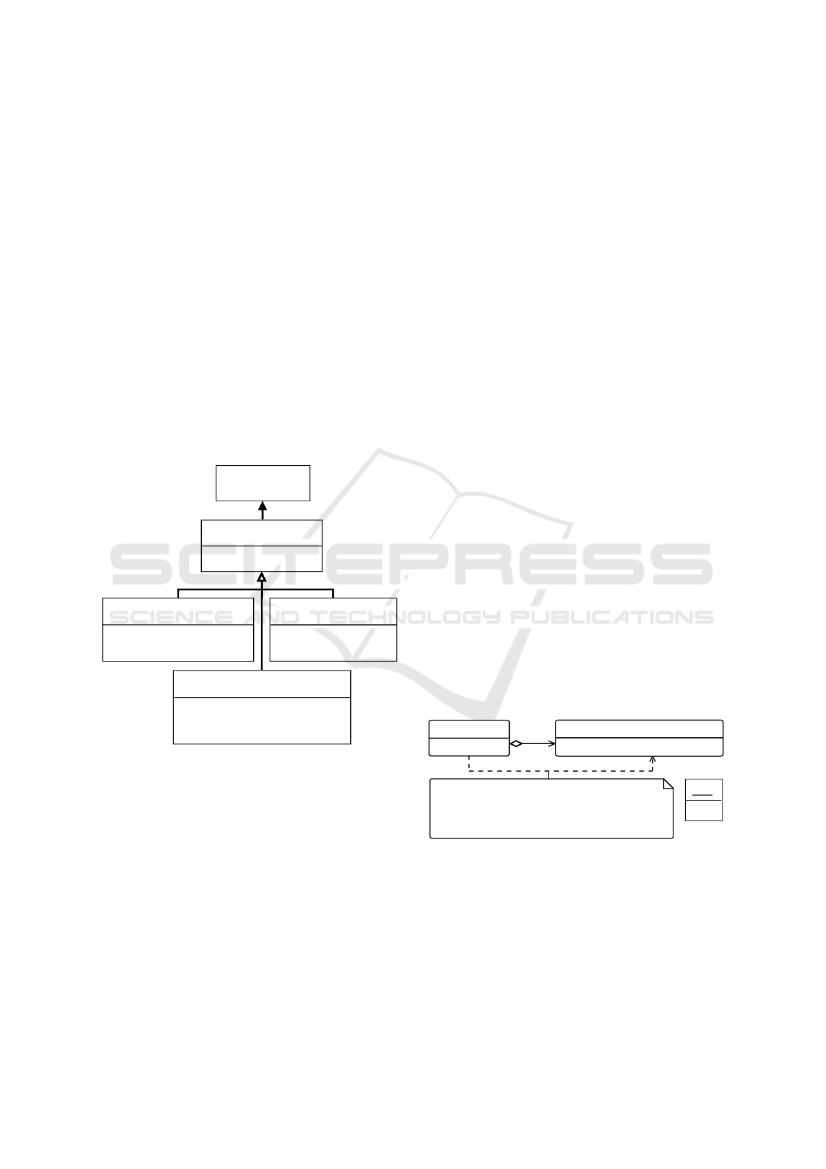
2.3 Instance Variants
The UML meta class Dependency is extended with
variant stereotypes in order to vary instance-based
properties, which are specified by associations to
other classes. A Dependency relation defines that a
class depends on a single supplier class or set of sup-
plier classes (OMG, 2015). Figure 6 shows the in-
troduced stereotypes, which extend the Dependency
class. These stereotypes define, how many instances
of the supplier class should be created and how their
properties have to be set.
«Stereotype»
derivedInstanceVariant
creationBehavior : Behavior [1]
oppositeTarget : Property [0..1]
variantClass : Class [*]
«Stereotype»
instanceVariant
target : Property [1]
uniqueInstances : Boolean [1]
«Metaclass»
UML::Dependency
«Stereotype»
countFixedInstanceVariant
instanceCount : Integer [1]
instanceList : InstanceSpecification [*]
«Stereotype»
countVariableInstanceVariant
minimalCount : Integer [1]
maximalCount : Integer [1]
step : Integer [1]
instanceList : InstanceSpecification [*]
Figure 6: Profile diagram for instance variants.
In general, variant specification of instance-based
properties defines, that instances of a supplier class
should be assigned to a property of the depending
class. How many instances should be created and
how these instances are configured, should be defined
through specializations.
The meta class Dependency is extended by the
stereotype instanceVariant, which implies, that a de-
pendent class includes instances of the supplier class.
These instances are assigned to the property of the de-
pendent class, with is configured in stereotype prop-
erty target. The second Property of instanceVariant is
called uniqueInstances and implies that the instances
are unique w.r.t. their values.
Further stereotypes are derived from this base
stereotype and specify the number of instances and
their property settings. The properties of instance-
Variant are inherited and thus configurable by derived
stereotypes.
The number of instances can be fixed or variable
for variant specification. In the fixed case, a prede-
fined number of supplier class instances has to be as-
signed to a property of the depending class. Further-
more, these fixed instances have attributes, which may
be fixed or variable. For that, the derived stereotype
countFixedInstanceVariant is introduced. It implies
that a fixed number of instances of the supplier class
should be created and assigned to the inherited Prop-
erty target. The count of instances is specified with
Property instanceCount. A created instance has prop-
erties, to which a value has to be assigned. These
values can be determined by a fixed or variable speci-
fication. In order to cover all combinations of variant
specifications, three possibilities including value set-
ting behavior are defined, and priorities assigned to
them as follows.
The preferred (high priority) option is the con-
figuration of fixed instance specifications inside the
stereotype countFixedInstanceVariant. For that, the
optional Property instanceList is defined, which is a
set of InstanceSpecification elements, which includes
slots for values specifications of class properties. It
may be that an InstanceSpecification is incomplete,
because at least one value of an attribute is not pre-
configured. In this case, the second option is checked,
in which the value should be determined based on
stereotype specifications. If the property does not ap-
ply a stereotype, specified default values of the prop-
erty should be used. If none of the options is applica-
ble, the property value stays undefined.
A
b : B [*]
B
«intervalValueVariant» a : Integer [1]
<<countFixedInstanceVariant>>
b[*]
target = <Property> A::b
uniqueInstances = true
instancesCount = 2
instanceList = {<InstanceSpecification> s}
s:B
c = 5
Figure 7: Example for countFixedInstanceVariant.
An example is shown in Figure 7: Two classes A
and B are connected through a composite association,
in which class A includes instances of class B. Addi-
tionally, class B has a numeric property c. The variant
profile should be used to specify that A owns two in-
stances of B, in which one instance has a fixed value 5
for c. The second instance’s attribute can be varied
between 0 and 10, but has to be different from the first
MODELSWARD 2017 - 5th International Conference on Model-Driven Engineering and Software Development
422
instance’s value. To specify that, a Dependency con-
nection is created between target class A and supplier
class B, which applies the stereotype countFixedIn-
stanceVariant. The stereotype property target speci-
fies the property of the target class, to which the cre-
ated instances should be assigned. Here, the instances
are assigned to the property b of class A. UniqueIn-
stances is set to true, because the instances inside b
should be different. Class A should own two instances
of B, thus instanesCount is set to 2. The fixed instance
is specified with InstanceSpecification s, which assign
the value 5 to property c. This InstanceSpecification
is assigned to stereotype property list. The stereotype
intervalValueVariant is applied to property c in order
to specify the variants of class B.
According to the specified value-setting behavior,
an instance of class A is created and its properties are
configured based on the applied stereotypes. Two in-
stances of class B are created afterwards. The precon-
figured instance specifications of class B are used first.
The second instance is not specified by instanceList.
Thus, the remaining instances are created based on
variant specification of class B, in which the value of
property c may be set to 9, for instance.
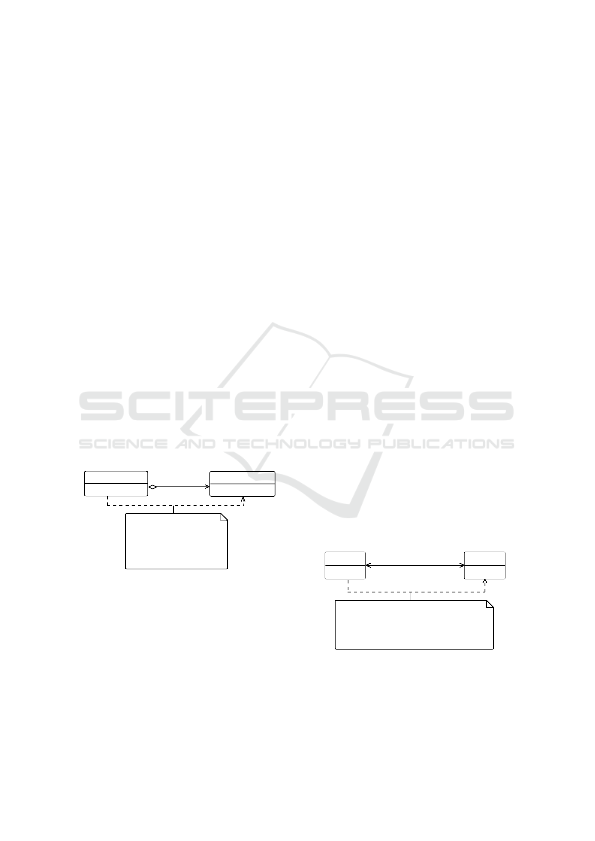
In contrast to countFixedInstanceVariant, the
stereotype countVariableInstanceVariant is used for
variable quantities of class instances. Variants of in-
stance quantities are restricted by the stereotype prop-
erties minimalCount and maximalCount. The values
between these limits are calculated based on steps.
Property values of each class instance are calculated
in the same way as for countFixedInstanceVariant.
A
b : B [*]
B
c : Integer [1] = 1
<<countVariableInstanceVariant>>
b[*]
target = <Propert> A::b
uniqueInstance = false
minimalCount = 1
maximalCount = 5
step =1
instanceList = {}
Figure 8: Example for countVaribleInstanceVariant.
Figure 8 presents an example for the application of
stereotype countVaribleInstanceVariant to the same
system as in Figure 7. Class A should include one to
five instances of class B. Instances of class B are not
predefined, but the property of B is fixed to 1. Thus,
a Dependency connection with stereotype countVari-
ableInstanceVariant is created between classes A and
B. The stereotype target is set again to A::b. Class B
should not be varied; thus all instances have the same
value for c and the property uniqueInstances must be
set to false. At least one instance of B has to exist, but
not more than five of them together. For this, mini-
malCount is set to 1, maximalCount to 5, and step to
1. The list of preconfigured instances remains empty,
because instance specifications are not used here.
Creation of class instances may depend on already
existing instances of other classes. This can be the
creation of a communication connection between two
component classes, for instance. If a communication
link can be created, it may depend on properties of the
connected components (modeled as class instances),
which cannot be evaluated during variant specifica-
tion. This has to be done at run time of the later vari-
ant creation. The required behavior to create an in-
stance of the supplier class has to be defined inside
the system architecture variants model.
For that, the stereotype derivedInstanceVariant
has to be applied. DerivedInstanceVariant implies
that the supplier class is created based on information
from the depending class. How the supplier instances
should be created, is specified in stereotype property
creationBehavior, which is a Behavior. CreationBe-
havior can be specified by any UML behavioral ele-
ment like Activity Diagram or FunctionBehavior. The
specified behavior is executed for each unique combi-
nation of depending instance specifications.
For the special case of bidirectional associations
between classes, the optional Property oppositeTar-
get is introduced, which specifies a property of the
supplier class. It expresses that the bidirectional as-
sociation should be created, in which instances of a
depending class should be assigned to the property
oppositeTarget and the created supplier class instance
should be assigned to the target class property target.
Furthermore, oppositeTarget allows the restriction of
instance combinations as input for the behavior. For
instance, a Dependency is linked to a class with an
opposite target-property, which required exactly two
instances of the class. Thus, only combinations with
two different class instances have to be investigated.
A
b : B [*]
B
a : A [1]
<<derivedInstanceVariant>>
a[1]
b[*]
target = <Property> A::b
uniqueInstances = false
creationBehavior = <Activity> createB
variantClass = {B}
oppositeTarget = <Property> B::a
Figure 9: Example for derivedInstanceVariant.
A derivedInstanceVariant-applied Dependency is
presented in Figure 9. Class A and B are associated
bidirectionally, in which class B depends on class A.
Class A owns several instances of B, but class B in-
A UML Profile for the Specification of System Architecture Variants Supporting Design Space Exploration and Optimization
423
cludes only one instance of A. Thus, the Dependency
is created from A to B. The stereotype derivedIn-
stanceVariant is applied. The property target is set
to A::b and oppositeTarget to B::a in order to real-
ize the bidirectional association. The creationBehav-
ior is specified by Activity createB, which creates an
instance of B. The property variantClass defines pos-
sible classes, which could be created during the opti-
mization process. Here, only instances of class B can
be created and thus, B is assigned to variantClass.
These stereotypes form the variant profile and al-
low design space descriptions of system architectures.
3 AN APPLICATION EXAMPLE
The presented profile for modeling system architec-
ture variants from Section 2 is applied to a commu-
nication network, where nodes shall send and receive
data using certain communication protocols.
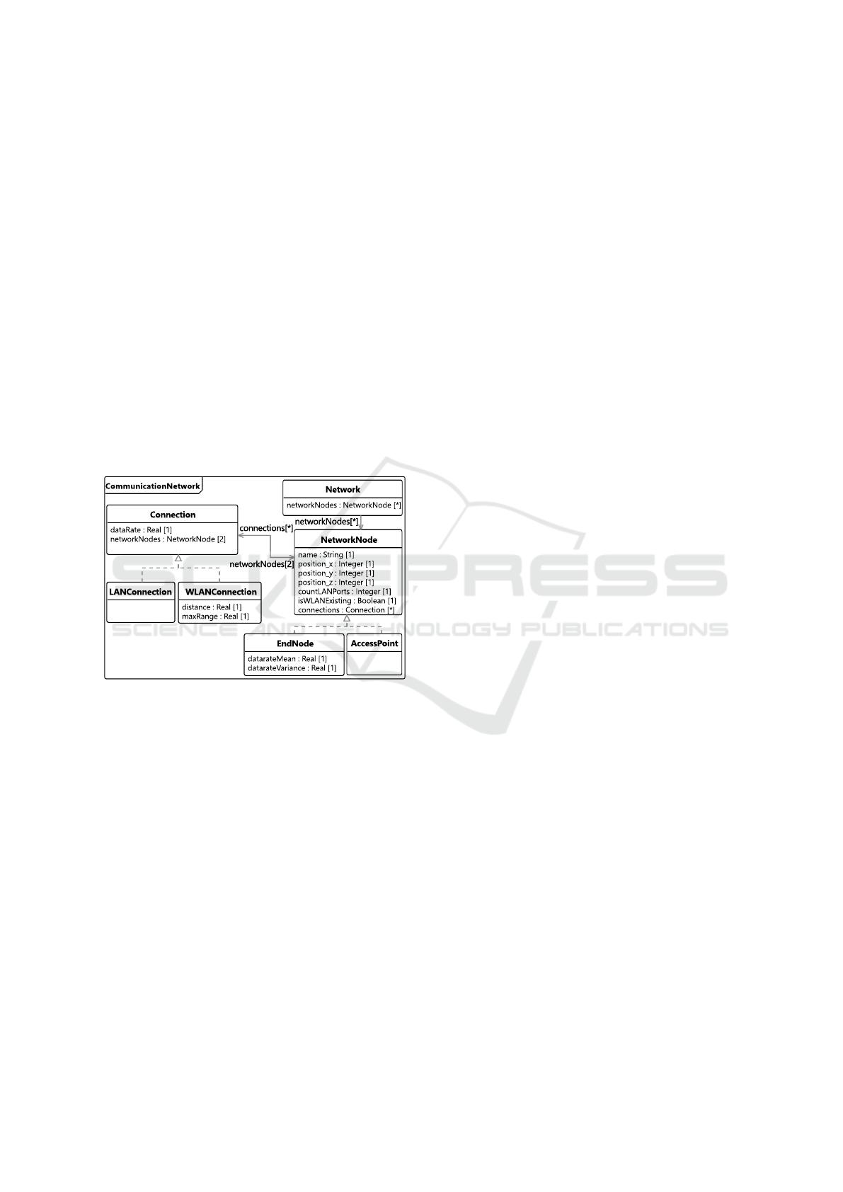
Figure 10: Design of communication network.
The class diagram of the system design is pre-
sented in Figure 10. The communication network
is represented by the class Network. Network nodes
are modeled as interfaces to provide basic properties,
which are necessary for all nodes. A network node
has a name and a position in three-dimensional space
as well as nonrecurring and ongoing costs. Commu-
nication with other nodes is realized over a connec-
tion interface, which is implemented by an Ethernet
or WLAN connection and can transfer data according
to its Property dataRate. Network nodes may provide
Ethernet slots or WLAN technique to be able to com-
municate. The connection realization WLANConnec-
tion has additional properties to specify the maximal
communication range and store the actual distance be-
tween two network nodes. Each connection describes
communication between two NetworkNode objects.
Network nodes can have more than one connec-
tion to different nodes depending on their Ethernet
slots and WLAN features. Connections between two
nodes are limited to one. The NetworkNode inter-
face is realized by classes EndNode and AccessPoint.
EndNodes represent machines like server, personal
computer or smart phones. They produce data with
a Gaussian distributed data rate and send this to con-
nected nodes, while also receiving data. AccessPoints
serve as transmission nodes and transfer received data
to target nodes or another AccessPoint.
The design space of this system should be de-
scribed in order to be used by a system architecture
optimization process. The variant profile is assigned
to the communication network model in order to de-
fine which elements of this model can be varied.
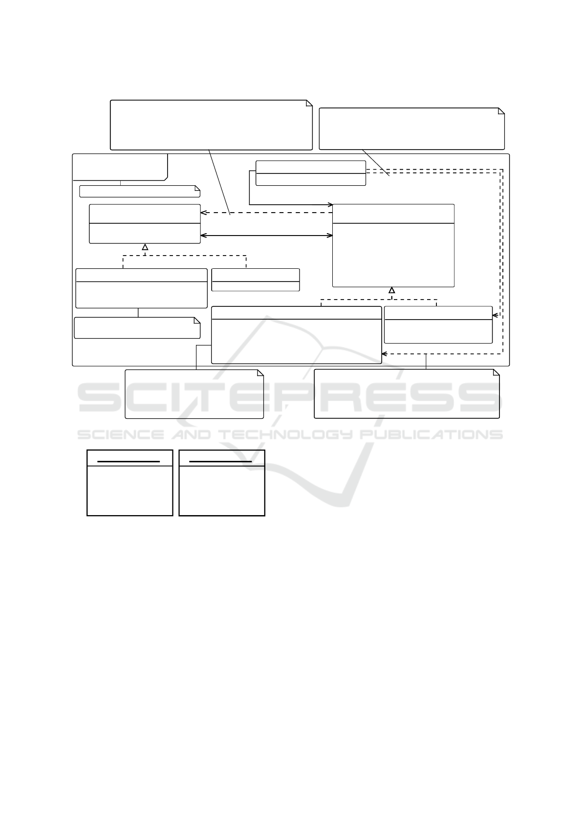
Figure 11 presents the resulting architecture vari-
ant model of the communication network. First of all,
the model CommunicationNetwork applies stereotype
variant. Its property rootClass is set to Class Commu-
nicationNetwork, because creation of an architecture
variant should start with this class.
Dependency connections are defined and specified
with stereotypes afterwards. EndNodes should not be
varied. The example considers one personal computer
and one smart phone. The personal computer has one
Ethernet port but no WLAN option, while the smart
phone provides WLAN connections, but has no Eth-
ernet ports. Both are placed in different positions.
For that, a Dependency is created from Network to
EndNode and stereotype countFixedInstanceVariant
is assigned to this connection. The specification of
this two EndNode instances is presented in Figure 12.
InstanceSpecifications are used to define proper-
ties of existing nodes. They are assigned to stereo-
type property instanceList. Furthermore, objectCount
is set to value 2, all instances should be unique. Net-
work::networkNodes is specified as target.
AccessPoints are variable in quantity and property
configuration. They are used to implement communi-
cation between computer and smart phone. For that,
Network and AccessPoint are connected by a Depen-
dency with applied stereotype countVariableInstance-
Variant. Network includes at least zero and not more
than three AccessPoints objects. A instanceList is not
set. Thus, values of instances are set based on value
variant specification or default value of properties.
A Dependency with applied stereotype includeD-
erivedObjects is created between interfaces Networ-
kNode and Connection. References of this connec-
tion are stored inside NetworkNode::connections and
references of nodes should be deposited in Connec-
tion::networkNode. A connection can be realized by
classes WLANConnection and LANConnection. The
property variantClass is specified with both classes,
which implicates, that instances of these classes could
MODELSWARD 2017 - 5th International Conference on Model-Driven Engineering and Software Development
424
«variant»
CommunicationNetwork
EndNode
datarateMean : Real [1] = 5.0
datarateVariance : Real [1] = 50.0
«interface»
Connection
dataRate : Real [1]
networkNodes : NetworkNode [2]
WLANConnection
«derivedValueVariant» distance : Real [1]
maxRange : Real [1] = 50.0
dataRate : Real [1] = 50.0
Network
networkNodes : NetworkNode [*]
AccessPoint
«intervalValueVariant» countLANPorts : Integer [1]
«optionalValueVariant» isWLANExisting : Boolean [1]
«intervalValueVariant» position_x : Integer [1]
«intervalValueVariant» position_y : Integer [1]
«intervalValueVariant» position_z : Integer [1]
LANConnection
dataRate : Real [1] = 100.0
«interface»
NetworkNode
name : String [1]
position_x : Integer [1]
position_y : Integer [1]
position_z : Integer [1]
countLANPorts : Integer [1] = 0
isWLANExisting : Boolean [1] = false
connections : Connection [*]
<<countFixedInstanceVariant>>
<<countVariableInstanceVariant>>
<<derivedInstanceVariant>>
networkNodes[2]
connections[*]
networkNodes[*]
rootClass = <class> Network
target = <Property> NetworkNode::connections
uniqueInstances = true
creationBehavior = <Activity> CreateConnection
variantClass = {WLANConnection, LANConnection}
oppositeTarget = Connection::networkNodes
target = <Property> Network::networkNodes
uniqueInstances = true
instanceCount = 2
instanceList = {node1, node2}
formula = <FunctionBehavior>
calculateDistance
min max step
countLANPorts 0 4 1
position_x 0 1000 200
position_y 0 500 100
positoin_z 0 200 100
target = <Property> Network::networkNodes
minimalCount = 1
maximalCount = 3
step = 1
instanceList = {}
Figure 11: Architecture variants model of communication network.
node1:EndNode
name = "smart phone"
isWLANExisting = true
postion_x = 250
position_y = 50
position_z = 100
node2:EndNode
name = "computer"
countLANPorts = 1
postion_x = 650
position_y = 450
position_z = 100
Figure 12: Fixed instance specifications of EndNode.
be created by this variant description.
A connection should be established between two
nodes. This can be done using WLANConnection or
LANConnection instances. Both connection classes
have requirements to the NetworkNode instances,
which must be fulfilled in order to be created. A LAN-
Connection requires a free LAN port on each network
node for instance. For that, stereotype includeDerive-
dObjects requires a Behavior specification, which de-
scribes the requirements of each Connection realizing
class and the behavior, which connection class should
actually be created.
Value variant stereotypes are applied to properties
of classes AccessPoint and WLANConnection. The
property Distance of class WLANConnection is a de-
rived property and applies stereotype derived. A for-
mula is specified with MOF Model to Text Transfor-
mation Language expression and calculates the dis-
tance between two NetworkNode instances, which are
set in networkNodes. The class AccessPoint inher-
its all properties of the interface NetworkNode. The
following properties are overwritten and stereotypes
are applied to them: Property countLANPorts ap-
plies the stereotype intervalValueVariant. An Access-
Point can have no Ethernet port up to four Ether-
net ports. Accordingly, the stereotype properties are
set. The optionalValueVariant stereotype is applied
to isWLANExisting indicating if an AccessPoint can
provide WLAN connections or not. The position at-
tributes of AccessPoint applies the intervalValueVari-
ant stereotype and the valid coordinates are specified.
Finally, all value-based properties without variant
stereotypes could be assigned a default value. This
completes the system architecture variants model, and
an optimization process could use this model of the
design space to find an optimal system architecture.
A UML Profile for the Specification of System Architecture Variants Supporting Design Space Exploration and Optimization
425

4 CONCLUSION
This paper presented an approach for the model-based
specification of system architecture variants, thus al-
lowing the concise specification of the complex de-
sign space of a system with architecture variations. A
UML profile is introduced for this task, which extends
standard UML meta model elements with variant-
specific stereotypes. This allows variant specifica-
tions of system architectures, which are necessary to
execute system architecture optimizations automati-
cally or to apply other methods which require an im-
plicit design space description.
Future steps include the specification and imple-
mentation of a generator, which creates architectures
based on the architecture variants model affected by
decisions made during an optimization heuristic exe-
cution. Furthermore, constraints should be added to
the variant model in order to validate sytem variants.
REFERENCES
Acher, M., Cleve, A., Collet, P., Merle, P., Duchien, L., and
Lahire, P. (2014). Extraction and evolution of archi-
tectural variability models in plugin-based systems.
Software & Systems Modeling, 13(4):1367–1394.
Association, E.-A. (2013). EAST-ADL domain model spec-
ification version V2.1.12. Technical report, EAST-
ADL Association.
AUTOSAR (2015). AUTOSAR specification. Online. Re-
lease 4.2.
Bedini, F., Maschotta, R., Wichmann, A., J
¨
ager, S., and
Zimmermann, A. (2017). A model-driven C++-
fUML execution engine. In 5th Int. Conference on
Model-Driven Engineering and Software Develop-
ment, MODELSWARD 2017. Technische Universit
¨
at
Ilmenau. accepted for publication.
Broy, M., Gleirscher, M., Merenda, S., Wild, D., Kluge, P.,
and Krenzer, W. (2009). Toward a Holistic and Stan-
dardized Automotive Architecture Description. COM-
PUTER, 42(12):98–101.
Clements, P. C. (1996). A Survey of Architecture Descrip-
tion Languages. In Proceedings of the 8th Interna-
tional Workshop on Software Specification and De-
sign, IWSSD ’96, pages 16–, Washington, DC, USA.
IEEE Computer Society.
Dashofy, E., van der Hoek, A., and Taylor, R. (2001).
A highly-extensible, XML-based architecture descrip-
tion language. In Software Architecture, 2001. Pro-
ceedings. Working IEEE/IFIP Conference on, pages
103–112.
Eclipse (2014). Sirius. http://www.eclipse.org/sirius/.
This work was supported by the Federal Ministry of
Economic Affairs and Energy of Germany [20K1306D] and
Federal Ministry for Education and Research of Germany
[01S13031A].
El Kouhen, A., Dumoulin, C., Gerard, S., and Boulet,
P. (2012). Evaluation of modeling tools adapta-
tion. Available: https://hal.archives-ouvertes.fr/hal-
00706701.
Garlan, D., Monroe, R., and Wile, D. (2010). Acme: An ar-
chitecture description interchange language. In CAS-
CON First Decade High Impact Papers, CASCON
’10, pages 159–173, Riverton, NJ, USA. IBM Corp.
Gr
¨
onninger, H., Krahn, H., Pinkernell, C., and Rumpe, B.
(2014). Modeling variants of automotive systems us-
ing views. In Tagungsband Modellierungs-Workshop
MBEFF: Modellbasierte Entwicklung von eingebet-
teten Fahrzeugfunktionen.
OMG (2008). MOF model to text transformation language
1.0. Technical report, Object Management Group.
OMG (2015). Unified modeling language (OMG UML),
version 2.5. Technical report, Object Management
Group.
Oquendo, F. (2004). µADL: An architecture description
language based on the higher-order typed π-calculus
for specifying dynamic and mobile software architec-
tures. SIGSOFT Softw. Eng. Notes, 29(3):1–14.
Schobbens, P.-Y., Heymans, P., and Trigaux, J.-C. (2006).
Feature diagrams: A survey and a formal semantics.
In 14th IEEE International Requirements Engineering
Conference (RE’06), pages 139–148. IEEE.
Systems and Software Engineering Group (2016). Model
Driven Engineering for C++ (MDE4CPP), sse.tu-
ilmenau.de/mde4cpp.
Taghavi, T. and Pimentel, A. (2010). Visualization of multi-
objective design space exploration for embedded sys-
tems. In Digital System Design: Architectures, Meth-
ods and Tools (DSD), 2010 13th Euromicro Confer-
ence on, pages 11–20.
van Leeuwen, C., de Gier, J., de Filho, J. O., and Papp,
Z. (2014). Model-based architecture optimization for
self-adaptive networked signal processing systems. In
SASO 2014 - 8th IEEE International Conference on
Self-Adaptive and Self-Organizing Systems.
Wichmann, A., J
¨
ager, S., Jungebloud, T., Maschotta, R.,
and Zimmermann, A. (2015). System architecture op-
timization with runtime reconfiguration of simulation
models. In IEEE International Systems Conference
(SYSCON15). Technische Universit
¨
at Ilmenau.
Wichmann, A., J
¨
ager, S., Jungebloud, T., Maschotta, R.,
and Zimmermann, A. (2016). Specification and ex-
ecution of system otimization processes with UML
activity diagrams. In IEEE International Systems
Conference (SYSCON16). Technische Universit
¨
at Il-
menau.
Zak
´
al, D., Lengyel, L., and Charaf, H. (2011). Software
Product Lines-based development. In Applied Ma-
chine Intelligence and Informatics (SAMI), 2011 IEEE
9th International Symposium on, pages 79–81.
MODELSWARD 2017 - 5th International Conference on Model-Driven Engineering and Software Development
426
