
Event Classification from Sensor Data using Spectral Analysis in Robotic
Finishing Processes
Bobby K. Pappachan
1
, Tegoeh Tjahjowidodo
2
and Tomi Wijaya
1
1
Rolls-Royce @ NTU Corporate Lab c/o, Nanyang Technological University, 65 Nanyang Avenue, Singapore, Singapore
2
Nanyang Technological University, Singapore, Singapore
Keywords:
Machining, Finishing, Passes, Welchs Estimate.
Abstract:
Process monitoring using indirect methods leverages on the usage of sensors. Using sensors to acquire vital
process related information also presents itself with the problem of big data management and analysis. Due to
uncertainty in the frequency of events occurring, a higher sampling rate is often used in real-time monitoring
applications to increase the chances of capturing and understanding all possible events related to the process.
Advanced signal processing methods helps to further decipher meaningful information from the acquired
data. In this research work, power spectrum density (PSD) of sensor data acquired at sampling rates between
40 kHz-51.2 kHz was calculated and the co-relation between PSD and completed number of cycles/passes is
presented. Here, the progress in number of cycles/passes is the event this research work intends to classify
and the algorithm used to compute PSD is Welchs estimate method. A comparison between Welchs estimate
method and statistical methods is also discussed. A clear co-relation was observed using Welchs estimate to
classify the number of cyceles/passes.
1 INTRODUCTION
In machining processes, ensuring the quality of a fin-
ished product is crucial and with advances in man-
ufacturing technology, a need exists to integrate in-
process monitoring technology into the production
environment, so as to avoid manufacturing induced
anomalies (G. Byrne and Teti, 1999; D. Dornfeld
and Vijayaraghavan, 2009). Advanced process mon-
itoring technology coupled with an intelligent deci-
sion making support system can reduce the time taken
to otherwise perform rework on finished components
with defects. This will save costs and also reduce
the dependency on skilled operators. A report re-
leased by the Federal Aviation Authority (FAA) in
partnership with the Aerospace Industries Association
(AIA) Rotor Manufacturing (RoMan) Project Team in
the year 2006, stresses the importance of incorporat-
ing advance process monitoring and control technol-
ogy in manufacturing processes especially for critical
aerospace components (Team, 2006). Process mon-
itoring is generally classified into direct and indirect
methods. In direct method, the quantity of the output
variable is measured or monitored directly whereas
in indirect method, the output variable is deduced
through monitoring the quantity of process variables
such as vibration, speed (P. Stavropoulos and Chrys-
solouris, 2013). While direct method is known for
its accuracy, indirect method is widely accepted since
they are more realistic to be implemented in an indus-
trial environment as the cost incurred is comparatively
less than direct method. Indirect process monitor-
ing is performed by capturing these process variables
with the means of sensor systems for e.g., accelerom-
eter, dyanamometer, temperature sensor etc. Standard
data acquistion (DAQ) systems are then used to ac-
quire, sample and log the data. The data is further
analysed to identify any significant and/or persisting
trend/patterns. Subsequently, the analysed data can
be used to deduce the required output variable. This
analysis can also be performed real-time making indi-
rect method more efficient than direct methods. A im-
portant step involved in the data analysis is to identify
the signal signature. This paper focuses on identify-
ing a relevant signature that gives direct information
of the progress of machining process. In the sections
following, an overview of sensor based monitoring
and signal processing methods in machining applica-
tions is presented. Sections 3 and 4 covers the exper-
iment setup under which this research work was per-
formed, the results received and inferences deduced
from the results.
80
Pappachan B., Tjahjowidodo T. and WIjaya T.
Event Classification from Sensor Data using Spectral Analysis in Robotic Finishing Processes.
DOI: 10.5220/0006204900800086
In Proceedings of the 6th International Conference on Sensor Networks (SENSORNETS 2017), pages 80-86
ISBN: 421065/17
Copyright
c
2017 by SCITEPRESS – Science and Technology Publications, Lda. All rights reserved
2 PROCESS MONITORING IN
MACHINING
Machining is the term used for manufacturing pro-
cesses that involves varying range of material re-
moval rate (MRR). Machining performed with hard
tool/cutter has higher material removal rate compared
with finishing processes wherein compliant abrasive
tools/brushes/belts are used. In a machining process
monitoring system as shown in figure 1, the cutting
region comprises of several process variables, such as
vibrations, cutting forces, acoustic emission, temper-
ature, surface finish. The various factors that influ-
ence these process variables include the state of the
cutter/tool, coolant flow, chip packing and other ma-
terial removal process conditions.
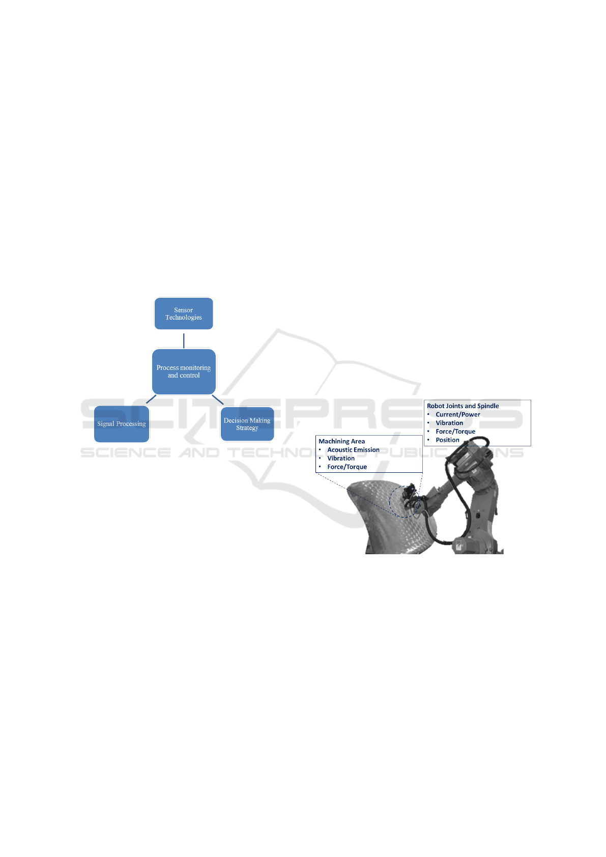
Figure 1: Building blocks of machining process monitor-
ing(Indirect).
By using appropriate physical sensors, the vari-
able that needs to be measured can be continually
monitored and variations can be logged (R. Teti and
Dornfeld, 2010). The data acquired is processed with
the aim to identify patterns, trends or abnormal pro-
cess conditions. Further analysis is performed on the
acquired data with the help of machine learning algo-
rithms such as neural networks and fuzzy logic. Upon
detection of any process related information or pro-
cess faults, the information is communicated either
to the operator or fed directly to robot controller to
take relevant corrective/adaptive actions (R. Teti and
Dornfeld, 2010; C. Bisu and Cahuc, 2013). A ma-
jority of past research works on process monitoring is
performed on processes involving hard tool, for e.g.
milling, turning. In most cases the focus of the work is
inclined towards tool condition monitoring (G. Byrne
and Teti, 1999). Focus of this research work is to
identify information that has some co-relation with
the completed number of passes in a robot assisted
finishing process. This was achieved by analyzing the
corresponding magnitude levels of frequency domain
signal from different passes and belonging to a fixed
frequency band. Further details on the experiment are
mentioned in section 3.
2.1 Sensing System and Signal
Processing
Some potential measurable process phenomena in a
robotic machining environment are shown in figure
2. Power and current flow of the spindle delivers
the required cutting force. Hence monitoring the
power intake and current flow in motors that drive the
spindle can be used to understand the MRR (G. W.
Fritz Klocke, 2008; Pritschow and Kramer, 2005).
However, in robot assisted finishing processes, mon-
itoring and implementing spindle drive control is im-
practical due to complex architecture compared with
traditional milling or turning machines or numerical
control (NC) machines. As shown in figure 2, mon-
itoring the measurable phenomena which are closer
to the machining area is a better alternative to under-
stand and analyse the nature of the process. This in-
clude acoustic emission (AE), force/torque exerted by
the tool on the workpiece, vibration and spindle mo-
tion displacement.
Figure 2: Measurable phenomena in machining environ-
ment.
Signal signatures often consist of embedded infor-
mation which can be co-related to process variable
itself. Signal processing plays a pivotal role in per-
forming this task by extracting the relevant signatures
and also to identify trends/patterns. Wide range of
signal processing techniques exists and choosing an
ideal technique relies heavily on the type of applica-
tion. Acoustic emission (AE) sensor is known for its
susceptibility towards high frequency signals (above
20 kHz) and clearly seems to be a favorite choice in
most machining process monitoring applications. Us-
ing AE sensor also reduces the requirement to per-
form further signature extraction as AE signal has
Event Classification from Sensor Data using Spectral Analysis in Robotic Finishing Processes
81

Table 1: Process monitoring classified based on monitoring
variable. (R. Teti and Dornfeld, 2010).
relatively higher signal to noise (S/N) ratio and im-
proved frequency response for high frequencies (Lee
and Dornfeld, 1998). However, in applications that
involve low material removal rate (MRR), magnitude
of elastic waves produced by tool-workpiece interac-
tion is much lower compared to processes like turn-
ing, milling, drilling etc. In such cases, other sensing
systems must be relied upon to give meaningful in-
formation regarding the process (e.g. Vibration sen-
sor). Table 1 gives a summary of past literature on
types of sensing system and signal processing used,
classified based on monitoring aspect. An exhaustive
review on process monitoring including the types of
sensors used and signal processing methods is given
in (R. Teti and Dornfeld, 2010). In our experiments
we have employed a tri-axial accelerometer to capture
vibration data.
2.2 Frequency Domain Analysis
Signal processing techniques can be broadly classi-
fied as time domain and frequency domain. Sev-
eral researches have used both techniques in appli-
cations involving tool wear/breakage detection and
indirect surface integrity detection. For instance, in
(T. I. El-Wardany and Elbestawi, 1996), kurtosis(time
domain) and frequency domain analysis is used suc-
cessfully to understand tool properties in a drilling
process. In time domain analysis, statistical meth-
ods are used to distinguish persisting patterns/trends.
This includes skewness, kurtosis, co-relation coeffi-
cient etc.In frequency domain analysis, captured sig-
nal is analyzed in the frequency domain and changes
to individual frequency components are often indica-
tive of the changes in process variables.
Frequency domain analysis also helps to visualize the
effect of noise filtering and various other window-
ing and filtering techniques. As the sampling fre-
quencies in this experiment falls in the range of 40-
51.2 kHz, performing time domain analysis proved to
be challenging due to the size of data captured and
hence frequency domain analysis was effective to un-
derstand process characteristics. Signal power also
contains pertinent information regarding the source of
signal generation. Conventionally, fast fourier trans-
form (FFT) can be used to determine power spec-
trum. In stochastic processes, performing FFT will
not be useful to reduce the noise embedded in the sig-
nal, hence some averaging needs to be performed to
increase the S/N ratio. Welch’s power spectrum esti-
mate essentially calculates power spectrum using FFT
coupled with averaging. This helps to minimise the
signal power caused by random variations. FFT do
not account in for discontinuities between successive
periods as the data captured is assumed to be of a sin-
gle period of a periodically repeating waveform and
this phenomenon is referred to as spectal leakage. Ap-
plying Welch’s estimate method also helps to reduce
spectral leakage and reduces the effect caused by un-
desired frequencies.
Welch’s method to compute PSD is performed by di-
viding the time series data into segments that are suc-
cessive and averaging the periodograms of each seg-
ments or frames. Consider x
m
(n) to be the input signal
where m = 0,1,..,K − 1,K = total number of frames
and n = 0,1,..,M − 1, periodogram of m th frame is
given by,
Px
m
,M(k) = 1/M |
N−1
∑
n=0
x
m
(n)e
−2πnk/N
|
2
(1)
then Welch’s power spectrum estimate is computed
as,
S
W
x
(w
k
) = 1/K
K−1
∑
m=0
Px
m
,M(k) (2)
Upon analyzing the power readings of certain fre-
quency components, it was noted that the changes
observed was corresponding to the completed num-
ber of passes. Analysing frequency component of
the vibration signal is imperative to finshing processes
as the fundamental frequency and its harmonics con-
tain coherent information which can be atributed to
spindle behavior and also the finshing of the compo-
nent. Shop floor operators require systems that are
less sophisticated and adopting a frequency domain
analysis method gives that flexbility as opposed to
other machine learning algorithms or statistical meth-
ods. Welch’s estimate method is preferred as an eas-
ier method to implement in such cases as it gives a
more visual means of interpretation. However, ma-
chine learning algorithms provide more stability in
applications involving predictive maintenance.
SENSORNETS 2017 - 6th International Conference on Sensor Networks
82

3 EXPERIMENT SETUP
The experiment setup (Fig. 3) comprises of an ABB
IRB 6660 machining robot and PDS colombo spin-
dle. The representative work coupon used for ma-
chining is a boss hole of combustor casing and the
objective is to remove the burrs until a chamfer is de-
veloped. As mentioned in section 2, vibration signa-
tures were measured using a tri-axial accelerometer,
Kistler 8763B (IEPE). The RPM of spindle was kept
constant at 10000 RPM and feed rate at 30mm/s. The
data acquisition devices used was NI cDAQ-9184 and
NI 9234 IEPE.
Figure 3: Trial and experiment setup.
3.1 Data Analysis and Results
Data was captured at a sampling rate of 40kHz and for
computational ease, pre-processed to 1000 samples
per each iteration of Welch’s estimate calculation. A
total of 12 sets of experiment was conducted with 8
being used for offline analysis and co-relation and an-
other 4 for validation. After each cycle of machin-
ing, the chamfer length was manually measured using
laser measuring device. In offline data analysis, co-
relation between the measured values and variations
in estimated power spectrum is analysed. The co-
relation between the power spectrum and number of
cycles was subsequently validated in real-time. Fig-
ure 4 shows the process flow of how experiments were
conducted.
Different data analysis techniques were used
on acquired data sets. For instance, kurtosis and
skewness values for respective passes were calculated
but it failed to show any consistent trend or pattern
with increasing number of passes. Table 2 shows cal-
culated kurtosis and skewness values for each pass. It
can be noted from the numbers that a pattern or trend
Figure 4: Process flow diagram.
Table 2: Kurtosis and Skewness Values.
is not obvious. This can also be also understood from
the figures 6 and 7.
Results obtained after performing Welch’s power
spectrum estimate is shown in figure 5. Figures 8, 9
and 10 shows the Welch’s power spectrum estimate at
1.297Khz. As shown in figures 8, 9 and 10, the power
values of vibration signal decreases with respect to
the increasing number of passes. The trend here when
compared with kurtosis and skewness values is more
obvious to the naked eye. The decrease in signal mag-
nitude is indicative of the strength of the signal. It is
also understood that the decrease in strength of sig-
nal is caused due to the smoothening of edges of boss
hole with increasing number of passes(Table 3 shows
the increase in chamfer radius with different pass).
From the vibration signatures, it can be concluded
that a co-relation exists with the different number of
passes and the PSD at 1.297 kHz. This signal is be-
lieved to be the 8th harmonic of the fundamental fre-
quency generated due to the spindle RPM. The spin-
dle RPM is controlled by a variable frequency drive
(VFD) controller and the frequency is fixed at 165 Hz.
This is however with the exception of Y axis measure-
Table 3: Increase in Chamfer Radius.
Event Classification from Sensor Data using Spectral Analysis in Robotic Finishing Processes
83
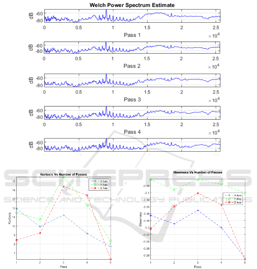
Figure 5: Welch’s Power Spectrum Estimate for each Pass/Cycles.
Figure 6: Kurtosis Vs Number of Passes.
ment and is caused due to the orientation and place-
ment of the sensor. Figure 11 shows the correlation
between magnitudes of the captured signal with in-
creasing number of passes. From the figure it can be
seen that, magnitude of vibration signal in Y axis is
relatively low as compared to X and Z axis measure-
ment which further confirms the assumption on sensor
location aspect.
Figure 7: Skewness Vs Number of Passes.
4 CONCLUSION
The focus of this experiment was to explore the re-
lationship between captured vibration signal and the
progress of the actual finishing process. The exper-
iment result establishes a linear co-relation between
vibration signals with completed number of passes.
One major limitation which the authors noted during
this research work is that, the results obtained were
dependent on the training experiments and hence ap-
SENSORNETS 2017 - 6th International Conference on Sensor Networks
84
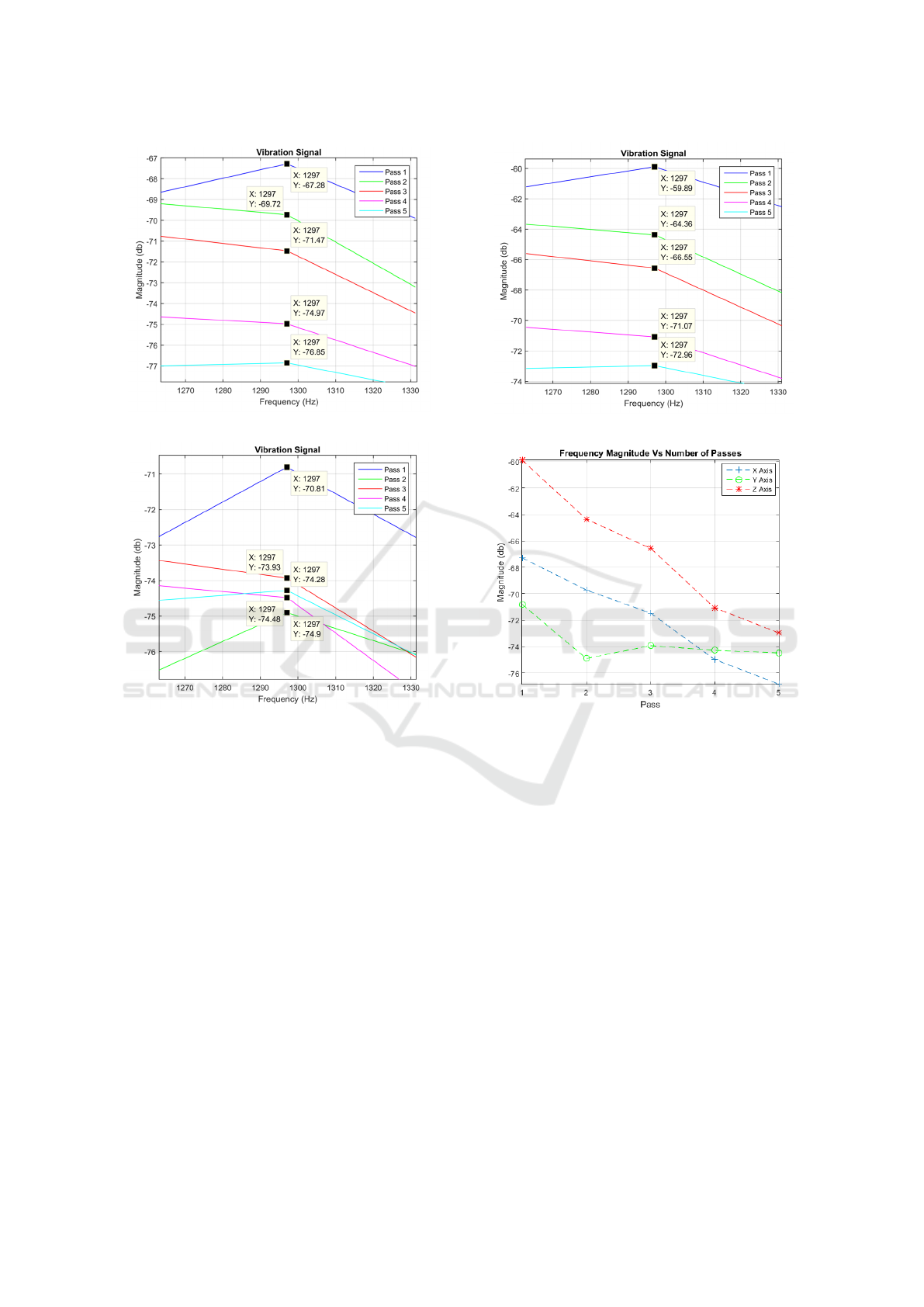
Figure 8: Vibration signature in X direction.
Figure 9: Vibration signature in Y direction.
plying the classification technique to other finishing
processes may not yield the same expected outcome.
This will be the focus of future research directions
of this work; to validate and set up a similar clas-
sification technique across other finishing processes
like polishing. Spectral analysis proved to be a vi-
able solution for performing this task and is seen as
a promising technique to be implemented in real-
time applications involving high sampling frequen-
cies. The advantage seen here is that, analyzing a
particular frequency component relieves the need of
bulk data processing as opposed to statistical meth-
ods wherein packets of data needs to be computed to
understand the co-relation between different statisti-
cal attributes with the number of passes completed.
Besides, the welch spectrum estimate showed signifi-
cant co-relation with the completed number of passes
as opposed to time-domain features like kurtosis and
skewness.
This research work was conducted primarily to
understand possible co-relation between sensor signal
Figure 10: Vibration signature in Z direction.
Figure 11: Signal Magnitude Vs Number of Passes.
features and the progress of the finishing process. The
co-relation observed will be integrated to the robotic
finishing software environment used for tool path pro-
gramming and will serve as a visual aid to shop floor
operators enabling them to monitor the progress of the
finishing process. In the next phase of the project, the
signature identified as a classifier will subsequently
be used as an input parameter for machine learning
algorithms. Additionally, a control strategy could be
deployed with a feedback loop in the robot control
system to dynamically adjust the process variables to
compensate for any unexpected behavior.
ACKNOWLEDGEMENTS
The authors would like to thank Mr. Arthur Wee and
Mr. Muhammad Izzat Roslan from Rolls-Royce Plc
Singapore for the support received in preparation of
this paper and the associated research work.
Event Classification from Sensor Data using Spectral Analysis in Robotic Finishing Processes
85

REFERENCES
C. Bisu, L. Olteanu, R. L. P. D. and Cahuc, O. (2013). Ex-
perimental approach on torsor dynamic analysis for
milling process monitoring and diagnosis. In Proce-
dia CIRP, vol. 12, pp. 73-78.
D. Dornfeld, P. Wright, M. H. and Vijayaraghavan, A.
(2009). Enabling manufacturing research through in-
teroperability. In ed.
G. Byrne, D. Dornfeld, I. I. G. K. W. K. and Teti, R. (1999).
Tool condition monitoring (tcm) the status of research
and industrial application, cirp annals - manufacturing
technology. In vol. 44, pp. 541-567, // 1995.
G. W. Fritz Klocke, D. V. (2008). Design approach for adap-
tive axial force control in gun drilling. In Mechanical
Systems and Control vol. 11,. .
Lee, Y. and Dornfeld, D. A. (1998). Application of open
architecture control system in precision machining. In
31st CIRP International Seminar on Manufacturing
Systems, CIRP, Berkeley, CA, pp. 436441. .
P. Stavropoulos, D. Chantzis, C. D. A. P. and Chryssolouris,
G. (2013). Monitoring and control of manufacturing
processes: A review. In Procedia CIRP, vol. 8, pp.
421-425.
Pritschow, G. and Kramer, C. (2005). Open system archi-
tecture for drives. In CIRP Annals - Manufacturing
Technology, vol. 54, pp. 375-378. .
R. Teti, K. Jemielniak, G. O. and Dornfeld, D. (2010). Ad-
vanced monitoring of machining operations. In CIRP
Annals - Manufacturing Technology, vol. 59, pp. 717-
739.
T. I. El-Wardany, D. G. and Elbestawi, M. A. (1996). Tool
condition monitoring in drilling using vibration sig-
nature analysis. In International Journal of Machine
Tools and Manufacture, vol. 36, pp. 687-711. .
Team, R. P. (2006). Guidelines to minimize manufacturing
induced anomalies in critical rotating parts. In ed.
SENSORNETS 2017 - 6th International Conference on Sensor Networks
86
