
SMART REIFIER: Model-Driven Development of Service-Oriented
SCADA Applications from Models of Sensor and Actuator Networks
Margaux Bosshardt, Cl
´
ementine Geslin and J
´
er
ˆ
ome Rocheteau
Institut Catholique d’Arts et M
´
etiers, 35 avenue du Champ de Manœuvres, Carquefou, France
Keywords:
Model-Driven Development, Domain-Specific Language, Service-Oriented Application, Supervisory Control
and Data Acquisition, Sensor and Actuator Network.
Abstract:
This paper aims at presenting SMART REIFIER a tool for designing networks of sensors and actuators and
for generating a set of web services for supervisory control and data acquisition. Such a code generation is
achieved by the means of model-driven engineering: a specific meta-model for sensor and actuator networks
is designed as well as a model-to-model mapping into a web service meta-model that enables source code
generation of JEE applications.
1 INTRODUCTION
The FUSE-IT project aims to design and implement
smart and secured building management systems for
safety-critical sites. Smart as electricity can be sup-
plied either from inside the building thanks to dif-
ferent types of generators or from the outside by the
grid. Secured as management systems should not
be misused in safety-critical contexts. During this
project, ICAM designs and implements a smart light-
ing demonstrator on its own site, a university of en-
gineering, with solar panels, batteries, light-emitting
diodes, presence and luminosity sensors, remote-
controlled switches and dimmers. Hence, such a
smart lighting system requires a management system
that fulfills the following features:
• operational for data acquisition and supervisory
control (SCADA),
• compatible with other SCADA applications e.g.
from project partners,
• available for third-party applications for visual-
ization, regulation, optimization, etc.
Moreover, this smart lighting implementation en-
countered some delays for selecting available com-
ponents according to their cost and features, for fix-
ing areas where they should be located, for stating the
accurate number of each type of component, for de-
signing a safe and independent electric network, for
determining communication networks and technolo-
gies, etc.
This leads us to adopt a model-driven approach
with distinct models from their implementations and
automatic code generation. In fact, model-driven
engineering of such a sensor and actuator network
(SAN) makes it possible to update the smart lighting
design as often as it is mandatory with the less mod-
ifications possible regardless of its implementation.
The specific component implementations of gener-
ated SCADA applications only corresponds to com-
munication modules of each type of sensors and ac-
tuators that compose such a network. Such a model-
driven engineering then allows us to focus more on
SAN design than on SCADA development. The most
important added-value consists in enabling SCADA
application development according to a top-down ap-
proach alongside a co-design of its sensor and actu-
ator network instead of a bottom-up approach that
is posterior its network and actuator network design
which is mostly and currently the case; with a better
support for design checking, component reuse, etc.
This paper is organized as follows: Section 2
presents the smart lighting demonstrator design at
ICAM. Section 3 defines a domain-specific language
for sensor and actuator networks and formalizes the
previous study case. Such models will be embedded
into web services which meta-model is presented by
section 4 thanks to a model-to-model transformation
detailed in section 5. This meta-model of web ser-
vices makes possible to generate SCADA application
source code as section 6 explains. Related work is
then investigated in section 7 in order to prove the
novelty and the relevance of our approach.
Rocheteau J., Geslin C. and Bosshardt M.
SMART REIFIER: Model-Driven Development of Service-Oriented SCADA Applications from Models of Sensor and Actuator Networks.
DOI: 10.5220/0006198201250136
In Proceedings of the 5th International Conference on Model-Driven Engineering and Software Development (MODELSWARD 2017), pages 125-136
ISBN: 978-989-758-210-3
Copyright
c
2017 by SCITEPRESS – Science and Technology Publications, Lda. All rights reserved
125
2 SMART LIGHTING
DEMONSTRATOR
This section aims at introducing specifications of the
smart lighting demonstrator at ICAM: a network com-
posed of sensors and actuators set up to regulate the
light level in offices and to monitor its energy con-
sumption. It requested a long time to implement this
design and, moreover, the latter could change accord-
ing to different parameters such as component costs,
component availability, etc. This design variability
has motivated the model-driven approach described
in section 3. The entire system, including power
sources, will not be described. However, a specific fo-
cus will be made on the lighting system as a running
example. This system should comply to the European
norm EN 12464-1 that requires a minimum light level
for working zones and their surrounding area. 500
LUX are needed in working areas, but in other areas
of the room a minimum of 300 LUX need to be main-
tain.
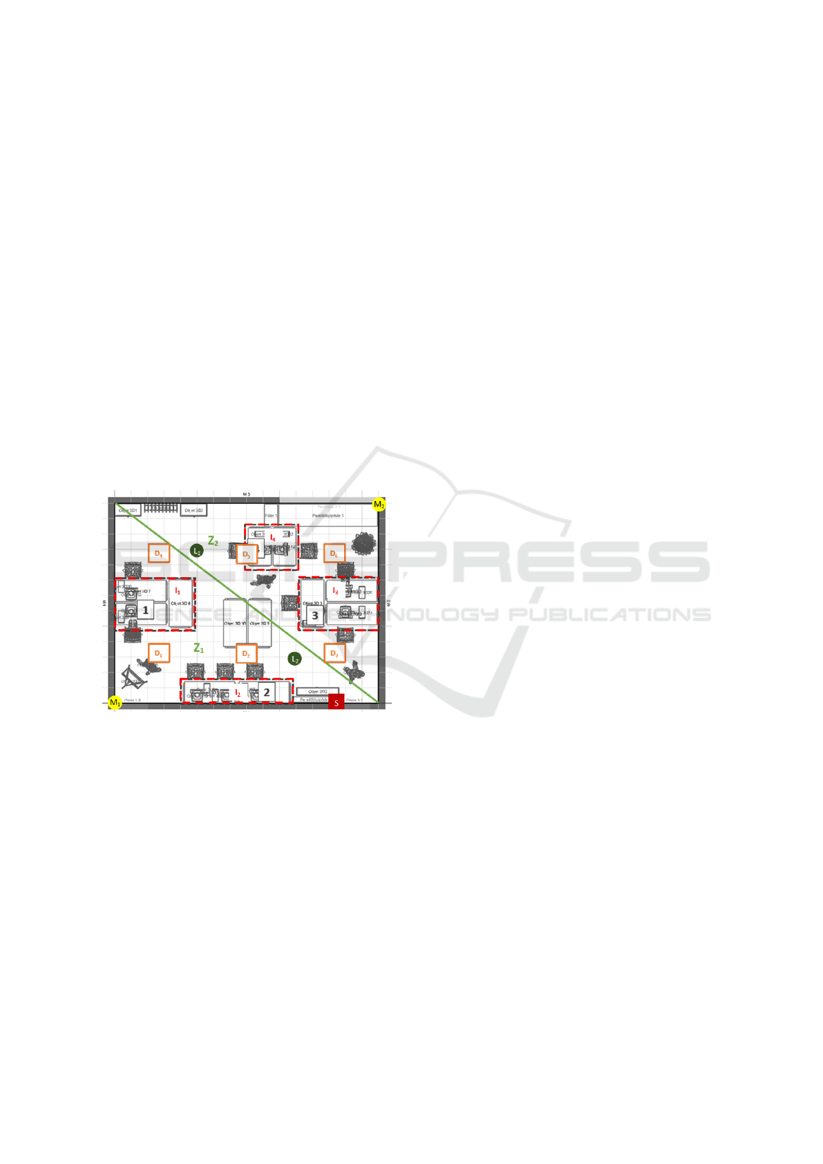
Figure 1: Smart Lighting Supervisory Demonstrator.
As stated above, ICAM designs and implements a
smart lighting demonstrator in its own building based
in Nantes. Solar panels and batteries are used to light
up a 22.84 square meters room, composed of 4 work-
ing islets. Thus, the demonstrator is composed of
three main parts which are (a) the photovoltaic panels
located on the roof, (b) an energy part equipped with
electric storage batteries, electric inverters, power-
meters, computers hosting SCADA applications (c)
and the lighting system itself located in the IT labora-
tory. This lighting system is illustrated by figure 1. It
is composed of these physical or logical items:
• 2 zones Z
1
and Z
2
composing an upper zone.
• 2 motion sensors M
1
and M
2
associated to their
corresponding zone which report at a fixed rate
whether somebody is detected.
• 2 light sensors L
1
and L
2
that provide the lumi-
nosity value when they are requested to.
• 6 light-emitting diodes (LED), each one equipped
with a remote-controlled dimmer D
1
, D
2
, D
3
, D
4
,
D
5
and D
6
that settle the light level of their corre-
sponding LED.
• 4 islets or working zones I
1
, I
2
, I
3
and I
4
that are
dispatched between the 2 zones Z
1
and Z
2
.
• 1 switched S that allows users to to switch on or
to switch off lights.
Light level of each islet can automatically be com-
puted according to the luminosity values of the light
sensors L
1
and L
2
.
In addition, the lighting system should perform as
follows: It has to adjust to every islet light levels ac-
cording to the luminosity values retrieved from the
light sensors when somebody is detected in one of the
two zones or the switch S is on. It has to switch off
LED when nobody is detected in any zone and the
switch S is off. It has to toggle the switch S if nobody
is detected in any zone after a certain time.
3 SENSOR AND ACTUATOR
NETWORK METAMODEL
These previous specifications of the smart lighting
demonstrator leads us to identify required features
of the SAN meta-model. In fact, such a meta-model
should make it possible to:
Locate Sensors and Actuators in a Zone. For ex-
ample, the motion sensor M
1
belonging to the zone
Z
1
.
Locate a Zone Inside another Zone. The zone Z
1
belonging to the zone that corresponds to the entire
office.
Distinguish Models and Devices. In fact, the two
motion sensor devices will probably be the same
model but located in different zones.
Define Computations. Simple ones like “receive the
motion sensor M
1
message” or more complex ones
like “adjust light levels”.
Define Parametric Computations. In fact, the two
computations “receive the motion sensor M
1
mes-
sage” and “receive the motion sensor M
2
message”
corresponding to a single computation “receive the
motion sensor X message” applied to different param-
eters M
1
and M
2
.
Trigger Computations on Events. For instance, it
corresponds to adjust the light levels when somebody
is detected in a zone.
MODELSWARD 2017 - 5th International Conference on Model-Driven Engineering and Software Development
126

network = (name:name,instruments:instrument*,places:place*,processes:process*)
instrument = (name:name,mode:mode,component:component,attribute:variable*)
mode ::= sensor | actuator
place = (name:name,place:place?,instances:instance*)
instance = (name:name,instrument:instrument,parameters:parameter*)
process = (component:component,triggers:trigger+)
trigger ::= event | loop | task | user
event = (instance:instance)
loop = (delay:long)
task = (resource:resource)
user = (path:name)
Figure 2: Meta-Model of Sensor and Actuator Networks.
Trigger Computations at Fixed-rate. For instance,
it corresponds to toggle the switch S if nobody is de-
tected after a while.
These SAN requirements leads us to design the
figure 2 meta-model by the means of a formal gram-
mar. The main syntactic category network enables
to specify SAN models as a list of instruments (sen-
sor and actuator models), places (zones) and pro-
cesses (triggered computations). Syntactic categories:
name, resource, component, variable and param-
eter are drawn out from figure 3 meta-model of
component-based web services and will fully be ex-
plained in section 4. Components are parametric
ones: they can be defined either as abstract com-
ponents that are implemented by a Java class or as
compound components that are composed of con-
crete components. Concrete components correspond
to components specialized by some parameter values.
Instruments are defined by the means of the so-
called category instrument. They are defined by their
mode i.e. sensor or actuator. They are also defined by
their component which corresponds to the communi-
cating unit implementation that retrieves or receives
data from this instrument. Moreover, instrument data
structure is defined by a list of attributes; the latter
made of a name and a data type.
Areas or zones are defined by the means of the
category place. They can be linked to an upper place
by the feature called place and they are defined by
a list of instances. Instances correspond to sensor or
actuator devices. In fact, instances are related to an
instrument and can be applied to a list of parameters.
The latter should exactly match the instrument com-
ponent parameters.
Finally, processes are defined by the means of the
category process which extends the category of com-
ponent with a feature trigger at least. This feature
refers to the so-called category trigger and is defined
either (1) as an event on interactions with a specified
instance or (2) as a loop at a fixed-rate specified by a
feature delay or (3) as a background task specified by
a REIFIER’s resource that is launched at the SCADA
application deployment or (4) as a specific service
launched by SCADA application users given a path.
The meta-model of SAN is an extension of that of
web services. As the model-to-model transformation
maps SAN models to web service ones (see section 5),
the SAN meta-model then consists of an extension of
that of web services. It can be seen as syntactic sugar.
However, it allows to focus on business modelling
mainly and to hide technical implementations. It then
provides a flexible abstraction layer with full sup-
port. Full support as a compliant SCADA application
is generated from SAN models. Flexibility is ensure
because this framework allows designers to focus on
describing networks of sensors and actuators only and
it allows developers to focus on customized comput-
ing units only. For instance, figure 1 shows the smart
lighting demonstrator model at ICAM in XML format.
This model is composed of three parts. The first part
consists of listing the instruments i.e. the sensor or
actuator models. Every instruments specify one at-
tribute only which correspond to the data structure re-
quired or emitted by sensors or actuators. Every in-
struments specify one component as required which
is related to the Java qualified name of the component
that has to retrieve or provide data respectively from
or to sensors and actuators. In addition, some instru-
ments specify abstract parameters that will be useful
in order to specialize their instances. The second part
of the model consists of listing the places with their
associated instances. i.e. the physical devices whose
models are declared within the instrument part of the
model. Some instances define values to parameters
declared by their instruments. The third part of the
model consists of listing the processes that have to be
launched either while interacting with instances or at
fixed-rate as specified by their inner trigger tag. Com-
ponent attributes of these process tags corresponds to
the Java qualified names of components formalized
by an underlying model of web services as section 6
explains whose meta-model is described in section 4.
SMART REIFIER: Model-Driven Development of Service-Oriented SCADA Applications from Models of Sensor and Actuator Networks
127

Listing 1: Smart Lighting Demonstrator Model.
1 <san:network name=” f r . icam . f u s e i t ”>
<san:instrument name= ” m otion ” mode= ” sensor ” component= ” f r . icam . f u s e i t . d r i v e r s . MotionSensor ”>
3 <s a n: a t t ri bu t e name= ” presence ” typ e = ” boolean ” />
</ san:instrument>
5 <san:instrument name= ” l u m i n o s i t y ” mode= ” sensor ” component= ” f r . icam . f u s e i t . d r i v e r s . LuxSensor ”>
<san:parameter name= ” u r i ” type = ” u r i ” />
7 <s a n: a t t ri bu t e name= ” lu x ” type= ” i n t e g e r ” />
</ san:instrument>
9 <san:instrument name= ” dimmer ” mode= ” a c t u a t o r ” component= ” f r . icam . f u s e i t . d r i v e r s . Dimmer ”>
<san:parameter name= ” u r i ” type = ” u r i ” />
11 <s a n: a t t ri bu t e name= ” l e v e l ” ty p e= ” f l o a t ” />
</ san:instrument>
13 <san:instrument name= ” swi tch ” mode= ” sensor ” component= ” f r . icam . f u s e i t . d r i v e r s . Switch ”>
<s a n: a t t ri bu t e name= ” st a t e ” type= ” boolean ” />
15 </ san:instrument>
<san:place name= ” c115 ”>
17 <san: inst ance name= ” dimmer−1” in s tr um e nt = ” dimmer ”>
<san:parameter name= ” u r i ” type = ” u r i ” value = ” h t t p : / / 1 7 2 .2 1. 22 0. 12 ” />
19 </ sa n:instance>
<san: inst ance name= ” dimmer−2” in s tr um e nt = ” dimmer ”>
21 <san:parameter name= ” u r i ” type = ” u r i ” value = ” h t t p : / / 1 7 2 .2 1. 22 0. 13 ” />
</ sa n:instance>
23 <san: inst ance name= ” dimmer−3” in s tr um e nt = ” dimmer ”>
<san:parameter name= ” u r i ” type = ” u r i ” value = ” h t t p : / / 1 7 2 .2 1. 22 0. 14 ” />
25 </ sa n:instance>
<san: inst ance name= ” dimmer−4” in s tr um e nt = ” dimmer ”>
27 <san:parameter name= ” u r i ” type = ” u r i ” value = ” h t t p : / / 1 7 2 . 2 1. 22 0. 15 ” />
</ sa n:instance>
29 <san: inst ance name= ” dimmer−5” in s tr um e nt = ” dimmer ”>
<san:parameter name= ” u r i ” type = ” u r i ” value = ” h t t p : / / 1 7 2 .2 1. 22 0. 16 ” />
31 </ sa n:instance>
<san: instance name= ” dimmer−6” in s tr um e nt = ” dimmer ”>
33 <san:parameter name= ” u r i ” type = ” u r i ” value = ” h t t p : / / 1 7 2 . 2 1. 22 0. 17 ” />
</ sa n:instance>
35 <san: inst ance name= ” switch −1” in s tr ume nt = ” sw i tch ”></ sa n:instance>
</ san:place>
37 <san:place name= ” c115a ” place= ” c115 ”>
<san: instance name= ” motion−a ” in s tr um e nt = ” motion ”></ san:instance>
39 <san: inst ance name= ” l um in os it y−a ” i ns t ru m en t = ” l u m i n o s i t y ”>
<san:parameter name= ” u r i ” type = ” u r i ” value = ” h t t p : / / 1 7 2 .2 1. 22 0. 10 ” />
41 </ sa n:instance>
</ san:place>
43 <san:place name= ” c115b ” place= ” c115 ”>
<san: instance name= ” motion−b ” in s tr um e nt = ” motion ”></ san:instance>
45 <san: inst ance name= ” l um in os it y−b ” i ns t ru m en t = ” l u m i n o s i t y ”>
<san:parameter name= ” u r i ” type = ” u r i ” value = ” h t t p : / / 1 7 2 .2 1. 22 0. 11 ” />
47 </ sa n:instance>
</ san:place>
49 <san:process component= ” f r . icam . f u s e i t . components . DimmerAdjust ”>
<san:event ins t an c e= ” motion−a ” />
51 </ san:process>
<san:process component= ” f r . icam . f u s e i t . components . DimmerAdjust ”>
53 <san:event ins t an c e= ” motion−b ” />
</ san:process>
55 <san:process component= ” f r . icam . f u s e i t . components . SwitchWatch ”>
<san:loop d e l a y = ” 30 ” />
57 </ san:process>
</ san:network>
MODELSWARD 2017 - 5th International Conference on Model-Driven Engineering and Software Development
128

4 WEB SERVICE METAMODEL
The meta-model of component-based and service-
oriented applications has been presented in (Ro-
cheteau and Sferruzza, 2016). It is powered by
a tool called REIFIER that generates JEE appli-
cations from compliant models of web services.
Hence the name of this prototype built on top of
REIFIER generates services-oriented SCADA applica-
tions: SMART REIFIER.
The complete meta-model of web services is de-
fined by the grammar in figure 3 and by the claass
diagram in figure 6. Only its relevant features with
respect to the SAN meta-model are presented. A
model of web service is defined by three main sub-
models: data model, component model and service
model. Data model encompasses type, aspect and en-
tity categories. Types correspond to basic data types
in Java, aspects are abstract data types that will be
mapped to Java interfaces whereas entities correspond
to data structures and will be mapped to Java classes.
Component model corresponds to parametric compo-
nents. And service model enumerates entry points of
applications where services can be seen as specializa-
tions of components to data types. In fact, parametric
components can be instantiated and applied to param-
eter values and those values can be data types like en-
tities. Moreover, web service meta-model allows to
specify application resources that can be available to
components. These resources can be used to sched-
ule background tasks at fixed rate and will be used for
mapping the last kind of processes in the SAN meta-
model.
5 MODEL TRANSFORMATION
As JEE applications can be automatically generated
from models of web services thanks to the REIFIER
tool, the code generation of SCADA applications from
SAN models will then consists of a model-to-model
transformation by the means of the SMART REIFIER
tool. Generated SCADA applications will therefore be
service-oriented ones.
The model transformation is twofold: On the one
hand, it consists of a fixed model of entities, resources
and components that are used to embed elements of
the SAN meta-model such as instruments and places
as well as resources required for data persistence
management. On the other hand, it consists of a vari-
able model of aspects, entities, instances, components
and services drawn out from the content of SAN mod-
els.
Fixed Transformation. The fixed part of target
models is composed of two entities. The first en-
tity Place owns two properties that correspond to its
name and its upper place. The second entity Instru-
ment owns three properties: its name, its place and
its type i.e. sensor or actuator. These two entities will
be stored into a database and instances of such enti-
ties will be introduced from SAN models. Another en-
tity TimeSpan is added into the target model with two
properties started and stopped which types are time-
stamps. This entity represents a span of time that will
be used as the data structure of request messages that
aims at retrieving data of instrument instances. How-
ever, this entity TimeSpan will not be stored into a
database. In addition, the fixed part of target models
is composed of several abstract components which are
provided by Java libraries. The first two components
concern data acquisition by the SCADA application
from instrument instances: the first one called TimeS-
tamper sets the time-stamp of object data, the sec-
ond one called HibernateCreator inserts object data
into a database. The last six components concern
data retrieving by the users from the SCADA appli-
cation: Two components called JsonDeserializer and
JsonSerializer in charge of, respectively, decoding or
coding messages in JSON format are introduced into
target models. A component called FeatureGrabber
able to extract data features is introduced into target
models in order to extract started and stopped val-
ues from TimeSpan objects. Three components pro-
vided by a REIFIER component library for Hibernate
are also introduced into target models. The first one
called HibernateCriteriaProvider prepares SQL state-
ments from a given entity. The second one called Hi-
bernateTimeSpanFilter inserts SQL restrictions from
the grabbed started and stopped features from TimeS-
pan objects. The third one called HibernateListRe-
triever executes SQL statements and provides data
lists. Finally, the fixed part of target models is com-
posed of several services that consists of SCADA ap-
plication main functionalities:
• a GET method service retrieving the list of places,
• a POST method service retrieving the sub-places
of a given place,
• a POST method service retrieving the instrument
instances of a given place.
These services allows to navigate through out sensor
and actuator networks in order to access their data ob-
tained by the means of services
Variable Transformation. As for the variable part
of target models, transformation is driven either by
instrument, or by place, or by instance, or by process.
SMART REIFIER: Model-Driven Development of Service-Oriented SCADA Applications from Models of Sensor and Actuator Networks
129

model = (name:string, entities:entity*,instances:instance*, . . .
. . ., resources:resource*,components:component*,services:service*)
service component[name:string,path:name,method:method,request:message,response:message]
message = (content-type:string,content-encoding:string,headers:string*,type:type)
method ::= get | post | put | delete | head | options | trace | connect
component ::= atomic | composite
atomic = (name:string,inputs:variable*,outputs:variable*,parameters:variable*)
composite abstract[components:parametrized*,processing:processing]
processing ::= sequence | failover
parametrized = (component:component,parameters:parameter*)
resource = (name:string,parameters:parameter*)
parameter variable[term:term]
attribute variable[required:boolean,reference:parameter]
term ::= variable | constant
variable = (name:string,type:type)
constant = (type:type,value:object)
entity type[name:string,stored:boolean,entity:entity?,aspects:aspect*,properties:property*]
aspect type[name:string,features:property*]
property = (name:string,type:type,required:boolean)
type ::= string | boolean | integer | float | date | class | aspect | entity
Figure 3: Meta-Model of Web Services.
Instrument transformation consist of introducing
an aspect defined by the name of this instrument and
which features are provided by the instrument at-
tributes. An additional feature issued is added to
this aspect in order to time-stamp any received data.
This aspect corresponds to the common data structure
among every instances of this instrument. Finally, it
consists of introducing a component whose signature
is composed of the specified instrument parameters
and three other parameters: type, input and output.
The first one type corresponds to the data type this
component handles. The last two correspond to the
name of, respectively, the component input and the
component output. These inputs and outputs should
verify the type provided by the value of the type pa-
rameter. Moreover, this type should also comply to
the aspect generated from this instrument transforma-
tion.
Whereas, place transformation merely consist of
introducing instances of the entity Place with the ap-
propriate features, instance transformation consist of
introducing:
• an instance of the entity Instrument with the ap-
propriate properties i.e. its type, name and place;
• an entity that complies the instrument aspect i.e.
with properties that correspond to the instrument
aspect features which instances are stored into a
dedicated table of a database;
• a compound component composed of the instru-
ment component that provides instrument data,
the TimeStamper component, the HibernateCre-
ator component;
• a service that wraps the previous compound com-
ponent;
• a service that receives a message that corresponds
to a TimeSpan object data and that provides the
list of instances from the dedicated database table
of the instrument entity for the requested span of
time.
Finally, process transformation consists either of in-
troducing the process component at the end of the
compound component transformed from the instance
if this process is triggered on an event, or of introduc-
ing a resource that wraps the same compound compo-
nent within a Java thread if this process is triggered at
fixed-rate.
6 CODE GENERATION
Code generation of SCADA applications is ensured by
the SMART REIFIER tool. The latter is a set of mod-
ules for the REIFIER tool which is a Maven plugin that
generates JEE applications from models of web ser-
vices. The SMART REIFIER code generation behaves
as follows:
1. it compiles a web service model from a XML file
src/main/reifier/model.xml;
2. it compiles a SAN model from a XML file
src/main/reifier/network.xml;
3. it tranforms the previous SAN model into a web
service model according to the rules explained in
section 5 and merges with the first web service
model;
MODELSWARD 2017 - 5th International Conference on Model-Driven Engineering and Software Development
130
REIFIER Core Functionalities
SMART REIFIER Modules
REIFIER Libraries
REIFIER other Modules
WS Checkers
model.xml
network.xml
WS
SAN
WS
WS XML Reader
SAN XML Reader
M2M Transformer
JEE Application Generator
Hibernate Mapping Generator
WS
JEE SCADA Application
Commons Library Hibernate Library
3
rd
Party Libraries
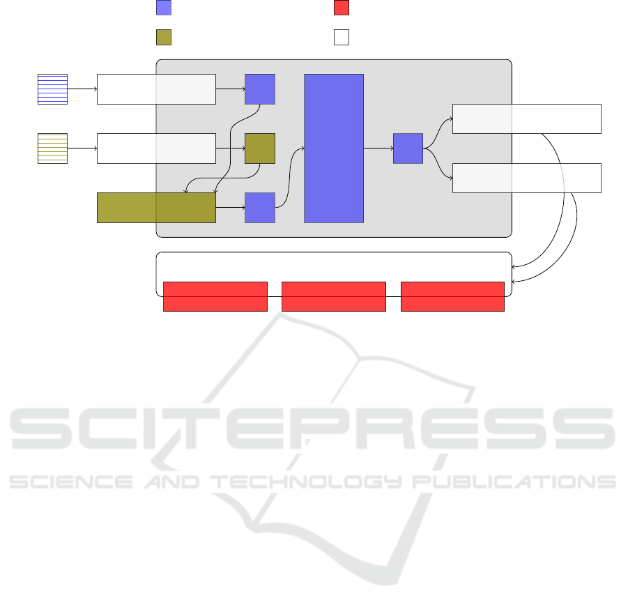
Figure 4: Architecture of the REIFIER tool and the SMART REIFIER modules.
4. it then applies REIFIER for model verification and
code generation on the merged web service model
in order to obtain the service-oriented SCADA ap-
plication.
This code generation is illustrated by figure 4 where
SMART REIFIER elements correspond to REIFIER
modules. Firslty, figure 4 points out that the code
generation relies on other modules that can be used
in other contexts. Secondly, it points out that the gen-
erated SCADA application depends on Java libraries.
Finally, it illustrates that the REIFIER tool merely ver-
ifies the consistency of web service models.
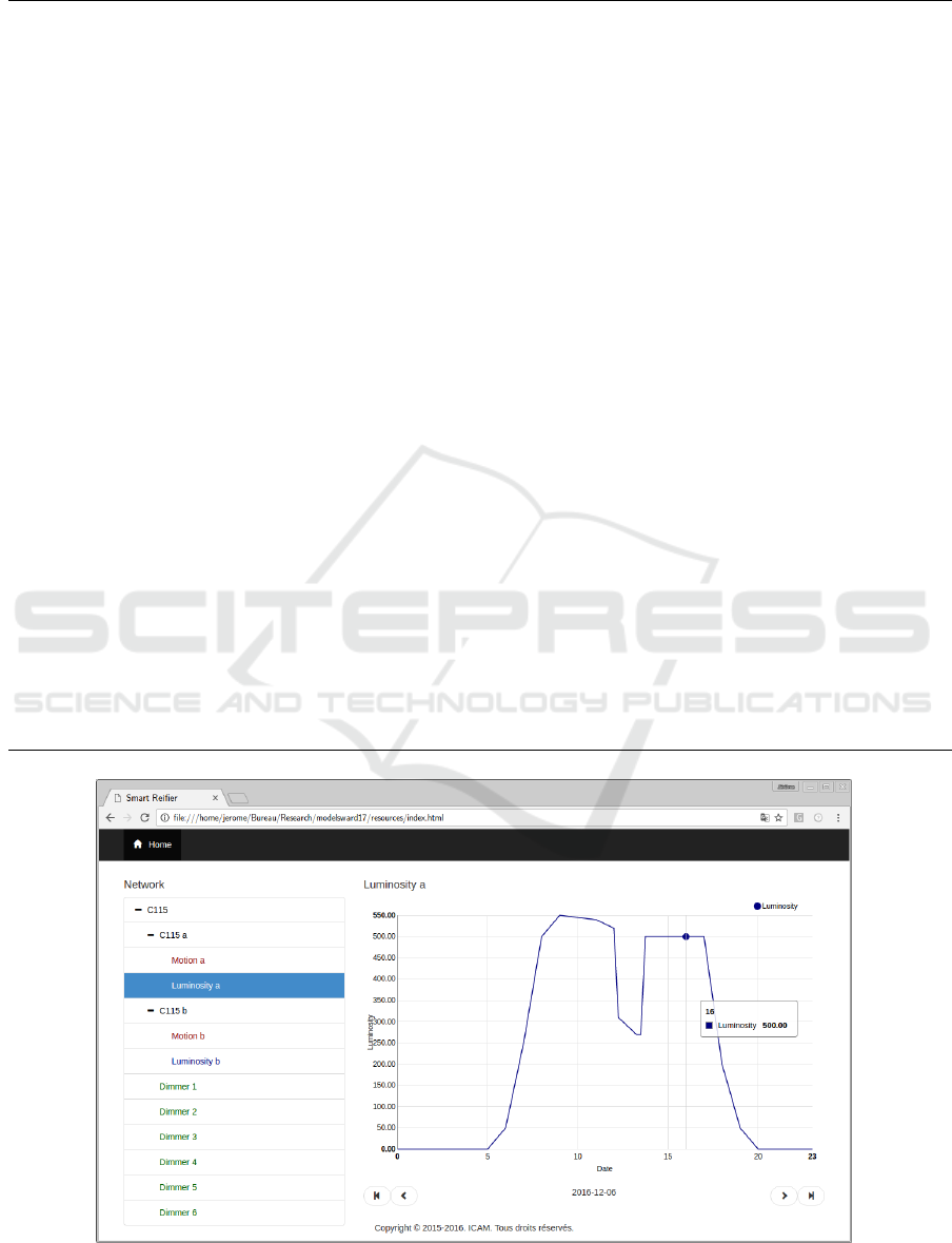
The code generation also provides a client-side
application based on HTML, Bootstrap CSS and An-
gularJS technologies as figure 5 shows. This client-
side application is unique as the code generation com-
plies to the rules explained in section 5 and offers
the three services of the fixed transformation that help
to navigate through out sensor and actuator networks
uniformly.
SCADA Application. The generated JEE applica-
tion is a basic SCADA application. In fact, data ac-
quisition is ensured as the generated JEE application
is able to store sensor and actuator data into a database
by the means of the transformed instance compound
component and the transformed service that wraps the
previous component. Moreover, it is able to provide
these data by chunks of time intervals by the means of
the other transformed service. Such a service enables
supervisory control as SCADA applications users then
can visualize data and, if needed, then launch some
operations by the means of processes whose trigger
is a user one. Such controls can be automatized by
processes either triggered on instance communication
or at fixed-rate. The code generation powered by the
REIFIER tool also provides trendy SCADA application
features such as service-oriented application, generic
client-side application interfaces as figure 5, relational
database persistence as well as NOSQL management
for big data processing. Nevertheless, it doesn’t al-
low to manage SQL and NOSQL databases alongside.
However, the generated JEE application is not a com-
plete SCADA application in the sense that it lacks of
auxiliary functionalities. Users, roles and grants are
not taken into account. Indeed, this approach is de-
voted to one sort of users: administrators of sensor
and actuator networks. That should be required in or-
der to adapt SAN views according to user roles.
SCADA Engineering. The code generation carries
out most of the SCADA application components. It
carries out application architecture and logic as well.
This makes then possible to focus more on model
design than application development. Development
merely consists either in communication modules
with sensors or actuators or in control operations for
specific application behaviour. For example, listing 2
illustrates the Java implementation of a HTTP-based
sensor communication component that retrieves data
from a luminosity sensors. It’s a pull communication
component. In fact, this sensor component implemen-
tation rely on a underlying data type, here hidden,
called LuxSensorMeasurement. It consists of an in-
SMART REIFIER: Model-Driven Development of Service-Oriented SCADA Applications from Models of Sensor and Actuator Networks
131

Listing 2: The atomic component LuxSensor.
@Parameter (name= ” u r i ” , typ e = ” u r i ” ) p r iva t e URI u r i ;
2 @Parameter (name= ” typ e ” , t y p e = ” type ” ) p r i va t e St r i n g type ;
@Parameter (name= ” data ” , type= ” s t r i n g ” ) pri v ate S t r i n g data ;
4
publi c void doProcess ( Ht t pSer v let R eque s t request , HttpServletResponse response ) throws S e rv le t Ex ce p ti on {
6 I n t e g e r l u x = t h i s . getLux ( t h i s . u r i ) ;
@Output (name= ” ${data}” , ty p e =” ${type} ” )
8 LuxSensorMeasurement measurement = new LuxSensorMeasurement ( ) ;
measurement . set L ux ( l u x ) ;
10 re quest . s e t A t t r i b u t e ( t hi s . data , measurement ) ;
}
12
pr i va t e I n te g e r getLux ( URI u r i ) throws E x c ep ti o n {
14 Cl os ea bl eH tt p C l i e n t c l i e n t = H t t p C l i e n t s . c r e a t eD ef a u l t ( ) ;
t r y {
16 HttpG e t re quest = new Ht t pGet ( u r i ) ;
CloseableHttpResponse response = c l i e n t . execute ( req u e st ) ;
18 t r y {
InputStr e a m i np u t = response . g e t E n t i t y ( ) . getContent ( ) ;
20 S tr i n g s t r i n g = I O U t i l s . t o S t r i n g ( i n put , UTF8 ) ;
return I n t eg e r . valueOf ( s t r i n g ) ;
22 } f i n a l l y {
response . cl ose ( ) ;
24 }
} f i n a l l y {
26 c l i e n t . c l ose ( ) ;
}
28 }
teger feature called lux that is directly drawn out from
the sensor specification of the figure 1. Moreover, this
data type is enriched by another feature called issued
that corresponds to the time at which such data are
retrieved. The latter will be provided by the TimeS-
tamper component which is inserted just after such
a communication component. This component im-
plementation LuxSensor define two common param-
eters: a first type parameter called type – useful for
the component formal verification from the REIFIER
tool – and a second string parameter called data that
corresponds to that attribute name of measurements
Moreover, the LuxSensor component owns a third pa-
rameter called uri that is defined within its different
instances in the model of the figure 1 and that stands
for sensor instance IP addresses. This atomic com-
ponent complies the Component interface and can be
embedded into a composite component. In fact, the
SCADA application code geneartion of ICAM smart
lighting demonstrator provides a composite compo-
nent called LuminosityAComponent that corresponds
to the model instance luminosity-a of the place c115-
a and that embeds the atomic component LuxSensor.
Listing 3 illustrates how such atomic components are
compound into a composite component.
Other types of communication can be handled:
the pull and pooling communications. Pull commu-
nication component merely consists in retrieving data
from sensors and in populating an instance of the data
structure associated to the sensor. Pooling communi-
cation consists, on the one hand, in a push-like com-
munication component and, on the other hand, in a
resource that initializes the connection with the sen-
sor. Such resources are launched as background tasks
when SCADA applications are deployed.
The model-driven engineering of SCADA applica-
tions from SAN models then makes possible to fo-
cus more on design as it provides a strong support
by the means of the JEE application code generation.
Moreover, it provides a support for formal verifica-
tion thanks to the REIFIER tool. However, integration
of heterogeneous components still remains flexible as
different communication protocols can be managed.
7 RELATED WORK
Applications of model-driven engineering to SCADA
applications or sensor and actuators networks are
twofold: Firstly, it has been used for SAN modelling.
Secondly, model-driven engineering has been used
for testing SCADA applications. These two domains
are investigated before the relevance of our approach
is discussed.
MODELSWARD 2017 - 5th International Conference on Model-Driven Engineering and Software Development
132
Listing 3: The composite component LuxSensor.
@Parameter (name= ” u r i ” , typ e = ” u r i ” ) p r iva t e URI u r i ;
2 @Parameter (name= ” typ e ” , t y p e = ” type ” ) p r i va t e St r i n g type ;
@Parameter (name= ” data ” , type= ” s t r i n g ” ) pri v ate S t r i n g data ;
4
pr i va t e LuxSensor aLuxSensor1 ;
6 pr iv a t e TimeStamper aTimeStamper2 ;
pr i va t e Hi b ern a teC r eat o r a H i bernat e C reator 3 ;
8
publi c void setUp ( S e rv le t Co nt e xt cont e x t , S er vl et Co nf ig c on f i g ) throws S e r v le t E x ce p t i on {
10 aLuxSensor1 = new LuxSensor ( ) ;
aLuxSensor1 . s e t U r i ( th i s . u r i ) ;
12 aLuxSensor1 . setType ( t hi s . type ) ;
aLuxSensor1 . se t Data ( t hi s . data ) ;
14 aTimeStamper2 = new TimeStamper ( ) ;
aTimeStamper2 . setType ( t h is . type ) ;
16 aTimeStamper2 . setName ( ” iss u e d ” ) ;
aHib e r nateCr e a tor3 = new Hib e rnat eCre a tor ( ) ;
18 aH iberna t e Creator 3 . s etH i be r na t e ( ” h i be r n a te ” ) ;
aHib e r nateCr e a tor3 . setType ( t hi s . ty p e ) ;
20 aLuxSensor1 . setUp ( cont e xt , c o n f ig ) ;
aTimeStamper2 . setUp ( co ntext , c on fi g ) ;
22 aH iberna t e Creator 2 . setUp ( cont e x t , c o n f i g ) ;
}
24
publi c void doProcess ( Ht t pSer v let R eque s t request , HttpServletResponse response ) throws S e rv le t Ex ce p ti on {
26 aLuxSensor1 . doProcess ( r e quest , response ) ;
aTimeStamper2 . doProcess ( r e q uest , response ) ;
28 aH iberna t e Creator 3 . doProcess ( re q u est , response ) ;
}
30
publi c void tearDown ( ) {
32 aLuxSensor1 . tearDown ( ) ;
aTimeStamper2 . tearDown ( ) ;
34 aH iberna t e Creator 3 . tearDown ( ) ;
}
Figure 5: Screenshot of the Smart Lighting Demonstrator SCADA Application.
SMART REIFIER: Model-Driven Development of Service-Oriented SCADA Applications from Models of Sensor and Actuator Networks
133

Design. The application of model-driven engineer-
ing to sensor and actuator networks has already been
investigated and this approach share several features
with those found in the scientific literature (Rodrigues
et al., 2011; Priego et al., 2016). In fact, most of the
experiments about SAN modelling present different
solutions for assisting their design and development
as noticed in (Rowe et al., 2010; Kowal et al., 2014).
In (Vidal et al., 2015), MindCPS solution is a solution
that aims at facilitating SAN development. To do so,
the idea is to provide modelling primitives for explic-
itly specifying the autonomic behaviour of the system
and to model transformations for automatically gen-
erating part of the code. The main advantages of this
automated code generation is to allow a rapid config-
uration and development, even for a newcomer user.
Adopting a model-driven development approach fa-
cilitate the developing of SAN applications and pro-
mote a clear and synergetic separation between the
specification of the requirements at the application
level and such specification in a given sensor plat-
form (Rodrigues et al., 2013). Models — statistical
or otherwise -– are used for describing, simplifying
or abstracting various components of sensor data ac-
quisition and management (Sathe et al., 2013). The
best way to ease developer job seems to model sepa-
rately the software architecture of sensor and actuator
networks, the low-level hardware specification of the
SAN nodes and the physical environment where nodes
are deployed in (Doddapaneni et al., 2012). This
separation of concerns is needed since hardware and
software aspects are locked and tied down to specific
types of nodes, hampering the possibility of reuse
across projects and organizations.
Several articles tackle the use of domain-specific
languages for the development of sensor and actua-
tor networks. LWiSSy (Dantas et al., 2013) has been
promoted as a domain language that considers three
levels of programming granularity which may have
distinct characteristics regarding the used platform or
data processing. The idea is to divide the responsibil-
ity in dividing the expert skills by requiring from them
only their specific knowledge. Thus, one large model
is difficult to visualize, maintain, and analyze taking
into account evolution. Different views onto the fea-
ture model or the combination of two or more features
models, one for each domain, may solve some of the
existing problems.
Testing. The step of verification and validation of
distributed systems is another considerable challenge
(Yang et al., 2014). In (S
¨
uß et al., 2008) approach
to the problem of testing a SCADA thanks to Mod-
elica, an object-oriented mathematical modelling lan-
guage for component-oriented modelling of complex
physical systems. It is an open standard and imple-
mentation, and provides a rendering of its input lan-
guage in Ecore, the metalanguage of the Eclipse Mod-
eling Framework (EMF). This tooling allows a test
engineer to model all aspects of a SCADA test within
one workbench and enjoy full traceability between the
proprietary test model, and its surrounding environ-
ment simulation.
ITEA 2 projects IMPONET and NEMO & CODED,
focused on supporting complex and advanced re-
quirements of smart grids, specifically supporting en-
hanced efficiency through sensing and metering tech-
nologies, as well as automated control and manage-
ment techniques based on energy availability and the
optimization of power demand (Vidal et al., 2015).
Discussion. The starting point of this work was to
provide a scalable modelling approach covering vari-
ability and evolution of the smart lighting system at
ICAM. Indeed, the model-driven development allows
us to apply this approach to every other networks
of sensors and actuators that could be modelled ac-
cording to the SAN meta-model of figure 2. How-
ever, it has not been investigated to which extend
this approach can be applied to: internet of things,
edge computing, etc. In addition, several works have
pointed out the close relationship between applica-
tion requirements and SAN performance, and demon-
strated that application-specific optimization can in-
crease overall system performance, mainly regarding
the energy consumption. (Yang et al., 2014) points
out an inherent intertwining between modelling in the
control sense and model-driven software engineering.
The major drawback of this approach lies in re-
sources or components that are embedded in pro-
cesses of sensor and actuator models. In fact, they
mainly refer to compound components as the Dimmer-
Adjust and SwitchWatch ones from the smart lighting
demonstrator model in the figure 1. The latter should
be defined in underlying models of web services (i.e.
in the file model.xml) aside of those of sensor and ac-
tuator networks (i.e. in the file network.xml). This
forces SCADA developers to define the most complex
system elements within technical models of web ser-
vices instead of business ones of sensor and actuator
networks whereas such components should belong to
the latter.
Moreover, some common patterns of SCADA
applications are encoded For instance, a pooling
communication sensor or actuator implementation,
such as serial port communication, is implemented
twofold. The first part, corresponds to a push com-
munication component. The second part corresponds
MODELSWARD 2017 - 5th International Conference on Model-Driven Engineering and Software Development
134

Figure 6: Meta-Models of Web Services and Sensor & Actuator Networks.
SMART REIFIER: Model-Driven Development of Service-Oriented SCADA Applications from Models of Sensor and Actuator Networks
135

to a task process whose resource launches a thread
for reading on the serial port and that processes the
specified component that each time a data is read. In-
deed, some components whose implementations have
to be provided by developers should refer to generated
components. This is a shortcoming of this approach.
8 CONCLUSION
The current work presents a model-driven develop-
ment for automatically generating source code of
service-oriented JEE applications that corresponds to
SCADA applications from a model of sensor and actu-
ator networks. This approach consists of a model-to-
model transformation from a domain-specific meta-
model of sensor and actuator networks to a meta-
model of component-based web services; the code
generation is delegated to the REIFIER tool that pro-
vide JEE application source code from web service
models. It makes possible to develop customized
SCADA applications for given sensor and actuator
networks and to reverse SCADA application engineer-
ing. In fact, the traditional approach consists in cus-
tomizing an existing SCADA application.
Prospects are threefold. Firstly, it aims at ensuring
smart network security and modelling roles and grants
of users in order to generate industrial-like SCADA
applications and fine-grained user management. Sec-
ondly, it aims at designing a top-down engineering of
sensor and actuator networks by incremental refine-
ment steps from sensor and actuator specifications to
implementations. Thirdly, it aims at integrating com-
mon patterns of data analysis directly as artifacts of
the model transformation instead of embedding into
SCADA applications them as user triggered processes
of sensor and actuator network models.
ACKNOWLEDGMENTS
The research leading to these results was partially
funded by the ITEA 2 project FUSE-IT.
REFERENCES
Dantas, P., Rodrigues, T., Batista, T., Delicato, F. C., Pires,
P. F., Li, W., and Zomaya, A. Y. (2013). Lwissy: A do-
main specific language to model wireless sensor and
actuators network systems. In 4th International Work-
shop on Software Engineering for Sensor Network Ap-
plications, pages 7–12. IEEE.
Doddapaneni, K., Ever, E., Gemikonakli, O., Malavolta,
I., Mostarda, L., and Muccini, H. (2012). A model-
driven engineering framework for architecting and
analysing wireless sensor networks. In Proceedings
of the 3rd International Workshop on Software Engi-
neering for Sensor Network Applications, pages 1–7.
IEEE Press.
Kowal, M., Prehofer, C., Schaefer, I., and Tribastone, M.
(2014). Model-based development and performance
analysis for evolving manufacturing systems. at-
Automatisierungstechnik, 62(11):794–802.
Priego, R., Armentia, A., Est
´
evez, E., and Marcos, M.
(2016). Modeling techniques as applied to gen-
erating tool-independent automation projects. at-
Automatisierungstechnik, 64(4):325–340.
Rocheteau, J. and Sferruzza, D. (2016). REI-
FIER: Model-Driven Development of Component-
Based and Service-Oriented JEE Applications. In
ACM/IEEE 19th International Conference on Model
Driven Engineering Languages and Systems, Saint
Malo, France.
Rodrigues, T., Batista, T., Delicato, F., Pires, P., and
Zomaya, A. (2013). Model-driven approach for build-
ing efficient wireless sensor and actuator network ap-
plications. In 4th International Workshop on Software
Engineering for Sensor Network Applications, pages
43–48. IEEE.
Rodrigues, T., Dantas, P., Pires, P. F., Pirmez, L., Batista, T.,
Miceli, C., and Zomaya, A. (2011). Model-driven de-
velopment of wireless sensor network applications. In
IFIP 9th International Conference on Embedded and
Ubiquitous Computing, pages 11–18. IEEE.
Rowe, A., Bhatia, G., and Rajkumar, R. (2010). A model-
based design approach for wireless sensor-actuator
networks. AVICPS, page 1.
Sathe, S., Papaioannou, T. G., Jeung, H., and Aberer, K.
(2013). A survey of model-based sensor data acquisi-
tion and management. In Managing and Mining Sen-
sor Data, pages 9–50. Springer.
S
¨
uß, J. G., Pop, A., Fritzson, P., and Wildman, L. (2008).
Towards integrated model-driven testing of scada sys-
tems using the eclipse modeling framework and mod-
elica. In 19th Australian Conference on Software En-
gineering, pages 149–159. IEEE.
Vidal, C., Fern
´
andez-S
´
anchez, C., D
´
ıaz, J., and P
´
erez, J.
(2015). A model-driven engineering process for auto-
nomic sensor-actuator networks. International Jour-
nal of Distributed Sensor Networks, 2015:18.
Yang, C.-H., Vyatkin, V., and Pang, C. (2014). Model-
driven development of control software for distributed
automation: a survey and an approach. In IEEE Trans-
actions on Systems, Man, and Cybernetics: Systems,
volume 44, pages 292–305. IEEE.
MODELSWARD 2017 - 5th International Conference on Model-Driven Engineering and Software Development
136
