
Cooperative Multi-agent Approach for Computational Systems of
Systems Architecting
Teddy Bouziat, Stephanie Combettes, Valerie Camps and Jeremy Boes
Institut de Recherche en Informatiques de Toulouse, University of Toulouse, 118 route de Narbonne, Toulouse, France
Keywords:
Multi-agent Systems, Systems of Systems, Cooperation, Self-organizing Systems.
Abstract:
This paper addresses the modeling and design of Systems of Systems (SoS). It presents and illustrates a
new generic model to describe formally such systems. This model is used to propose a SoS architecting
approach based on adaptive multi-agent systems. In this approach, each component system composing the
SoS uses a local cooperative decision process in order to interact with other systems and to collectively give
rise to a relevant overall function at the SoS level. The proposed model as well as the proposed approach are
instantiated with a simulated unmanned aerial vehicle scenario and compared with another approach dealing
with collaboration between systems in a SoS.
1 INTRODUCTION
Complex systems are generally composed of many in-
terdependent subsystems that usually have been de-
signed independently from each other but that are
linked together to fulfill an overall goal (Jamshidi,
2008). For example, in car manufacturing, a subsys-
tem can be used to construct wheels, another to con-
struct the engine and another one to gather the previ-
ous elements to produce a car. Generally, all of these
systems are plunged into a dynamic and opened en-
vironment. For example, a subsystem to construct
frames could join the existing system of systems. In
a general way, subsystems and the “global” system
have to dynamically adapt the entire architecture to
propose the best solution.
To face this complexity, current research on SoS
focuses on a large variety of problems to develop new
methods of engineering or architecting. SoS archi-
tecting research focuses on how, in an efficient man-
ner, a SoS can have a dynamic, network-centric and
collaborative architecture (Jamshidi, 2008). This pa-
per presents first a new model formalizing SoS, and
secondly an adaptive multi-agent approach for imple-
menting SoS, which is based on cooperation between
component systems.
Section 1 contains a general introduction to SoS
and SoS architecting. Section 2 offers an overview of
architecting methodologies based on ABM and col-
laboration. Section 3 describes SApHESIA model
(Sos Architecting HEuristic SImulAtor), the model
we propose to implement. The cooperative decision
algorithm of each component system that enables dy-
namic and cooperative architecting is described in
Section 4. Section 5 contains an instantiation of
SApHESIA model and cooperative architecting on a
simulated case study as well as a comparison with
another approach called “satisficing game”. We con-
clude and plan some future works in section 6.
1.1 SoS Characteristics and
Architecting
Maier in (Maier, 1998) gives two main characteristics
that distinguish a SoS from a traditional complex sys-
tem: “A system-of-systems is an assemblage of com-
ponents which individually may be regarded as sys-
tems, and which possesses two additional properties:
(1) managerial independence of the components and
(2) operational independence of the components.”.
According to (Henshaw et al., 2013), a SoS is “an
integration of a finite number of constituent systems
which are independent and operable, and which are
networked together for a period of time to achieve a
certain higher goal”.
More recently, these widely accepted characteris-
tics have been extended by Firesmith in (Firesmith,
2010) : “a SoS is a particular kind of system where
each constituent tends to be: (1) managerial inde-
pendent, (2) operationally independent, (3) physically
distributed, (4) heterogeneous and (5) reusable”.
174
Bouziat T., Combettes S., Camps V. and Boes J.
Cooperative Multi-agent Approach for Computational Systems of Systems Architecting.
DOI: 10.5220/0006190101740181
In Proceedings of the 9th International Conference on Agents and Artificial Intelligence (ICAART 2017), pages 174-181
ISBN: 978-989-758-219-6
Copyright
c
2017 by SCITEPRESS – Science and Technology Publications, Lda. All rights reserved

Concerning architecting, SoSs tend to have dis-
tributed control and component systems tend to
choose by themselves to participate or not in a SoS
(i.e. they decide to consume resources to achieve
the goal of the SoS). In other words, SoS architect-
ing tends to be dynamic and focuses on interactions
between component systems. According to Trans-
Atlantic Research and Education Agenda in Systems
Of Systems (T-AREA-SOS) (Henshaw et al., 2013),
SoS architecture is one of the main problems for de-
veloping SoS. This assertion comes from the classical
system architecting that is really far from SoS archi-
tecting.
In SoS, the emphasis on SoS concerns interface ar-
chitecting to foster collaborative functions among in-
dependent systems and the concentration is on choos-
ing the right collection of systems satisfying the re-
quirements. So it can be noticed that contrary to clas-
sical systems, SoS architecting focuses on collabora-
tion between component systems to get the right or-
ganization.
2 RELATED WORK
ABM&S (Agent-Based Modeling & Simulation) are
powerful techniques to model and simulate SoS. In-
deed, Bonabeau in (Bonabeau, 2002) wrote that it is
best to use ABM when
“the interactions between the agents are complex,
nonlinear, discontinuous, or discrete (for example,
when the behavior of an agent can be altered dramat-
ically, even discontinuously, by other agents), [...] the
population is heterogeneous, when each individual is
(potentially) different, [...]; when the topology of the
interactions is heterogeneous and complex,[...] and
when the agents exhibit complex behavior, including
learning and adaptation.”
Thanks to these characteristics, ABM&S have
been used to study SoS and proposed new ways to
architecture them. Literature presents works on how
collaboration between components may lead to SoS
architecting solutions.
Collaborative Architecting. A collaborative for-
mation methodology for SoS is defined in (Caffall
and Michael, 2009). To model collaboration between
component systems, this methodology uses a global
social utility function for the SoS. Based on satisfic-
ing game theory (Stirling and Frost, 2005), this func-
tion enables to calculate the best options for the SoS
from component system preferences and interdepen-
dencies between them. To calculate its preferences,
each component system has two ‘personas’ or ‘roles’:
one based on selectability (i.e. the effectiveness of an
action) and the other one based on rejectability (inef-
ficiency of an action). An interdependence function
is computed from a praxeic network describing inter-
dependencies between systems. In this network, each
node represents how the systems personas will influ-
ence others systems personas. User of this method-
ology defines this praxeic network. This approach is
limited by the complexity of the praxeic network con-
struction. Indeed, designers have to define all inter-
dependencies between component systems which are
statics, problem dependents and difficult to define in
case of numerous systems (Stirling and Frost, 2005).
Agent-based Wave Model. The methodology
based on an agent-based wave model developed in
(Agarwal et al., 2014) couples a genetic algorithm,
fuzzy logic and negotiation between SoS and com-
ponent systems to propose new architecture of SoS
during time. In this model, a variable represents
the propensity for an agent to collaborate with the
SoS and other component systems. Then, the SoS
agent (representing the SoS) is used to negotiate the
collaboration between SoS and component systems.
For the genetic algorithm part, a chromosome is used
as a representation of the current SoS architecture.
Then, a fitness function defined by a fuzzy assessor
is able to propose and to rate new chromosomes
(so new SoS architectures). Several limitations
come from the methodologies used. First, the use of
genetic algorithm leads to the construction of a fitness
function that is problem-dependent and needs to be
designed. Moreover, if the use of fuzzy assessor leads
to the definition of the fitness function, and if this
latter is not relevant, then the proposed architecture
is also irrelevant. Finally, the use of a SoS agent
to centralize the collaboration is a limitation too.
Indeed, the use of a SoS agent is incompatible with
the simulation of virtual and collaborative SoS.
3 SApHESIA MODEL
To compensate these limitations (the construction of a
fitness function, the design of a praxeic network or the
need of a SoS agent to negotiate collaboration), our
aim is to propose a new architecting approach based
on cooperation (section 4). Before that, we first pro-
pose a new SoS model enabling to model more ex-
pressive problems than existing SoS models ((Ache-
son et al., 2012) and (Baldwin and Sauser, 2009)). In-
deed, these models do not enable to take into account
the concept of environment of a SoS. Furthermore,
they do not consider time and do not enable model-
Cooperative Multi-agent Approach for Computational Systems of Systems Architecting
175

ing of interdependence between actions of component
systems. Thus, this new model will enable to com-
pute existing architecture approaches as well as the
one we propose: (1) compare them in the same man-
ner and (2) study interdependence of actions and time
problematics (it will be treated in future work). For
instance, we introduce the concept of resource which
enables to model the UAV application presented in
section 5 or any kind of SoS example where resources
are needed. More generally, resource is a concept
that enables to model interdependence between com-
ponent systems. In a few words, if a component sys-
tem may produce a resource that is needed by another
component system, an interesting problematic of in-
terdependence between these two component systems
can be studied. In this section, we describe the SApH-
ESIA model used to represent a SoS, its components
and its environment. The SApHESIA is made of three
models: the component system model, the SoS model
and the environment model, which is the frame in
which the SoS evolves. Let us hereafter clarify these
three models.
3.1 Component System Model
A component system is the smallest part of a SoS (it
represents the second S of SoS). Formally, a compo-
nent system S
i
is defined as S
i
= {F, R, G, L} where:
• F = {F
1
, ..., F
m
} is a set of functionalities;
• R = {R
1
, ..., R
n
} is a set of resources;
• G = {G
1
, ..., G
p
} is a set of goals;
• L = {L
1
, ..., L
q
} is a set of links with others com-
ponent systems.
A resource R
i
is a structure R
i
= {type :
String, quantity : Float} which represents passive el-
ements in the SoS (i.e. which has no effector on the
environment or on the SoS itself). For example, if a
component system is a car manufacturer, a resource
can be R = {car engine, 76}, meaning that this man-
ufacturer owns 76 car engines.
A functionality is an effector on the environment
or on the SoS itself. It enables to give operational
independence to the component system. The func-
tionality can affect: the resources, the state and/or the
links of a component system. A functionality F is de-
fined as a triplet : F : { f ,t, p} where f is the function
of F defined as: f : Conditions → E f f ects; t is the
execution time of F and p ∈ [0, 1] is the performance
of F (it represents the probability of F to succeed).
For f to be executed, Conditions must be fulfilled
and after its execution, E f f ects are applied on the
SoS and/or the environment. Conditions and E f f ects
can concern (i) a certain quantity of resources; (ii) the
existence of a link between two component systems
and (iii) the existence of a component system.
For example, if a component system is a car
manufacturer, a functionality F may be defined
as F : {{wheel, 4}, {car engine, 1}, { f rame, 1}} →
{{car, 1}, 50, 0.99}. Thus, F models an effector of
a car manufacturer on itself. It represents its ability to
produce one car if it owns four wheels, one car engine
and one frame. The duration of the process is 50 days
and the probability to succeed is 99 %.
A goal is a special state that a component sys-
tem tries to reach. It enables to give the manage-
rial independence to this component system and may
represent the fact ‘to own a certain quantity of a re-
source’ or ‘to be linked to another component sys-
tem’. Thus, a goal can be defined in two distinct ways.
The first one G
R
= {type : String, value : Float, kind :
{=, 6=}, p : Integer} expresses that a component sys-
tem tries to equal or unequal (with kind enumerable
variable) a certain resource type to the value value
with a priority p. The second one G
L
= {S
j
} ex-
presses that a component system tries to add a link
with another component system S
j
. A goal can also
express the deletion of a link: G
L
= {¬S
j
}.
In the car manufacturer example, the production
of 90 cars with a priority equals to 5 is defined with
the following goal: G
R
= {car, 90, =, 5}.
A link is an oriented association between two
component systems enabling to represent the acquain-
tance of a component system with another one. In
the following example, it enables the component sys-
tem S
1
to share and to exchange resources with S
2
:
L = {S
1
→ S
2
}. The links of a component system
can evolve during time as a functionality can cre-
ate/destruct links between component systems as in-
dicated in the functionality paragraph.
3.2 SoS Model
A SoS is defined as SoS = {S , G } where S is a set
of component systems and G is a set of goals of the
component systems of S . G represents the high-level
goals of the SoS : SoS = {{S
1
, S
2
, S
3
}, {G
R
}}. G can
be a (sub-)set of the goals of the component systems
of the SoS.
3.3 Environment Model
The environment of a SoS is the frame in which the
SoS evolves. It represents rules (physical, economic,
social...) and the other entities that do not belong to
the SoS; in others words, it is all but the SoS and also
the main entity the SoS interacts with. The environ-
ment contains mainly rules and entities.
ICAART 2017 - 9th International Conference on Agents and Artificial Intelligence
176

Formally, an environment is defined as E =
{E, Rules} where E is a set of entities and Rules is
a set of rules.
3.3.1 Entity Model
An entity is an active independent object that is a part
of the environment. It is able to affect the environment
or the SoS itself. It owns functionalities, resources
and goals. E
i
= {F, R, G, L} where:
• F = {F
1
, ..., F
m
} is a set of functionalities;
• R = {R
1
, ..., R
n
} is a set of resources;
• G = {G
1
, ..., G
p
} is a set of goals;
• L = {L
1
, ..., L
q
} is a set of links with other entities
or component systems of the SoS.
It is important to notice that an entity can be linked
to a component system or to another entity. In the
example of a car manufacturer and its suppliers as a
SoS, an entity could be a car manufacturer concurrent.
This concurrent can be linked to the same engine or
car supplier (link between entity and other component
system) or to others entities representing other suppli-
ers outside the SoS (link between entities).
3.3.2 Rule Model
A rule represents the frame in which the SoS evolves.
It is composed of conditions and effects. It permits
to model how the environment reacts when it inter-
acts with the SoS: rule = {Conditions → E f f ects}
As for functionality, a rule needs conditions to be ful-
filled to apply effects. The main difference between a
functionality and a rule is that a rule can affect all the
entities in the environment or all component systems
in the SoS. A rule acts as a functionality that is able
to apply on the entire world. For example, if the de-
signer wants to model gravity, a rule is a good way to
do it. Considering a car manufacturer and its suppliers
as a SoS, the following rule could be defined:
income tax = {S
1
.R(
0
Rev
0
) < 1000
→
S
1
.R(
0
Rev
0
) = S
1
.R(
0
Rev
0
) × 0.9}
It models a simple tax on its car selling. income tax
is applied on S
1
(which is the car manufacturer) on its
resource ‘Rev’ (revenue). When its resource ‘Rev’ is
higher than 1000 then 10 % of the resource ‘Rev’ is
subtracted.
With all these elements, SApHESIA model is
generic and expressive enough to model a large va-
riety of problems (economical, transport,...). Each
component system has a synchronized view of the
world in the SoS and it may join or leave the SoS
as desired. Moreover, it is easily computable and
its genericity enables to focus on generic architecting
problems such as dynamic evolution of interactions
between component systems and emergence. Let us
note that the presence of the model of the environ-
ment enables to take into account the possible dynam-
icity of the environment. For example, the creation of
concurrent as entities in the car manufacturer exam-
ple enable to study the impact of an hostile dynamic
environment.
4 COOPERATIVE SOS
ARCHITECTURE APPROACH
To provide a new decentralized and generic SoS ar-
chitecting methodology, we propose a decentralized
decision algorithm that uses cooperation as a social
behavior between agents (Capera et al., 2003). It is
based on the AMAS (Adaptive Multi-Agent System)
approach. This approach enables to develop complex
systems where the global function is not implemented
in the parts of the system. More precisely, the AMAS
approach focuses on the design of multi-agent system
that uses self-organization to make the global func-
tion emerge, and to make the agents adapt themselves
to the environment changes. In other words, the be-
haviors of each agent will lead to change the organi-
zation (or architecture) of the multi-agent system and
to the emergence of the overall function of the system.
To this emergence drive in an efficient way, agents use
the concept of cooperation between them and their en-
vironment. The cooperation of an agent is the social
attitude that make agent do help other agents (itself in-
cluded) to fulfill its goals. Thus an agent must choose
the action that is the most helpful for the other and for
it. The best cooperative action is chosen according to
the current difficulty of agents through a metric called
the criticality explained in the next section.
4.1 The Criticality: Metric of
Cooperation
We present a generic multi-agent evaluation metric
in order to know the criticality an agent is faced to.
This metric represents the distance between the cur-
rent state of an agent and the final state it tries to
reach. Basically, each agent tries to minimize its crit-
icality and the criticality of its neighbors. We use this
metric in SApHESIA to propose a cooperative deci-
sion algorithm for architecting SoS, each component
system being agentified. We propose to adapt this
metric using resources and goals as the current state
of a component system can be represented by its re-
Cooperative Multi-agent Approach for Computational Systems of Systems Architecting
177

sources and the state it tries to reach by its goals. To
be able to compare its own criticality with the criti-
cality of other component systems, each of them cal-
culates its criticality with the same following function
C
S
i
:
C
S
i
(t) =
∑
G
j
∈G
i
(C
G
j
(t) ? G
j
.priority)
∑
G
j
∈G
i
(G
j
.priority)
with S
i
= {F
i
, R
i
, G
i
, L
i
} and where C
G
j
(t) is the criti-
cality of the goal G
j
at time t. Criticality is calculated
with a sigmoid function and is always between 0 and
1. Then, even if agents have different priority scales
on goals, each agent has the same importance in term
of criticality. There is no risk that an agent becomes
always more critical than other because of bad priori-
ties on goals.
4.2 Cooperative Component System
Algorithm
The algorithm presented hereafter is based on critical-
ity comparison between agents. Here, an agent should
be seen as an autonomous entity able to perceive, to
decide and to act on the environment it evolves in and
consequently on others agents. Basically, each agent
compares its criticality with its neighborhood for each
of its available actions. Then, it chooses the action
that leads to the minimum of the maximum of the crit-
icality of its neighborhood. To do that, an agent A
1
computes its own expected criticality as well as the
expected criticality of its neighborhood until a final
time t f (corresponding to the time it cannot use its
action anymore, by a lack of resource for example).
Then, A
1
computes a set of actions called comparable
actions (noted F
10%
in algorithm 1) in order to find
an action (if this one exists) that leads to similar re-
sult in a quicker time and that minimize the criticality
maximum. This behavior leads to minimize the max-
imum of neighborhood criticality. Indeed, each agent
tends to “help” its neighborhood by choosing the ac-
tion that, in the worst case, causes the minimum raise
of criticality. More details are given in algorithms 1
and 2. In this version, agent has been replaced by
component system and action by functionality. In this
way, the reader can see the application of this algo-
rithm to SoS.
Let’s take S = {S
1
, ..., S
n
} | n ∈ N} where ∀i ∈ n,
S
i
= {F
i
, R
i
, G
i
, L
i
} and ∀i ∈ n, C
S
i
(t) is the criticality
of S
i
at time t
For more simplicity, the function E f f ect is not
described here. But basically, this function returns a
delta representing how the application of f will influ-
ence S
j
. It results that each component system tends
Algorithm 1: Cooperative component system S
i
deci-
sion.
forall the f ∈ F
i
do
∆
f
←−
/
0 ;
t
f
←− calculateFinalTime( f ) ;
forall the S
j
∈ L
i
do
C
0
S
j
(t) ←−
calculateExpectedCrit(S
j
, f ) ;
∆
f
S
j
←− C
0
S
i
(t
f
) −C
0
S
j
(t
f
) *Calculate
diff of criticality for neighbors* ;
∆
f
←− ∆
f
∪ ∆
f
S
j
;
end
end
Let’s define best
f
∈ F such as
min
g∈F
i
(max
S
j
∈S
(∆
g
S
j
)) ∈ ∆
best
f
;
min∆ ←− min
g∈F
i
(max
S
j
∈S
(∆
g
S
j
)) *Choose f that
minimize the max of criticality*;
F
10%
←− {g ∈ F | max
S
j
∈S
(∆
g
S
j
) ± 10% × min∆} ;
forall the g ∈ F
10%
do
if t
g
<< t
f
then
best
f
←− g
t
f
←− t
g
end
end
to decrease the maximum of criticality of its neigh-
borhood. It is important to notice that the informa-
tion quantity exchanged between component systems
is low because they only need the criticalities and ex-
pected criticalities of their neighborhood to take their
decision.
5 APPLICATION: UAVs
(Stirling and Frost, 2005) present an application
where the UAVs attempt to avoid hazard, reach tar-
get and avoid losing communication from each other.
5.1 Problem Description
The six following points summarize the problem: (i)
The field of action consists of a grid divided into cells
such that each target and each hazard is contained in
one and only one cell. No cell may contain both a
target and a hazard; (ii) The vehicles move at con-
stant forward velocity but variable lateral velocity in
a three-abreast formation. The forward velocity is
cell per time unit. The lateral velocity is drawn from
the set cells per time unit, where negative signifies
ICAART 2017 - 9th International Conference on Agents and Artificial Intelligence
178

a move ahead and to the left, zero a move straight
ahead, and positive a move ahead and to the right.
Each cell may be occupied by, at most, one vehicle;
(iii) Each vehicle is able to detect all targets and haz-
ards within a static distance of cells in the forward di-
rection from their current cells, with unlimited lateral
detection; (iv) If a vehicle enters a cell that contains
a target, the group scores one point; (v) If a vehicle
enters a cell that contains a hazard, the group loses
one point; (vi) The goal of this problem is to cross
the action field by avoiding hazards and crossing tar-
gets. This example is chosen for two main reasons.
First, UAV fleet can be considered as a SoS because
component systems (here the UAVs) have the charac-
teristics given in section 1.1: each UAV is manage-
rially and operationally independent, and physically
distributed. Even if UAVs are homogeneous, we de-
cided to model this example to compare our results
with the ones presented in (Stirling and Frost, 2005).
This paper presents satisficing game that is the basis
of the SoS collaboration formation heuristic presented
in (Caffall and Michael, 2009). Finally, our model
is more adequate than existing SoS models presented
in (Acheson et al., 2012) and (Baldwin and Sauser,
2009) because we have added the concept of resource
(section 3.1) which is essential to model UAV posi-
tion. Furthermore, the concept of environment has
been added to model more interesting models.
5.2 UAVs SApHESIA Model
We propose to model and simulate this problem with
SApHESIA as well as to solve it with the AMAS ap-
proach.
5.2.1 SoS and component system models
Each UAV is a component system containing the fol-
lowing resources:
• X, Y representing its position;
• CT
X
, CT
Y
, CH
X
, CH
Y
, CE
X
, CE
Y
, representing the
positions of the closest target (CT), closest hazard
(CH) and closest empty (CE) cells;
• FieldO fView (named FOV) representing the
maximum distance an UAV can detect targets and
hazards.
Each UAV contains the following functionality:
• F
X
+
{UAV.X 6= X + 1} → {{X , 1}, {Y, 1}};
• F
X
−
{UAV.X 6= X + 1} → {{X , −1}, {Y, 1}};
• F
X
0
{
/
0} → {{X , 0}, {Y, 1}}.
These functionalities represent respectively a move-
ment to the right, to the left and straight forward. As
we can see in the conditions of F
X
+
and F
X
−
, the UAVs
cannot collide with each other.
Each UAV contains the following goals, rep-
resenting respectively the fact that an UAV tries
to avoid hazard, to reach targets and empty
cells. G
H
X
= {CH
X
, X, 6=, 1}, G
H
Y
= {CH
Y
,Y, 6=
, 1} G
T
X
= {CT
X
, X, =, 2}, G
T
Y
= {CT
Y
,Y, =, 2}
G
E
X
= {CE
X
, X, =, 1}, G
E
Y
= {CE
Y
,Y, =, 1} G
X
=
{UAV.X, X, 6=, 1}.
Each UAV has two links with the others and is able
to communicate with them.
The SoS is composed of the three UAVs: SoS =
{UAV
1
,UAV
2
,UAV
3
}.
5.2.2 Environment Model
In this simulation, there are three kinds of entities:
Hazard, Target and Empty cells. These entities are
passive (i.e. they do not have functionalities) and
static. They only contain their positions represented
by resources. Environment rules enable to update
UAVs resources such as ClosestTarget (named CT)
and ClosestHazard (named CH). We define the three
following rules in the environment:
Rule1: Detect the Closest Target,
Rule2: Detect the Closest Hazard,
Rule3: Detect the Closest Empty Cell.
Hereafter, we detail the Rule 1. First part of Rule 1
represents the Conditions (before the →) and the sec-
ond part the E f f ects (after the →). Rules 2 and 3
have similar structures.
Rule 1: Detect the Closest Target
p
(U.X − T.X)
2
+ (U.Y −T.Y )
2
< U.CT
p
(U.X − T.X)
2
+ (U.Y −T.Y )
2
< U.FOV
→
U.CT
X
= T.X
U.CT
Y
= T.Y
U.CT =
p
(U.X − T.X)
2
+ (U.Y −T.Y )
2
5.3 Results and Discussion
To compare effectiveness of our cooperative approach
with (Stirling and Frost, 2005), 100 simulations for 3
UAVs in different environments have been done. To
show the scalability of it, 3 other simulations are pre-
sented with respectively 3, 10 and 20 UAVs. Other
simulations with 5, 8 and 15 UAVs have been made
but are not presented in Table 2 because of a lack of
space.
For all simulations, each environment is created
with a probability of 0.1 for a target and 0.7 for a haz-
ard to appear. Table 1 shows the mean score of 100
Cooperative Multi-agent Approach for Computational Systems of Systems Architecting
179
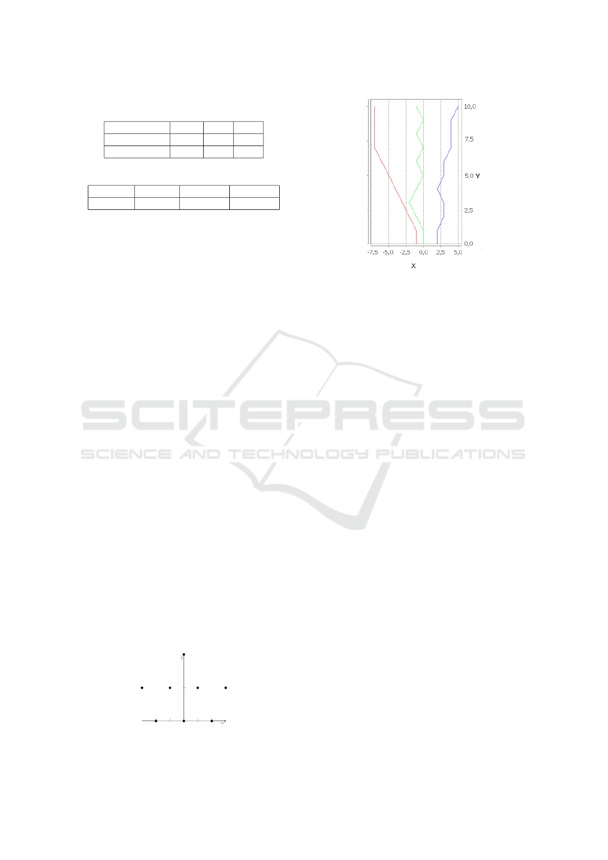
Table 1: Results for 3-UAVs simulations (C: Cooperative,
S: Satisficing, O: Optimal).
C S O
Mean -1.54 1.44 2.95
Std deviation 3.17 4.62 2.58
Table 2: Simulation time for 3, 10 and 20 UAVs.
3-UAVs 10-UAVs 20-UAVs
Time (s) 4.44 9.91 18.08
simulations for each approach (cooperative and sat-
isficing) compared to the optimal. The optimal has
been calculated by searching the maximal score that
the 3 UAVs can reach for each simulation. The fol-
lowing parameters have been set for 3-UAVs simula-
tions: FieldO fView = 3, UAV
1
.X = −1, UAV
2
.X = 0
and UAV
3
.X = 2. Figure 1 shows initial position of
UAVs for 8-UAVs simulation. To show the scalability
of our approach, we present in table 2 the time dura-
tion of 3, 10 and 20 UAVs simulations.
Obtained results show that even if cooperative ap-
proach is competitive, satisficing algorithm seems to
be slightly closest to the optimal for 3 UAVs (Table 1).
This difference seems to come from that our approach
is less effective to prevent long-term difficulties. Nev-
ertheless, additional simulations with 3, 10 and 20
UAVs show the main advantages of our approach (Ta-
ble 2). Indeed, cooperation is a local heuristic ap-
proach more simple to implement than satisficing for
the four following reasons: (i) to construct praxeic
network, designers need to know all the interdepen-
dencies between all component systems before sim-
ulating this kind of application and it may be very
difficult to represent them; (ii) Computation of sat-
isficing global function is resolved with pearl belief
propagation that does not allowed cycles in praxeic
graph (Stirling and Frost, 2005) (i.e. retro action
loop); (iii) the cooperative approach is generic and
does not need global function to calculate satisfic-
ing solutions, so does not need to define a praxeic
network; (iv) the cooperation does not require global
knowledge on the problem, so the failure of a compo-
nent system does not imply recalculation of the solu-
tion. Figure 1 shows that the construction of praxeic
network for 8 (and also for 10, 15 and 20) is com-
plex because UAV interdependencies is hard to no-
Figure 1: Initial positions of 8-UAVs simulation.
Figure 2: Examples of optimal cooperative UAVs trajecto-
ries.
tice. Furthermore if praxeic network is successfully
constructed, this one will have cycles. For example,
UAV in (-1,1) has influences on (0,0) that has influ-
ences on (1,1) that has influences on (-1,1). These
cycles forbid to use pearl belief propagation in order
to solve the Bayesian network associated with praxeic
network. Moreover, times duration of 8, 10, 15 and 20
UAVs simulations (table 2) show that our methodol-
ogy is scalable. Indeed, time duration seems to evolve
in O(log(n)) with n the number of UAVs. Finally, in
satisficing approach, adding a new UAV will lead to
reconstruct the praxeic network so the global func-
tion. At the opposite, our approach enables to eas-
ily add or remove component systems during running
time because there is no need of praxeic graph update.
6 CONCLUSION
This paper proposes a new model to design SoS as
well as a new approach for SoS architecting based
on component system cooperation. We instantiated,
evaluated our approach to a UAV flight scenario and
compared it to satisficing games used in another col-
laborative approach for SoS architecting. Results of
the simulations show that our approach has compet-
itive results comparing to the satisficing one. More-
over, our approach goes through several limitations
such as the definition and the computation of a global
function during the design phase. Finally, last sim-
ulations with more UAVs show that our approach is
easily scalable and enables interdependencies cycles
that are really strong advantages for SoS architecting
evolution. Nevertheless, it seems that our cooperative
algorithm may be improved concerning prediction of
long-term difficulty through criticality. That is why
ICAART 2017 - 9th International Conference on Agents and Artificial Intelligence
180

future work will investigate on this improvement.
REFERENCES
Acheson, P., Pape, L., Dagli, C., Kilicay-Ergin, N.,
Columbi, J., and Haris, K. (2012). Understanding
system of systems development using an agent- based
wave model. Procedia Computer Science, 12:21 – 30.
Complex Adaptive Systems 2012.
Agarwal, S., Pape, L., Kilicay-Ergin, N., and Dagli, C.
(2014). Multi-agent Based Architecture for Acknowl-
edged System of Systems. Procedia Computer Sci-
ence, 28:1–10.
Baldwin, W. and Sauser, B. (2009). Modeling the character-
istics of system of systems. 2009 IEEE International
Conference on System of Systems Engineering (SoSE).
Bonabeau, E. (2002). Agent-based modeling: methods and
techniques for simulating human systems. Proceed-
ings of the National Academy of Sciences, 99(suppl.
3):7280–7287.
Caffall, D. and Michael, J. (2009). System of Systems Col-
laborative Formation. Systems Journal, 3(3):385–401.
Capera, D., George, J., Gleizes, M., and Glize, P. (2003).
The AMAS theory for complex problem solving based
on self-organizing cooperative agents. Proceedings of
the Workshop on Enabling Technologies: Infrastruc-
ture for Collaborative Enterprises, WETICE, 2003-
January:383–388.
Firesmith, D. (2010). Profiling systems using the defining
characteristics of systems of systems (sos). Technical
Report CMU/SEI-2010-TN-001, Software Engineer-
ing Institute, Carnegie Mellon University, Pittsburgh,
PA.
Henshaw, M., Siemieniuch, C., Sinclair, M., Barot, V., Hen-
son, S., Ncube, C., Lim, S., Dogan, H., Jamshidi, M.,
and Delaurentis, D. (2013). The Systems of Systems
Engineering Strategic Research Agenda Systems of
Systems Engineering. (2).
Jamshidi, M. (2008). System of systems engineering - new
challenges for the 21st century. IEEE Aerospace and
Electronic Systems Magazine, 23(5):4–19.
Maier, M. (1998). Architecting principles for systems-of-
systems. Systems Engineering, 1(4):267–284.
Stirling, W. and Frost, R. (2005). Social utility functions-
part ii: applications. IEEE Transactions on Systems,
Man, and Cybernetics, Part C (Applications and Re-
views), 35(4):533–543.
Cooperative Multi-agent Approach for Computational Systems of Systems Architecting
181
