
in-vitro Assessment of Expanded-Polytetrafluoroethylene Stentless
Tri-leaflet Valve Prosthesis for Aortic Valve Replacement
Guangyu Zhu
1, 2
, Masakazu Nakao
3
, Qi Yuan
1
and Joon Hock Yeo
2
1
School of Energy and Power Engineering, Xi’an Jiaotong University,
No. 28 Xian Ning West Rd., 710049, Xi’an, Shaanxi, China
2
School of Mechanical and Aerospace Engineering, Nanyang Technological University,
50 Nanyang Ave., 639798, Singapore, Singapore
3
Department of Cardiothoracic Surgery, KK Women’s and Children’s Hospital,
100 Bukit Timah Rd., 229899, Singapore, Singapore
Keywords: ePTFE, Artificial Heart Valve, Aortic Valve Replacement.
Abstract: Truly stentless polymeric valve prosthesis can be a viable alternative for aortic valve replacement (AVR). In
the present paper, the dynamic and hemodynamic performance of a novel designed expanded-
polytetrafluoroethylene (ePTFE) stentless tri-leaflet valve was assessed experimentally. The in-vitro tests
were performed under time-varying physiological pressure by using the Vivitro pulse duplicator. A high-
speed camera, a flow meter, and pressure transducers were utilized to evaluate the dynamic leaflet behaviours
and coaptation parameters. The maximum effective orifice area, mean pressure gradient, regurgitant volume,
leakage volume and energy loss of the stentless ePTFE tri-leaflet valve are 2.86 cm
2
, 9.89 mmHg, 7.09
ml/beat, 2.81 ml/beat and 129.03 mJ, respectively. The results of the current study may provide a viable option
for the future clinical application.
1 INTRODUCTION
The Ross procedure is a widely accepted surgical
option for the treating of the aortic valve failure (Ross
1967; Talwar et al. 2012; Brancaccio et al. 2014;
Oury et al. 1998). However, for the patients with a
diseased pulmonary valve or in a severe situation, the
standard AVR thus became an alternative treatment
method of the aortic valve failure.
The need for AVR is increasing for pediatric
patients. And the quest for a perfect aortic valve
substitute has been going on for more than fifty years
(Lower et al. 1960). The selection of the ideal
prosthesis for AVR is controversial (Mazzitelli et al.
1998). Multiple surgical options for AVR are
available for these patients, including stented and
stentless porcine valves, porcine valve conduits,
bovine jugular vein conduits, mechanical valves and
mechanical valve conduits. The prosthetic selection
for AVR, however, is still debatable, and all choices
have significant limitations.
The use of polymeric materials for valve leaflets
has been more than 60 years (Roe & Moore 1958).
Polymeric valves’ long-term durability and no need
of permanent anticoagulation combined the
advantages of mechanical valves and bioprosthetic
valves (Sachweh & Daebritz 2006). Among the
polymeric materials, ePTFE valves have shown good
performance in the recent clinical trials in pulmonary
sites(Miyazaki et al. 2011; Miyazaki et al. 2007).
However, there is a lack of information about the
application of ePTFE valves in aortic site. To expand
the current understanding of the performance of the
ePTFE valves in the aortic site, the dynamic and
hemodynamic performance of an ePTFE tri-leaflet
aortic valve prosthesis was assessed in this paper.
2 METHODS
2.1 Preparation of Physical Model
The design parameters of the tri-leaflet valve were
listed in Table 1.
186
Zhu G., Nakao M., Yuan Q. and Yeo J.
in-vitro Assessment of Expanded-Polytetrafluoroethylene Stentless Tri-leaflet Valve Prosthesis for Aortic Valve Replacement.
DOI: 10.5220/0006184401860189
In Proceedings of the 10th International Joint Conference on Biomedical Engineering Systems and Technologies (BIOSTEC 2017), pages 186-189
ISBN: 978-989-758-216-5
Copyright
c
2017 by SCITEPRESS – Science and Technology Publications, Lda. All rights reserved
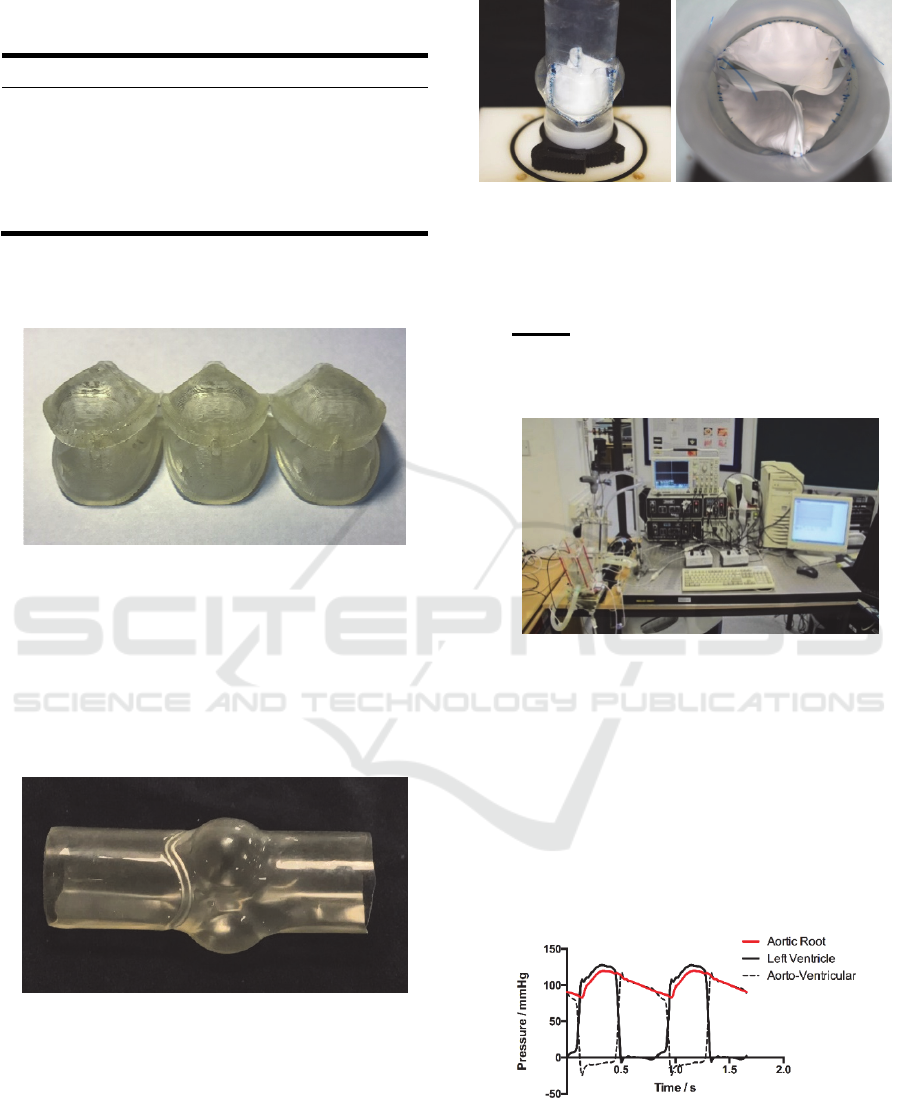
Table 1: Design parameters of the conventional tri-leaflet
valve.
Design Parameters Value
d
b
(mm) 25
d
c
(mm) 25
H
s
(mm) 4
H (mm) 21.9
A (mm
2
) 561.3
A set of resin mold based on the geometry was
fabricated by using 3D printing technology (Figure
1).
Figure 1: 3D Printed Resin Mold.
The valve leaflets were prepared by placing the
ePTFE membrane in-between the mold and cutting
along the edge. The aortic root was constructed by
using the silicon polymer (VTV, MCP-HEK Tooling
GmbH, Kaarst, Germany). Guiding lines were cast
inside the silicon conduits to guarantee the leaflets
can be properly sutured (Figure 2).
Figure 2: Silicon Conduit.
The commissures of the leaflets were sutured to
the aortic root with one running 4-0 polypropylene
suture following the guide line in the conduit (Figure
3).
Figure 3: Valved Conduit.
2.2 Experimental Set-up and Flow
Conditions
The Vivitro pulse duplicator (Vivitro Systems Inc.,
Victoria, BC, Canada) was used to generate the
physiological pressure and flow in the left ventricle
and aorta.
Figure 4: Experimental Setup.
The physiological pressure applied in the in-vitro
investigation was shown in Figure 5. The ventricular
and aortic pressures were measured at the exit of the
left ventricle and the exit of the aorta model by
pressure transducers (SPC 330A, Millar Instruments,
Inc., Houston, TX, USA), respectively. The pressures
were controlled by adjusting the resistor and piston
movement magnitude. The systolic and diastolic
pressure in the aorta is 120 mmHg and 80 mmHg,
respectively.
Figure 5: Time-varying pressure loadings measured in in-
vitro experiment.
All tests were conducted at a stroke volume of 75
ml (5.4L/min) and a heart rate of 72 beats/min. An
aqueous solution of glycerol (42% by weight) was
in-vitro Assessment of Expanded-Polytetrafluoroethylene Stentless Tri-leaflet Valve Prosthesis for Aortic Valve Replacement
187
used as the working fluid to mimics blood. The
dynamic viscosity and density of the working fluid is
3.52 mPa·s and 1038 kg/m
3
, respectively.
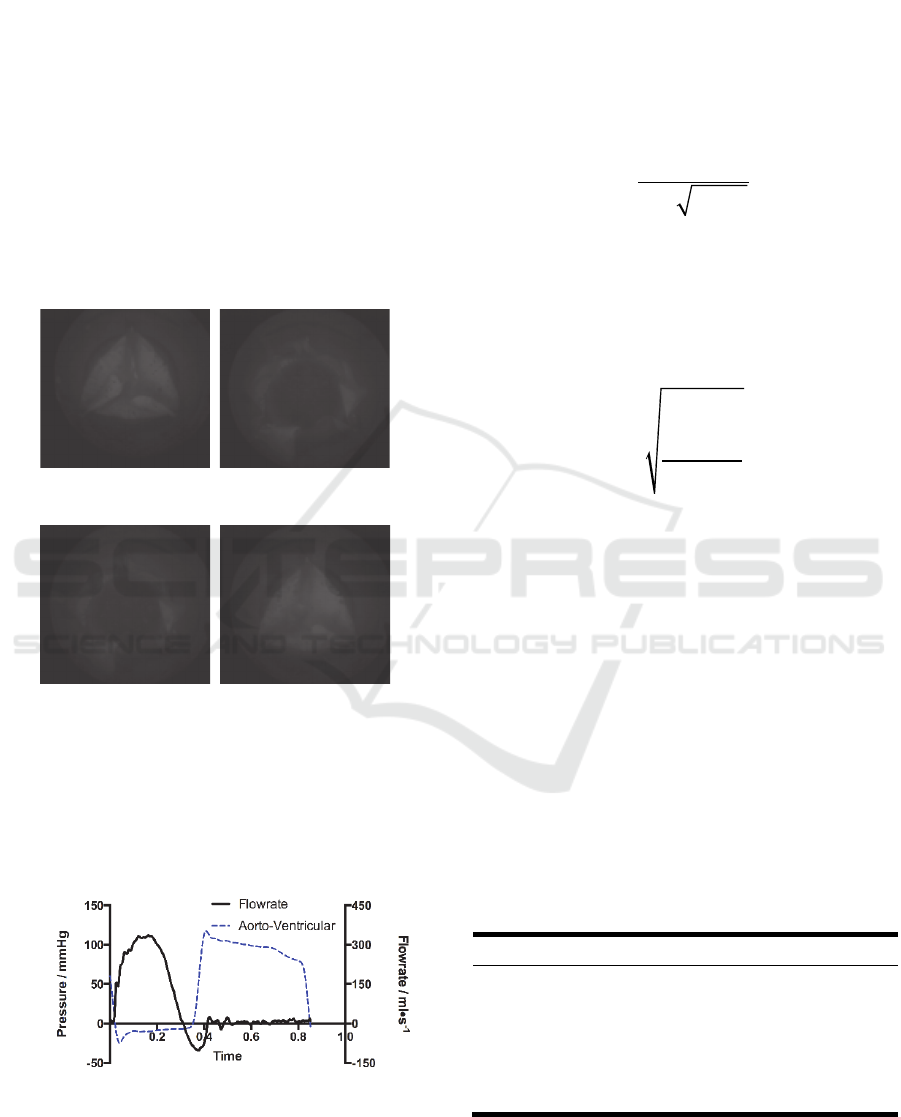
3 RESULTS
To analyze the structural dynamics, key frames from
the film that recorded by the high-speed camera were
extracted (Figure 6). The start point of the record was
defined as t = 0. The opening of the leaflets begins at
t = 0.024s. The opening stage, fully open stage,
closing stage of the valve are 0.12s, 0.132s, and
0.136s, respectively. The leaflets of the valve closed
fully at 0.38s.
t=0.024s t=0.124s
(a) Pre-open (b) Fully opened
t=0.244s t=0.380s
(c) Pre-close (d) Fully closed
Figure 6: Dynamic deformation of the valve leaflets.
The mean trans-valvular pressure of the proposed
valve during the systolic phase is 9.89 mmHg. The
trans-valvular pressure and the aortic flow of the
valves are shown in Figure 7.
Figure 7: Aortic flow rates over one cardiac cycle.
The regurgitant volume (V
R
) and leakage volume
(V
L
) was 7.09 ml and 2.81 ml per cycle, respectively.
Thus the regurgitant fraction (RF) can be calculated
by using the Equation 1:
RF = (V
R
+V
L
)/V
F
×100% (1)
Where V
R
is the regurgitant volume, V
L
is the
leakage volume and V
F
is the forward volume.
The equation from ISO: 5840:2005 (ISO:
5840:2005) was applied to evaluate the maximum
EOA (Equation 2):
A
EO
Q
RM S
51.6 P /
(2)
Where
A
EO
is the orifice area of the valve (cm
2
),
P
is the mean systolic transvalvular pressure
gradient (TPG) in mmHg,
is the working fluid
density (g/cm
3
), and
Q
RM S
is the root mean square
volumetric flow rate (ml/s) (Equation 3).
Q
RMS
Q
2
(t )dt
t
1
t
2
t
2
t
1
(3)
Derived from Bernoulli equation, the energy loss
of the left ventricular that associated with the valve
prosthesis was calculated by integrating the aorto-
ventricular pressure times flow rate with respect to
the time (Bernacca et al. 2002; Claiborne et al. 2013;
Burriesci et al. 2010) (Equation 4):
1
0
0.1333 ( ) ( )
t
L
t
EptQtdt
(4)
Where
E
L
is the energy loss (mJ), to be the
range of a cardiac cycle,
p
is the aorto-ventricular
pressure difference (mmHg) and
Q
(t)
(ml/s) is the
volume flow. The calculated parameters are listed in
Table 2.
Table 2: In-vitro results of the hemodynamic parameters.
Parameters Values
RF (%) 14.37
TPG (mmHg) 9.89
E
L
(mJ) 129.03
Q
RMS
(ml/s) 456.0
EVOA (cm
2
) 2.86
t
0
t
1
BIODEVICES 2017 - 10th International Conference on Biomedical Electronics and Devices
188

4 DISCUSSION AND
CONCLUSIONS
The current study was aimed to assess the
performance of the ePTFE tri-leaflet valve. The
dynamic and hemodynamic performance of the valve
were in-vitro evaluated under in-vitro conditions.
As the well-accepted industry standard, ISO
5480:2055 provides a full set of criterions for
evaluating a valve design (ISO 5480:2055). The
criterions that related with the current study were
listed in Table 3.
Table 3: Minimum performance requirements for aortic
valve prosthesis.
Valve size
(TAD, mm)
25
A
EO
(cm
2
) ≥1.20
RF (%) ≤15
The EOA and RF of the valve that tested in this
study are all satisfied the criterions of the standard.
This validated that the proposed ePTFE valve design
could be a viable choice for AVR operations.
ACKNOWLEDGEMENTS
This study was supported by Singapore National
Medical Research Council
(NMRC/CIRG/1435/2015) and China Postdoctoral
Science Foundation (2016M600781)
REFERENCES
Bernacca, G.M. et al., 2002. Hydrodynamic function of
polyurethane prosthetic heart valves: influences of
Young’s modulus and leaflet thickness. Biomaterials,
23(1), pp.45–50.
Brancaccio, G. et al., 2014. The Ross procedure in patients
aged less than 18 years: the midterm results. The
Journal of thoracic and cardiovascular surgery, 147(1),
pp.383–388.
Burriesci, G. et al., 2010. Design of a novel polymeric heart
valve. Journal of medical engineering and technology,
34(1), pp.7–22.
Claiborne, T.E. et al., 2013. In vitro evaluation of a novel
hemodynamically optimized trileaflet polymeric
prosthetic heart valve. Journal of biomechanical
engineering, 135(2), p.021021.
ISO 5840:2005 - Cardiovascular implants -- Cardiac valve
prostheses.
Lower, D. et al., 1960. Autotransplantation of the pulmonic
valve into the aorta. The Journal of Thoracic and
Cardiovascular Surgery, 39, pp.680-687.
Mazzitelli, D. et al., 1998. Aortic valve replacement in
children: are we on the right track?. European Journal
of Cardio-Thoracic Suregery, 13(5), pp.565-571.
Miyazaki, T. et al., 2011. Expanded polytetrafluoroethylene
conduits and patches with bulging sinuses and fan-
shaped valves in right ventricular outflow tract
reconstruction: Multicenter study in Japan. The Journal
of thoracic and cardiovascular surgery, 142(5),
pp.1122–1129.
Miyazaki, T. et al., 2007. Expanded polytetrafluoroethylene
valved conduit and patch with bulging sinuses in right
ventricular outflow tract reconstruction. The Journal of
thoracic and cardiovascular surgery, 134(2), pp.327–
332.
Oury, J.H. et al., 1998. The Ross procedure: Current
registry results. Annals of Thoracic Surgery, 66(6),
pp.S162-S165.
Roe, B.B. and Moore, D., 1958. Design and fabrication of
prosthetic valves. Experimental medicine and surgery,
16(2-3), pp.177–182.
Ross, D., 1967. Replacement of aortic and mitral valves
with a pulmonary autograft. The Lancet, 290(7523),
pp.956–958.
Sachweh, J.S. and Daebritz, S.H., 2006. Novel
“biomechanical” polymeric valve prostheses with
special design for aortic and mitral position: a future
option for pediatric patients?. ASAIO journal, 52(5),
pp.575–580.
Talwar, S. et al., 2012. Aortic valve replacement with
biological substitutes in children. Asian cardiovascular
and thoracic annals, 20(5), pp.518–524.
in-vitro Assessment of Expanded-Polytetrafluoroethylene Stentless Tri-leaflet Valve Prosthesis for Aortic Valve Replacement
189
