
Automated T Wave End Detection Methods
Comparison of Four Different Methods for T Wave End Detection
Jonathan Moeyersons
1,4
, Griet Goovaerts
1,4
, Suzy Huijghebaert, Bert Vandenberk
2,3
,
Rik Willems
2,3
and Sabine Van Huffel
1,4
1
KU Leuven, Department of Electrical Engineering (ESAT), STADIUS, Kasteelpark Arenberg 10, 3001 Leuven, Belgium
2
KU Leuven, Department of Cardiovascular Sciences, Herestraat 49, 3000 Leuven, Belgium
3
University Hospitals Leuven, Cardiology, Herestraat 49, 3000 Leuven, Belgium
4
Imec, 3001 Leuven, belgium
Keywords: T Wave End Detection, Electrocardiogram (ECG).
Abstract: T wave end detection is essential for electrocardiogram (ECG) processing and analysis. Several methods have
been proposed and tested, but an objective comparison is lacking. In this paper, four different (semi-)
automated methods are compared with the manually annotated T wave ends of the PhysioNet QT database.
The first method is a semi-automatic method, based on a template matching algorithm. The second method
uses the tangent of the steepest point of the descending limb of the T wave. The third and fourth method
perform a maximum area search of, respectively, a trapezium and the area under the curve. In order to evaluate
the accuracy and repeatability of the proposed algorithms, the mean and standard deviation (sd) of the
detection errors were computed. This was performed for leads I and II separately, after selection of the best
annotated T wave end per beat and after selection of the best lead. We demonstrated that the trapezium method
is the least repeatable of all methods tested (sd=29.7ms), whilst the integral method scores best in terms of
accuracy (mean=2.2ms). These findings were strengthened by the analysis of the generated Bland-Altman
plots, where the smallest bias was observed for the integral method (-1.89ms).
1 INTRODUCTION
The QT interval is an indirect measurement of the
time of the depolarization and repolarization of the
ventricular cells. Prolongation of this interval is
associated with the occurrence of lethal ventricular
arrhythmias in patients with the congenital long QT
syndrome (Schwartz and Wolf 1978)(Goldenberg et
al. 2008), in patients taking QT-prolonging non-
antiarrhythmic medication (De Ponti et al., 2002) and
even in the general population (Goldenberg et al.
2006). Therefore, accurate measurement of the QT
interval is of major importance.
Manual detection of the T wave end requires a
time consuming effort of the clinician. Unfortunately,
the great morphological variation in ECG signals
makes it hard to design an automated and widely
applicable algorithm (Manriquez and Zhang, 2007).
Whereas the QRS onset is easily detected, because of
its sharpness, it can be quite challenging to determine
the end of the T wave, since it gradually merges with
the baseline (Couderc and Zareba, 2005).
Furthermore, the presence of U waves might cause
additional difficulties. Large U waves, fused with the
T wave, should be included in the measurement, in
contrast to small and/or separate U waves which
should not be included (Vohra, 2007). During
exercise, the problems with T wave end detection are
even more distinct, since at fast heart rates, the T
wave might fuse with the following P wave (Chauhan
et al., 2002). These facts make it difficult to
automatically detect the end of the T wave.
Despite all these challenges, several algorithms
have been developed using different methodologies.
Since these different algorithms can differ in QT
interval measurement by 10 to 20ms it is important
that a correct detection method is selected (Panicker,
Karnad, Joshi, et al., 2009). This paper is the first to
compare four different (semi-)automated methods on
the same manually appointed T wave ends of the
PhysioNet QT database.
92
Moeyersons J., Goovaerts G., Huijghebaert S., Vandenberk B., Willems R. and Van Huffel S.
Automated T Wave End Detection Methods - Comparison of Four Different Methods for T Wave End Detection.
DOI: 10.5220/0006171700920098
In Proceedings of the 10th International Joint Conference on Biomedical Engineering Systems and Technologies (BIOSTEC 2017), pages 92-98
ISBN: 978-989-758-212-7
Copyright
c
2017 by SCITEPRESS – Science and Technology Publications, Lda. All rights reserved
The first method is a semi-automatic method,
based on a template matching algorithm in which the
user manually selects, hence the semi, the beginning
and the end of the QT interval on a template beat
(Berger et al., 1997). The second method determines
the end of the T wave using the tangent of the steepest
point of the descending limb of the T wave. The third
and fourth method perform a maximum area search
of, respectively, a trapezium (Vázquez-Seisdedos et
al., 2011) and the area under the curve (Qinghua
Zhang et al., 2006). In the following, we will briefly
summarize the four methods mentioned.
2 METHODS
2.1 Method 1: Semi-automatic (SEMI)
T Wave End Detection
The first step of this algorithm is the storage of all
beats, 0.35s before and 0.75s after each R peak.
Hereof the trimmed mean is calculated, excluding the
upper and lower 10% percent of the data, to create a
template representing the average beat. In order to
calculate the QT interval, the distinct features of the
template have to be detected. The template’s R peak
is known, since we segmented the signal based
hereon. The time location of the R peak is denoted
.
Hereafter, the user manually selects the beginning
and the end of the QT interval. This segment is
denoted (n), where is the sample number. Thus,
(
n
)
=
(
)
=
∶
(1)
where () is the ECG signal and
and
are
the manually selected beginning and end points of the
QT interval. The duration of the interval is samples.
For the purpose of matching all other beats to the
template, only the region of the template from =
+
=
is used, with
equal to 50ms.
Per beat, an error function
() is defined:
(
)
=
∑
[
(
+
)
−(
+)]²
(2)
where is the time-stretching factor and
is the
R peak under investigation. The result is the sum of
squared differences between the template T wave and
the stretched or compressed T wave for beat . A
progressive search in the interval [0.91.1] is
conducted in order to find the value of that
minimizes
(
)
. The best value of is denoted
and
the QT interval of the
th
beat is defined as
=
(3)
with, as stated before, equal to the duration of
the template QT interval. The
th
T wave end is
defined by the sum of the
th
QT interval and the
location of the according R peak, minus the length of
the template’s QR interval. In summary, the
algorithm finds the QT interval for each beat such that
the T wave shape best matches the template T wave
under the time-stretch model.
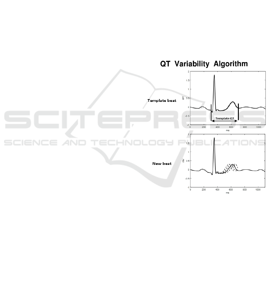
The working principle of this method is
demonstrated graphically in Figure 1. The top panel
presents the template beat. Here, the manually
selected beginning and end of the QT interval are
indicated. The region highlighted in bold is the
segment used to compute the error function. In the
next panel, several time-compressed versions of a
new beat’s T wave are superimposed on the template.
The area of difference between the template T wave
and the uncompressed T wave of the beat is then
calculated and the optimal value of is determined.
Figure 1: Operator selects beginning and end points of the
QT interval from the template (top panel). For each of the
other beats in the epoch, multiple time-compressed or time-
stretched versions of the QT interval are generated (second
panel). These will be used for comparison with the template
QT interval to derive the optimal time-stretching factor .
2.2 Method 2: Tangent Method (TAN)
The first step of this algorithm is again the
segmentation of all beats, 0.35s before and 0.75s after
each R peak. Every beat will be processed and
analysed separately. The second step is an additional
cleaning of each beat using a cubic Savitzky-Golay
filter in order to remove high frequency noise.
Afterwards, the isoelectric baseline of the beat is
Automated T Wave End Detection Methods - Comparison of Four Different Methods for T Wave End Detection
93
aligned with the zero line by subtracting the median
of the first 320ms of the studied beat.
In the third step, a search window is defined in
which the T wave peak is selected. The left bound is
set at 60ms after the R peak, in order to exclude the
QRS complex, but to include the whole T wave. The
right bound is set in the interval between the
suspected end of the T wave and the next R peak. In
this search window the derivative is calculated,
followed by a detection of all sign changes. This
operation results in the location of all peaks and
valleys in the selection window. Subsequently, the T
peak is defined as the peak or valley with the maximal
absolute amplitude in the selection window, but
located maximally 850ms from the start of the beat.
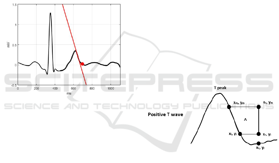
Figure 2: Tangent Method. The red line represents the
tangent of the steepest point of the descending limb of the
T wave and the red dot represents the T wave end.
The fourth step is the selection of the T wave end.
First the steepest point of the descending or ascending
limb of the T wave is defined. Secondly, the tangent
through this point is calculated and the cross point
between this line and the zero baseline is searched.
Finally, since this cross point does not exactly align
with the T end, the point 20ms after the cross point is
selected to be the T end. The working principle of this
method is demonstrated graphically in Figure 2.
2.3 Method 3: Trapezium’s Area
(TRA) Method
The TRA method assumes that T peaks are previously
detected, following the described steps. First, a search
window is defined, which encloses the whole T wave.
Second, the search window is narrowed. The left and
right bound are replaced by the samples with the
maximal and minimal slope in the search window.
Finally, the first point with an absolute slope smaller
than 0.1 is selected and a maximum search of the
absolute values around this point is conducted. The
maximal is referred to as the T peak.
This T wave end detection method is based on the
calculation of consecutive areas of a rectangular
trapezium defined by three fixed and one variable
vertex.
The first fixed point is located 100ms past the T
peak in order to ensure the inclusion of the T wave
end (
,
). The second fixed point is defined by
subtracting each value of a search window in between
the T peak and the first fixed point. A maximum
search is performed and the steepest point of the
descending limb of the T wave is selected (
,
).
The third fixed point is the cross point between a
vertical line through the first and a horizontal line
through the second fixed point (
,
). The variable
point starts at the second fixed point and follows the
graph, until it reaches the first fixed point (
,
).
This is demonstrated graphically in Figure 3. The T
wave end is defined as the point where the area of
the trapezium is maximal. is calculated by the
following formula:
=0.5∗(
−
)∗(2
−
−
)
(4)
This means that the area will be zero when the
variable point equals the second fixed point and
maximum when it is located at the end of the T wave.
Figure 3: Determination of the T wave end by the
computation of the area A of several trapezes. T end denotes
the maximum area.
2.4 Method 4: Integration (INT)
Operation
Based on the R peak detection for each beat, an
interval, [
], is delimited so that the T wave end
is inside this interval, with no overlap with the other
wave forms. The proposed algorithm mainly consists
of the computation of an indicator
which reaches
its maximal value when the T end is detected. It is
computed through an integration operation in a
sliding window, with the window size smaller than
the length of the whole T wave.
is computed by
the following formula:
BIOSIGNALS 2017 - 10th International Conference on Bio-inspired Systems and Signal Processing
94

=
∑
−
̅
(5)
where is the sliding window size in discrete
time,
is the signal value at time point and ̅
is the
mean value of the signal in a small window around .
For each instance inside the earlier defined interval,
the value of
is computed and the T wave end is
located at the value of maximizing
.
3 EVALUATION WITH
MANUALLY ANNOTATED ECG
SIGNALS
The performance of the presented algorithms is
evaluated on the PhysioNet QT database. We
compared the performance of the different detection
methods with the manually annotated T wave ends in
this database.
3.1 The PhysioNet QT Database
The PhysioNet QT database has been designed to
serve as a reference for the validation and comparison
of T wave end detecting algorithms (Laguna et al.
1997). It contains 105 records of 15min two-lead
ECG signals and a total of 3944 T wave end
annotations. The annotations were performed
manually by two expert cardiologists. 3542 T wave
ends were annotated by the first cardiologist and 402
were annotated by the second cardiologist, in 11
recordings. At least 30 beats per record were
annotated, except for 2 records in which no T wave
ends were annotated. The signals are sampled at
250Hz.
Since each detection method uses different types
of filtering, their performance could depend on the
characteristics of the filters. To homogenize this
dependence, the pre-processing was generalized. All
signals were filtered with a zero-phase bandpass filter
between 1 and 40Hz, to correct for baseline drift and
high frequency noise.
3.2 Performance Comparison
In order to evaluate the accuracy and repeatability of
the proposed algorithms, the mean and standard
deviation (sd) of the detection errors, that is the time
difference in ms, between the manually and
automatically detected T wave ends, were computed
for the four different methods in the two ECG leads.
The mean and standard deviation of the errors
were computed as follows. First, the four algorithms
were applied to each of the two leads of an ECG
record in the QT database. Each T wave end is
annotated once by the cardiologists and located twice
by the four algorithms, once per ECG lead. Second,
the detection error is computed. Each manually
annotated T wave end was compared with the
corresponding four automatically annotated T wave
ends. For each lead, the mean detection error and
standard deviation per algorithm was computed.
Finally, the overall mean and standard deviation for
all ECG records were computed.
In Table 1 the results of the validation of the four
proposed algorithms are presented. In row 1 and 2 the
overall mean and sd of lead I and II are presented. The
mean value expresses how close the algorithms are to
the manually annotated markers (accuracy), and the
sd value provides information about the stability
(repeatability) of the detection criteria. The mean
values have to be interpreted with caution, since over-
and underestimation of the manually annotated T
wave ends cancel each other out. This might result in
a lower overall mean value.
Table 1: Comparison of the overall mean and standard
deviation (sd) of the differences, in ms, between the
automatic and manually annotated T wave ends for all
methods in both leads separately.
SEMI TAN TRA INT
Lead mean sd mean sd mean sd mean sd
I -6.2 15.4 -18.0 17.8 25.7 37.2 10.1 21.4
II -2.1 15.9 -5.4 18.0 19.7 36.1 14.9 29.1
The results of Table 1 show that, in terms of the
overall mean error and standard deviation, the TRA
method is outperformed by the other three algorithms,
when evaluated on the PhysioNet QT database.
Although obtained on the same database, this method
showed worse results, compared to the original paper
(Vázquez-Seisdedos et al., 2011). A first explanation
might be the exclusion of some beats in the original
paper due to poor quality of T wave end detection.
Eliminating cardiac cycles of poor quality generally
improves the results. Therefore, evaluating the
detection errors without removing the bad cardiac
cycles puts the proposed algorithms in the least
favourable evaluation condition, which might explain
the difference. The second explanation is the choice
of lead. In this paper, the algorithm is applied on both
leads separately, whilst in the original paper the a
posteriori best result among two computed positions
was chosen for error evaluation (best beat per record
(BB)). In clinical practice, the human operator could
choose the best lead for each patient individually
(best lead per record (BL)), but it is less reasonable to
Automated T Wave End Detection Methods - Comparison of Four Different Methods for T Wave End Detection
95

switch leads per cardiac cycle (Zhang et al., 2005). In
order to take this difference in lead selection into
account, the BB and BL values were also calculated.
The BB values were computed according to the
method adopted first in (Martínez et al., 2004) and
later in (Zhang et al. 2005; Vázquez-Seisdedos et al.,
2011). This method defines the T wave end per beat
by selecting the lead in which the detection error,
between the automatically and manually annotated T
wave end, is minimal. The BL method selects the
ECG lead which contains the most T wave ends,
appointed by the previously described method. If an
equal amount of T wave ends were appointed in both
leads, the first lead was selected. From the viewpoint
of a human operator, this is a more realistic
procedure. The results of both methods can be found
in Table 2.
Table 2: Comparison of the overall mean and standard
deviation (sd) of the differences, in ms, between the
automatic and manually annotated T wave ends for all
methods with the supplementary BB and BL protocol.
SEMI TAN TRA INT
Lead mean sd mean sd mean sd mean sd
BB -4.9 15.1 -8.0 16.3 11.8 29.7 2.2 20.0
BL -6.2 17.6 -7.6 19.0 14.3 37.5 3.9 22.9
When applying the BB protocol, it was observed
that the overall sd, obtained by each of the methods,
was lower compared to the sd obtained for lead I and
II. This was expected, since the lead in which the
detection error is minimal was selected per beat. This
protocol is most in accordance with the annotation
method of the cardiologists, since they made their
annotation by examining both leads and based their
decision on the best lead (Martínez et al., 2004).
In clinical practice, the best lead can be selected
after the ECG recorder is set up. Hence, the BL results
are clinically the most relevant, concerning everyday
T wave end detection. We demonstrated that the TRA
method is the least repeatable of all methods tested
(sd=37.5ms), whilst the SEMI method is the most
repeatable one (sd=17.6ms). The integral method
scores best in terms of accuracy (mean=3.9ms).
It might be noted that the mean and sd calculation
was simplified. One value was computed per record
and the overall mean and sd were computed as the
average of these values. This method does not take
the number of annotated T wave ends in each record
into account. Therefore, we opted to generate Bland-
Altman plots. These allow a direct comparison
between all manual annotations and the T wave end
selections of the four algorithms. Only the BB values
were taken into account, since this protocol is most in
accordance with the annotation method of the
cardiologists. Based on the Bland-Altman plots of the
respective QT intervals, Q being manually annotated
by the cardiologists, an evaluation of the agreement
of the methods was performed. The results of the
evaluation are depicted in Figure 4.
The comparison of the TRA method shows the
largest limits of agreement (-109.10/87.27ms). These
results strengthen the previous findings. In
accordance, the best agreement was determined for
the SEMI method (-75.69/85.01ms), although the
agreement of the INT method was only slightly worse
(-84.48/80.70ms). The obtained biases are in the
range of the ones earlier reported (Panicker, Karnad,
Natekar, et al. 2009; Vázquez-Seisdedos et al., 2011).
The results of the SEMI method could be
explained by the small influence of baseline wander
and U waves on the detection of the T wave end.
Because of their low amplitude, U waves have
significantly less influence on the sum of the squared
differences compared to the T waves. However, it
should be noted that the method is very operator
dependent. This is highlighted by the cluster forming
of the difference points in the Bland-Altman plot. All
QT intervals computed per record will be biased in
accordance to the difference in end point selection of
the template T wave end, compared to the manually
annotated T wave end. This results in a relatively
unaffected QT variability, but alters the QT lengths.
This operator dependency should be taken into
account when using this method in QT interval
analysis.
Besides the agreement intervals, the biggest
difference between the algorithms could be observed
for the cloud on the right. This cloud contains the
longest QT intervals, including biphasic T waves and
fusions with the U wave. Both the TAN and TRA
method were outperformed by the INT method for the
detection of the actual ends of these QT intervals.
Probably, this is due to the fact that the TAN and TRA
method rely on the detection of the T wave peak,
making it harder to detect more complex biphasic T
waves or fused T and U waves.
BIOSIGNALS 2017 - 10th International Conference on Bio-inspired Systems and Signal Processing
96
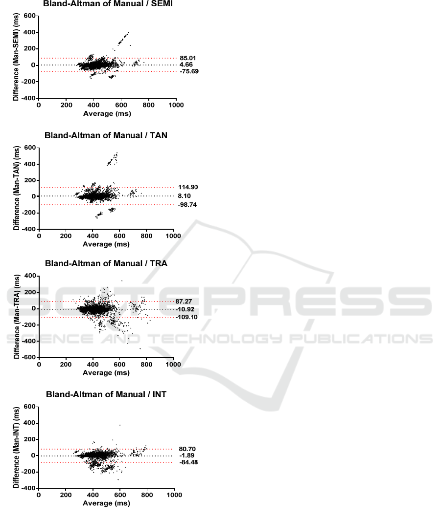
Figure 4: Bland-Altman plots of the four T wave end
detection algorithms, compared to the manual annotated
beats. The dotted black line indicates the average bias, or
the average of the differences. The dotted red lines
represent the 95% limits of agreement.
3.3 Limitations
We annotated the T wave ends on the template beats
for the SEMI method ourselves. Better results could
have been obtained by annotation of the template by
a cardiologist. Also, the tangent and trapezium
method heavily rely on an accurate T peak detection.
This could not be fully guaranteed and might be an
additional cause for the large limits of agreement of
the TRA method. Finally, although the PhysioNet QT
database provides a large database of annotated beats,
it should be noted that it is not known which lead was
annotated. In this paper the BB approach is further
investigated, but it should be noted that this approach
cannot be applied in a clinical setting.
4 CONCLUSIONS
This paper is the first to compare four different
(semi-)automated methods on the same manually
appointed T wave ends of the PhysioNet QT database.
We demonstrated that, in terms of overall mean error
and standard deviation, the TRA method is
outperformed by the other algorithms. The SEMI and
INT methods perform approximately equivalent, but
the SEMI method is very operator dependent.
Therefore, the INT method is the preferred method.
As presented, an important difference remains
between automatically and manually annotated T
wave ends. This is probably due to the previously
mentioned morphological variation, U wave fusion
and omnipresent noise, which also impede manual
annotation.
ACKNOWLEDGEMENTS
RW is supported as a clinical researcher by the Fund
for Scientific Research Flanders (FWO).
SV: BOF KU Leuven: CoE #: PFV/10/002 (OPTEC),
SPARKLE #: IDO-10-0358, The effect of perinatal
stress on the later outcome in preterm babies #:
C24/15/036; FWO: project #: G.0869.12N (Tumor
imaging), G.0A5513N (Deep brain stimulation);
IWT: project #: TBM 110697-NeoGuard, SWT
150466-OSA+; iMinds Medical Information
Technologies: SBO2016; Belgian Federal Science
Policy Office: IUAP P7/19/ (DYSCO, ‘Dynamical
systems, control and optimization’, 2012-2017);
Belgian Foreign Affairs-Development Cooperation:
VLIR UOS programs (2013-2019); EU: European
Union's Seventh Framework Programme (FP7/2007-
Automated T Wave End Detection Methods - Comparison of Four Different Methods for T Wave End Detection
97

2013): EU MC ITN TRANSACT 2012, #316679,
ERASMUS EQR: Community service engineer ,
#539642-LLP-1-2013; The research leading to these
results has received funding from the European
Research Council under the European Union's
Seventh Framework Programme (FP7/2007-2013) /
ERC Advanced Grant: BIOTENSORS (n° 339804).
This paper reflects only the authors' views and the
Union is not liable for any use that may be made of
the contained information. (Tumor imaging)
G.0A5513N (Deep brain stimulation);
REFERENCES
Berger, R.D. et al., 1997. Beat-to-Beat QT Interval
Variability. Circulation, 96(5).
Chauhan, V.S. et al., 2002. Sex differences in QTc interval
and QT dispersion: Dynamics during exercise and
recovery in healthy subjects. American Heart Journal,
144(5), pp.858–864.
Couderc, J.-P. & Zareba, W., 2005. Assessment of
Ventricular Repolarization From Body-Surface ECGs
in Humans. In Cardiac Safety of Noncardiac Drugs.
Totowa, NJ: Humana Press, pp. 107–129.
Goldenberg, I., Moss, A.J. & Zareba, W., 2006. QT
interval: How to measure it and what is “normal.”
Journal of Cardiovascular Electrophysiology, 17(3),
pp.333–336.
Goldenberg, I., Zareba, W. & Moss, A.J., 2008. Long QT
Syndrome. Current Problems in Cardiology, 33(11),
pp.629–694.
Laguna, P. et al., 1997. A database for evaluation of
algorithms for measurement of QT and\nother
waveform intervals in the ECG. Computers in
Cardiology 1997, 24, pp.673–676.
Manriquez, A.I. & Zhang, Q., 2007. An algorithm for QRS
onset and offset detection in single lead
electrocardiogram records. Annual International
Conference of the IEEE Engineering in Medicine and
Biology - Proceedings, (2), pp.541–544.
Martínez, J.P. et al., 2004. A wavelet-based ECG
delineator: evaluation on standard databases. IEEE
transactions on bio-medical engineering, 51(4),
pp.570–81.
Panicker, G.K., Karnad, D.R., Natekar, M., et al., 2009.
Intra- and interreader variability in QT interval
measurement by tangent and threshold methods in a
central electrocardiogram laboratory. Journal of
Electrocardiology, 42(4), pp.348–352.
Panicker, G.K., Karnad, D.R., Joshi, R., et al., 2009. Z-
score for benchmarking reader competence in a central
ECG laboratory. Annals of Noninvasive
Electrocardiology, 14(1), pp.19–25.
De Ponti, F. et al., 2002. Safety of non-antiarrhythmic drugs
that prolong the QT interval or induce torsade de
pointes: an overview. Drug safety, 25(4), pp.263–86.
Qinghua Zhang et al., 2006. An Algorithm for Robust and
Efficient Location of T-Wave Ends in
Electrocardiograms. IEEE Transactions on Biomedical
Engineering, 53(12), pp.2544–2552.
Schwartz, P.J. & Wolf, S., 1978. QT interval prolongation
as predictor of sudden death in patients with myocardial
infarction. Circulation, 57(6), pp.1074–1077.
Vázquez-Seisdedos, C.R. et al., 2011. New approach for T-
wave end detection on electrocardiogram: performance in
noisy conditions. Biomedical engineering online, 10, p.77.
Vohra, J., 2007. The Long QT Syndrome. Heart Lung and
Circulation, 16(SUPPL. 3).
Zhang, Q. et al., 2005. Robust and efficient location of T
wave ends in Electrocardiogram. Computing in
Cardiology (CinC), 32, pp.711–714.
BIOSIGNALS 2017 - 10th International Conference on Bio-inspired Systems and Signal Processing
98
