Compensation Filters for Visualization of White Leds through the
Ceramic Glass in Induction Cooktops
Enrique Carretero, Rafael Alonso and Cristina Pelayo
Department of Applied Physics, University of Zaragoza, C/Pedro Cerbuna, 12, 50009 Zaragoza, Spain
Keywords: Interference Filters, Thin Films, Color Compensation, Illumination.
Abstract: White LEDs visualization in induction cooktops is hindered by the non-uniformity in wavelength of the
transmission of the ceramic glass used as the cooking surface, as it modifies the chromaticity of the LEDs.
In this work, a compensation filter is developed by thin-film interference filter deposition techniques, which
has a transmission spectrum that allows for the preservation of the light source intrinsic chromaticity. This
permits a perfect visualization of white LEDs across ceramic glasses.
1 INTRODUCTION
Nowadays, induction heating cooktops are one of
the most common home appliances. One main
feature of these cooktops is the fact that they use a
ceramic glass as cooking surface, by means of which
they successfully isolate the electronics of the device
from the user. Such ceramic glass must have some
very specific characteristics, as a very low
coefficient of thermal expansion, so that it can
withstand high thermal gradients without cracking
(Siebers et al., 2013).
Currently there are two types of ceramic glasses,
which mainly differ in their optical properties,
particularly in their visible transmittance. On the one
hand, bulk absorption ceramic glass is the typical
black-coloured glass (with low reflection and high
absorption) integrated in most low-medium range
cooktops (SCHOTT, 2010). On the other hand,
transparent ceramic glass can be used on cooktops,
but it requires the deposition of a coating that
confers a proper aesthetic appearance to the cooking
surface (SCHOTT, 2012). This second option is
more expensive and is at present aimed at top-of-
the-range products.
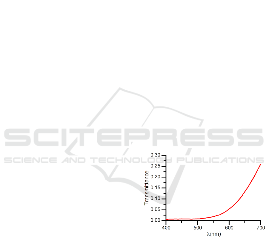
A serious disadvantage of the black-coloured
bulk absorption ceramic glass is the non-uniformity
of its transmittance over the visible spectrum range
(Fig.1). Its transmittance increases with wavelength,
and that is the main reason why signalling and
illumination in induction cooktops has been
traditionally based on red LEDs, as the value of
transmittance at the wavelength of the colour red
(630nm) is higher than for other visible colours
(blue, green…). At present, the strong attenuation
the ceramic glass produces over blue can be
compensated by the enhancement in the
performance of blue LEDs and the use of high
power LEDs.
Figure 1: Visible transmittance of “Brigther
HighTransECO (Schott)” ceramic glass.
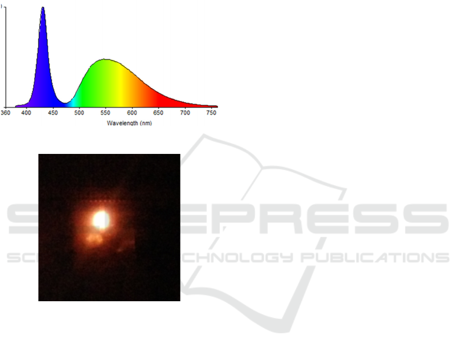
Another significant effect of the use of ceramic
glass on cooktops is the fact that when a light source
with a relatively wide spectrum as a white LED is
used (Fig.2), the non-uniform transmittance of the
glass notably changes the chromaticity of the LED.
This effect implies that a white LED seen through a
bulk absorption ceramic glass is visualised as a pink-
orange colour (Fig.3).
Carretero E., Alonso R. and Pelayo C.
Compensation Filters for Visualization of White Leds through the Ceramic Glass in Induction Cooktops.
DOI: 10.5220/0006167602650268
In Proceedings of the 5th International Conference on Photonics, Optics and Laser Technology (PHOTOPTICS 2017), pages 265-268
ISBN: 978-989-758-223-3
Copyright
c
2017 by SCITEPRESS – Science and Technology Publications, Lda. All rights reserved
265
This work tackles the problem of the
chromaticity change for wide spectrum light sources.
A compensation interference filter has been
designed so that the filter+ceramic glass system has
a closely neutral transmittance in the visible range of
the spectrum. The compensation filter is based on a
multilayer structure of SiAlO
x
and TiO
x
thin films
deposited by magnetron sputtering.
Figure 2: Visible spectrum of a white LED.
Figure 3: Visualization of a white LED through a ceramic
glass.
Interference filter development by means of
dielectric thin films is a well-known technique (J. A.
Dobrowolski, 1995; Macleod, 2010; Thelen, 1989).
In this way, using one dielectric material with a high
refraction index, as TiO
2
with n=2.34 @550nm
(Palik, 1985), and another dielectric material with a
low index of refraction, as SiAlO
x
with n=1.47
@550nm, a transmittance curve can be achieved that
compensates for the non-uniformity of the ceramic
glass transmittance.
TiO
2
is a commonly used dielectric material with
a high index of refraction, so one can easily find
several references in this regard (Willey, 2002). As a
low index material, SiO
2
is more typically used (Gao
et al., 2013; Thelen, 1989), but we have rather
deposited SiAlO
x
films which comprise a low
percentage of Al, because it enhances deposition
conditions (faster sputtering rate, fewer electric arcs
occur during deposition…) and has a very similar
refraction index to that of SiO
2
.
This proposed solution also presents some
advantages for its use with transparent ceramic
glass, because this type of glass requires a multilayer
deposited over its entire surface, while the
compensation filter is only needed in the user
interface area of the cooktop, where the illumination
and signalling elements are placed. Furthermore, the
thermal requirements for the multilayer are less and
can be easily achieved because the filter does not
cover the cooking area.
2 MATERIALS AND METHODS
Optical interference filters were deposited in a semi-
industrial high vacuum magnetron sputtering system
by the DC pulsed technique (Martin, 2009; Mattox,
2010) using rectangular targets with dimensions
600x100mm and 12mm thick. Substrates were
microscope slide pieces of 76x25mm and 1mm
thick. Substrates were cleaned with a detergent
solution (ACEDET 5509) and finally rinsed with
distilled water.
Thin films were grown with a base pressure of
2.0·10
-6
mbar and working pressure in the range of
10
-3
mbar. Ar and O
2
(both 99.99%) flows were
introduced into the process chamber and controlled
via mass flow controllers. The substrate was
maintained at room temperature during deposition.
Thin films of SiAlO
x
were deposited by reactive
sputtering from a SiAl target (90% Si and 10% Al,
99.99% pure). Applied power was 2500W,
equivalent to a power density of 4.17W/cm
2
. The Ar
flow was fixed at 160sccm (Standard Cubic
Centimeters per Minute) and the O
2
flow at 40sccm
(In our deposition system a flow of 200sccm is
approximately equivalent to a pressure of 1.5·10
-3
mbar). Thin films of TiO
2
were deposited by
reactive sputtering from a Ti target (99.99% pure).
Applied power was 5000W, equivalent to a power
density of 8.33W/cm
2
. This power is high because
the sputtering rate of TiO
2
is very low, in this way
we get a reasonable deposition rate. The Ar flow
was fixed at 140sccm and the O
2
flow at 60sccm.
Spectrophotometric measurements were
performed with a home-made spectrophotomer
(designed and built by some of the authors) in the
visible region of the electromagnetic spectrum,
between 400nm and 700nm with 10nm intervals, at
an angle of incidence of 8º. Only specular
transmittance was measured, without an integrating
PHOTOPTICS 2017 - 5th International Conference on Photonics, Optics and Laser Technology
266
sphere, because the “low” roughness of the substrate
minimizes the scattered component to negligible
values and because the specular measurements are
more precise.
The macroscopic roughness of the internal side
of the ceramic glass makes it difficult to measure its
specular transmittance. An epoxy resin (epo-tek 301
type) with a low optical absorption and an index of
refraction similar to that of the ceramic glass was
applied to correct that roughness, and to stick the
compensation filter to the ceramic glass.
3 RESULTS
The transmittance spectrum of the compensation
filter should be one that meets the following
expression in the visible region of the spectrum:
filter glass
TT cte
(1)
If the filter+ceramic glass system has a constant
transmittance, it won’t unbalance the wide spectrum
of the illumination source, so there won’t be certain
wavelengths gaining weight and the compensation
effect won’t be achieved.
Therefore, one can calculate the transmittance
curve of the compensation filter from the measured
transmittance curve of the ceramic glass. Once we
knew the target transmittance, we proceeded to the
design of the multilayer using a simulation software
that is based on formalisms used for the calculation
of optical properties for interference coatings
(Macleod, 2010; Thelen, 1989).
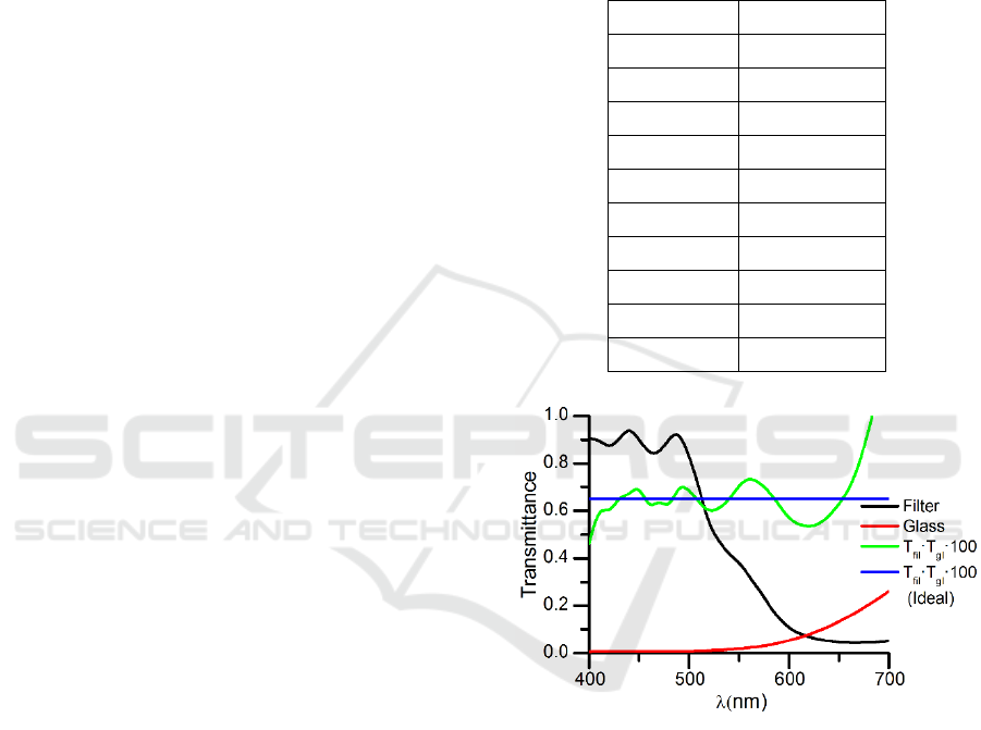
A 9-layer structure was estimated as satisfactory
enough to achieve the necessary contrast between
high and low transmittance areas for an adequate
compensation filter (Table 1).
Figure 4 shows the transmittance curves for an
ideal filter+ceramic glass system (calculation, blue
line) and for the real system (measured, green line).
The transmittance absolute value of the ideal system
has been located at 0.65% because the ceramic glass
transmittance in the wavelength range of the blue
colour is around 0.70%, and this value represents an
upper limit. The transmittance curve of the
experimentally made system is close to the ideal
value, although in the limits of the visible range of
the spectrum we find more discrepancies, but in this
range the human eye sensitivity is low, so this zone
has less relative weight when determining the
chromaticity of the light source that is used. In this
way, a discrepancy lower than 15% is accomplished
between the ideal and real measured values of
transmittance, whereas the ceramic glass without the
filter has a transmittance which is 10 times lower at
460nm (blue peak of a white LED spectrum) tan at
620nm (where the phosphorescent emission of the
LED is still high and human eye sensitivity is still
considerable).
Table 1: Thin film structure and layer thicknesses of the
compensation filter.
Material Thickness (nm)
Substrate 1 mm
TiO
2
85
SiAlO
x
143
TiO
2
72
SiAlO
x
116
TiO
2
70
SiAlO
x
104
TiO
2
69
SiAlO
x
93
TiO
2
78
Figure 4: Transmittance curves for: compensation filter
(black line), ceramic glass (red line), real filter+ceramic
glass system (green line) and ideal filter+ceramic glass
system (blue line).
By using a greater number of layers, we can
better adjust the experimental system to the ideal
one, as a greater number of adjustment parameters
for the multilayer appear (i.e., the thicknesses of
each layer). Nevertheless, it has been proven that the
developed filter achieves good results and manages
to correct the chromaticity change for white LEDs.
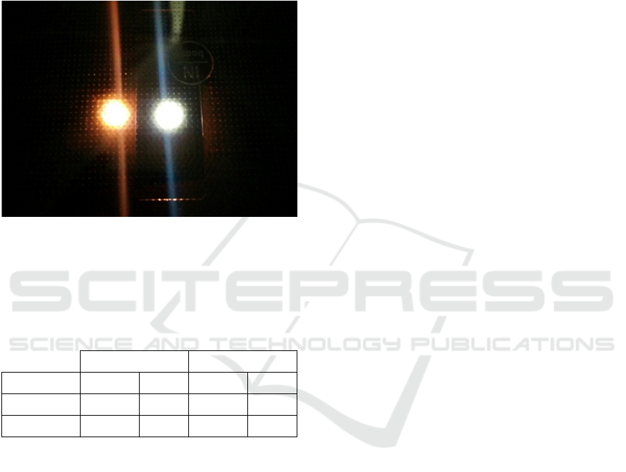
Figure 5 finally shows the visualization of two white
LEDs through a ceramic glass, illustrating the effect
of the compensation filter, which accomplishes the
goal of a good colour reproduction.
Compensation Filters for Visualization of White Leds through the Ceramic Glass in Induction Cooktops
267
The chromaticity coordinates of a light source
having the spectrum of the D65 illuminant seen
through a ceramic glass are far from the white colour
coordinates, as well as those of a typical white LED
seen through a ceramic glass. However, when the
compensation filter+ceramic glass system is used,
the chromaticity coordinates in both cases are within
the zone of the white colour (Table 2).
Figure 5: Visualization of a white LED through a ceramic
glass: without compensation filter (left) and with
compensation filter (right).
Table 2: Chromaticity coordinates for the ceramic glass
and for the compensation filter+ceramic glass system,
expressed by using the D65 illuminant and a white LED
(Osram model LW W5SM).
Ceramic glass Cer. glass+filter
Illuminant D65 LED D65 LED
x 0.54 0.52 0.31 0.32
y 0.37 0.38 0.33 0.32
4 CONCLUSIONS
This work verifies that thin-film interference optical
filters can be used to compensate the non-uniformity
in transmittance of the ceramic glass that is used in
induction cooktops. There are several alternative
manufacturing methods for such filters, but optical
interference filters allow a greater adjustment of its
transmittance curve. In this case, a nine-layer
structure alternating TiO
2
(high index of refraction)
and SiAlO
x
(low index of refraction) layers is
necessary. Adding this filter into the illumination
and signalling area of induction cooktops, we can
correct the chromaticity change that the ceramic
glass introduces for wide spectrum light sources,
such as white LEDs. This effect has been verified
not only visually but also by calculation of the
chromaticity coordinates for light sources with
spectra of the D65 illuminant and of a white LED.
ACKNOWLEDGEMENTS
We thank Carmen Cosculluela for her valuable help.
This work was partly supported by the Spanish
MINECO under grant RTC-2014-1847-6, in part by
the Diputación General de Aragón / Fondo Social
Europeo through the funding for the Photonics
Technologies Group (GTF), in part by the
Diputación General de Aragón under FPI
programme B143/12 and in part by the BSH Home
Appliances Group.
REFERENCES
Gao, L., Lemarchand, F., Lequime, M., 2013. Refractive
index determination of SiO2 layer in the UV/Vis/NIR
range: spectrophotometric reverse engineering on
single and bi-layer designs. J. Eur. Opt. Soc.-Rapid
Publ. 8, 13010. doi:10.2971/jeos.2013.13010.
J. A. Dobrowolski, 1995. Optical properties of films and
coatings, in: Handbook of Optics. McGraw-Hill.
Macleod, H.A., 2010. Thin-Film Optical Filters, Fourth
Edition. CRC Press.
Martin, P.M., 2009. Handbook of Deposition Technologies
for Films and Coatings: Science, Applications and
Technology. William Andrew.
Mattox, D.M., 2010. Handbook of Physical Vapor
Deposition (PVD) Processing. William Andrew.
Palik, E.D., 1985. Handbook of optical constants of solids.
Academic Press, Orlando.
SCHOTT, 2012. CERAN CLEARTRANS Cooktops
Panels, Technical Delivery Specification TL 1 09 23
01 - 02.
SCHOTT, 2010. CERAN HIGHTRANS eco Cooktops
Panels, Technical Delivery Specification TL 1 07 04
01 - 03.
Siebers, F., Weiss, E., Gabel, F., 2013. Glass ceramic as a
cooktop for induction heating having improved
colored display capability and heat shielding, method
for producing such a cooktop, and use of such a
cooktop. US2013201678.
Thelen, A., 1989. Design of Optical Interference Coatings.
McGraw-Hill.
Willey, R.R., 2002. Practical Design and Production of
Optical Thin Films. CRC Press.
PHOTOPTICS 2017 - 5th International Conference on Photonics, Optics and Laser Technology
268
