
Specularity, Shadow, and Occlusion Removal
for Planar Objects in Stereo Case
Irina Nurutdinova, Ronny H
¨
ansch, Vincent M
¨
uhler, Stavroula Bourou, Alexandra I. Papadaki
and Olaf Hellwich
Computer Vision and Remote Sensing, Technische Universit
¨
at Berlin, Marchstr. 23, MAR6-5, 10587 Berlin, Germany
{irina.nurutdinova, r.haensch, olaf.hellwich}@tu-berlin.de
Keywords:
Specularity Removal, Shadow Removal, Occlusions, Planar Objects, Specular-free Image, Shadow-free
Image, Occlusion-free Image.
Abstract:
Specularities, shadows, and occlusions are phenomena that commonly occur in images and cause a loss of
information. This paper addresses the task to detect and remove all these phenomena simultaneously in order
to obtain a corrected image with all information visible and recognizable. The proposed (semi-)automatic
algorithm utilizes two input images that depict a planar object. The images can be acquired without special
equipment (such as flash systems) or restrictions on the spatial camera layout. Experiments were performed
for various combinations of objects, phenomena occurring, and capturing conditions. The algorithm perfectly
detects and removes specularities in all examined cases. Shadows and occlusions are satisfactorily detected
and removed with minimal user intervention in the majority of the performed experiments.
1 INTRODUCTION
When photographing certain objects one is often
faced with problems such as specularities, shadows,
or occlusions. The properties of planar objects such as
posters or books (i.e. being flat and reflective), the sit-
uation during image acquisition (e.g. crowded scenes
during a poster presentation), as well as the fact that
this type of images is usually taken to store informa-
tion, make these problems especially severe in this use
case. Figure 1(a) shows an example of all three phe-
nomena and their effects on the image quality.
These effects commonly cause a loss of important
information such as missing details in text and figures,
are often beyond the control of the photographer, and
can only marginally be resolved by postprocessing.
However, they vary often with the viewpoint of the
camera. While it might not be possible to find or use
a viewpoint which allows to acquire images without
these effects, different object parts will be corrupted
if the images are taken from different positions.
This paper presents a practical solution to these
problems by detecting and removing specularities,
shadows, and occlusions for planar objects. The de-
veloped algorithm processes two input images taken
from different views, captured by a consumer camera
or a mobile phone. The proposed method does not re-
quire any professional equipment, such as high reso-
(a) Source (b) Target (c) Corrected
Figure 1: Specularities, shadows, and occlusions are auto-
matically detected and removed leading to a visually pleas-
ing result.
lution cameras, polarization filters, or flash structures.
It does not rely on a specific spatial relation between
camera and object, e.g. the distance to the object and
the viewpoint of the camera, as long as the images of
the object have a sufficient quality. The final result is
a corrected image (see Figure 1(c) for the input im-
ages in Figures 1(a)-1(b)), that is free of specular ar-
eas, shadows, and occlusions, where the text is read-
able, the figures are complete, and the overall quality
is close to that of a frontal, unoccluded picture.
The proposed method is implemented as a C++
desktop application and Android mobile app. It can
be run automatically, but also allows interactive user
input to improve results. The implementation is open
source and freely available (Nurutdinova et al., 2016).
98
Nurutdinova I., HÃd’nsch R., MÃijhler V., Bourou S., I. Papadaki A. and Hellwich O.
Specularity, Shadow, and Occlusion Removal for Planar Objects in Stereo Case.
DOI: 10.5220/0006166100980106
In Proceedings of the 12th International Joint Conference on Computer Vision, Imaging and Computer Graphics Theory and Applications (VISIGRAPP 2017), pages 98-106
ISBN: 978-989-758-225-7
Copyright
c
2017 by SCITEPRESS – Science and Technology Publications, Lda. All rights reserved

2 RELATED WORK
Although there are many methods aiming at the de-
tection of specularities, shadows, or occlusions, the
majority of those approaches deals with only one of
these phenomena.
An overview of specularity removal techniques
can be found in (Artusi et al., 2011). Methods for
specularity detection can be divided into two groups
based on whether they use a single or multiple images
as input. The technique in (Klinker et al., 1988) an-
alyzes the color space of a single image in order to
estimate the distribution of specular pixels. The work
in (Mallick et al., 2006) is based on a single image as
well, analyzes the spatial neighborhood of a pixel, and
uses partial differential equations to iteratively erode
the specular components. The method of (Yang et al.,
2013) separates specular and diffuse components in
the HSI color space, clusters pixels with similar char-
acteristics, and subsequently finds the optimal satura-
tion.
Multi-image methods use multiple input images
of the same scene but obtained from different points
of view. The work in (Lin et al., 2002) uses color
histogram differencing to retrieve specular pixels. It
is based on color changes of specular regions among
the different views which are estimated by computing
the distance of the corresponding color histograms.
The method for specularity removal of flat objects
proposed in (Biasotti et al., 2015) employs a pixel
value minimization across multi-view images which
are captured by a mobile phone. It requires known
camera orientation for each image, which is obtained
by the built-in inertial measurement unit. The refer-
ence image is selected to be approximately parallel to
the scanned surface.
A second category of approaches includes meth-
ods that require special equipment. The multi-
flash method in (Feris et al., 2004) demands a flash
system and uses an image sequence captured from
fixed viewpoints with different positions of flash-light
sources. The work in (Ma et al., 2007) is based on the
fact that specular components of the reflected light are
polarized. To separate these components, this method
needs suitable polarization filters to measure the re-
flected light.
The detection of shadows is an important pre-
processing step in many computer vision applications.
The corresponding methods can be coarsely divided
into pixel- and region-based approaches. An example
of the former is the method in (Murali and Govindan,
2013) which detects shadows of a single image in the
CIELab color space. The work in (Guo et al., 2011) is
a region-based approach that classifies regions of the
segmented image as shadow or non-shadow, accord-
ing to their relative illumination.
Specularities and shadows can also be handled
by deriving intrinsic images that decompose an im-
age into its reflectance and illumination component.
For example, the method in (Weiss, 2001) applies
two derivative filters to a sequence of images to re-
cover individual illumination images and a single re-
flectance map which is almost free of specularities
and shadows. Several multi-view approaches for out-
door scenes (Laffont et al., 2013; Duch
ˆ
ene et al.,
2015) compute a proxy geometry of the scene and uti-
lize it for illumination estimation.
Occlusions can be considered as one of the biggest
challenges in stereo vision. In (Zitnick and Kanade,
2000) the authors introduce a cooperative stereo algo-
rithm. It is based on an uniqueness assumption and
is jointly creating disparity maps as well as detect-
ing occlusions. In order to detect occlusions in two-
frame stereo, the iterative optimization algorithm in
(Sun et al., 2005) uses a visibility constraint which is
more general than the uniqueness constraint of (Zit-
nick and Kanade, 2000).
The technique proposed in this paper does not re-
quire any special equipment. Furthermore, two input
images from two different viewpoints are sufficient
while there are no specific constraints on the spatial
relation between the two cameras and the object. In
contrast to works such as (Biasotti et al., 2015), it
is not necessary to determine the orientation of the
cameras. Consequently, there is no predefined cri-
terion for the selection of an image as the reference
frame. The main contribution of the proposed ap-
proach is the creation of a corrected image, free of
specularities, shadows, as well as occlusions for a pla-
nar object, even if the images contain all these unde-
sired phenomena. The simplicity of the developed al-
gorithm makes it robust and applicable in many use
cases, i.e. it does not depend on specific image acqui-
sition circumstances, high-end cameras, or other spe-
cial equipment. Instead, images can be captured by
hand-held consumer or mobile phone cameras from
arbitrary viewpoints.
3 PROPOSED ALGORITHM
Specularities, shadows, and occlusions are effects that
most commonly and most strongly affect the visibil-
ity of objects in images. They become especially se-
vere in the case of images of planar and reflective
surfaces which were acquired in crowded scenarios,
e.g. posters in the interactive sessions of a conference.
That is why the proposed technique focuses on the
Specularity, Shadow, and Occlusion Removal for Planar Objects in Stereo Case
99
joint detection and removal of these three phenomena
for planar objects based on at least two images.
The goal of the algorithm is to create a corrected
image, which is rectified and free of these phenom-
ena by replacing corrupted regions with information
from the input images. For this purpose, one image is
selected as target image T that will provide the basis
for the alignment, while affected regions are replaced
by non-corrupted information from the other image,
i.e. the source image S. An obvious requirement of
this approach is that at least one of the input images
needs to contain non-corrupted information for all ob-
ject parts that are corrupted in the target image. In
the case when a certain object area is corrupted in all
input images, no correction can be performed unless
more images of the object are taken.
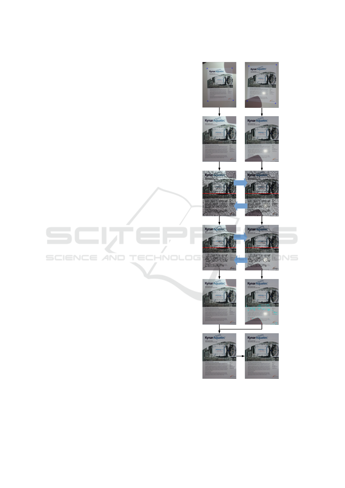
This section presents the individual steps of the
developed algorithm as shown in Figure 2, starting
from a pair of input images until the creation of the
corrected image.
3.1 Object Rectification
For the subsequent detection and correction steps (as
described in Sections 3.3-3.5) it is sufficient to only
align the given input images. However, potentially,
none of the input images was captured with an image
plane parallel to the object plane, leading to skewed
projections of the object in all images. Furthermore,
a significant part of the image might show the back-
ground, which might have a different depth than the
object itself, leading to ambiguities during the auto-
matic alignment (see Section 3.2).
That is why the proposed approach starts with an
optional but recommended rectification step. The ob-
ject is assumed to be rectangular (e.g. a poster or
book) and its four corner points (see first row of Fig-
ure 2) are mapped to a predefined rectangular region
by a first initial homography for source and target im-
age, respectively. This step allows the user to spec-
ify the region of interest and increases the robustness,
accuracy, and speed of the subsequent feature-based
image alignment.
3.2 Image Alignment
The coarse initial alignment (Section 3.1) is not suffi-
ciently accurate, if the corner points within the input
images do not perfectly match each other. That is why
this step computes a finer alignment based on key-
points detected by SIFT (Lowe, 2004) and matched
among the images. If the optional object rectification
step is left out (e.g. if one of the input images shows a
sufficiently rectangular projection of the object with-
Input Images
Rectified Images
Fine Segmentation
Coarse Segmentation
Detection
Copied Information Corrected Image
S / T
T / S
S / T
T / S
Source Target
Figure 2: The pipeline of the developed technique, starting
from two input images until the creation of the corrected
image. The blue circles in the images of the first row denote
the user-selected corners of the region of interest.
VISAPP 2017 - International Conference on Computer Vision Theory and Applications
100

out too much background), this fine alignment is the
first step of the whole processing chain.
RANSAC (Fischler and Bolles, 1981) is utilized
to find the inliers of the obtained point correspon-
dences, which are used for the calculation of the fi-
nal homography which maps the (rectified) source im-
age into the coordinate system of the (rectified) target
image. Using this homography, the source image S
is warped to the coordinate system of the target im-
age T . Regions in the target image, that are not visi-
ble in the warped source image, are masked out in all
subsequent steps. The second row of Figure 2 shows
the result of the object rectification and alignment of
the two input images shown in the first row.
3.3 Image Segmentation
Image segmentation is the next step of the proposed
processing chain for several reasons. First of all, spec-
ularities as well as shadows and occlusion are regional
phenomena that never affect single pixels but always
whole parts of an image. Furthermore, methods based
on isolated pixels are prone to incorrect classification
due to image noise and imprecise image alignment.
For this reason, the proposed method performs a clas-
sification that is based on image segments (e.g. super-
pixels) instead of single pixels by detecting color dif-
ferences between segments of the target and source
image. This does not only lead to an increased ro-
bustness and accuracy, but also to a significantly de-
creased computational load.
The two aligned input images are segmented into
superpixels by SEEDS (van den Bergh et al., 2015),
which is sufficiently fast, prevents over-segmentation
of the image, and automatically determines the num-
ber of segments. In a second step the segment bound-
aries of the target image are projected into the source
image leading to a target-source (T/S) segmentation
and the segment boundaries of the source image are
projected into the target image leading to a source-
target (S/T) segmentation (an example is shown in the
third row of Figure 2. This allows a valid comparison
between image regions of the two images by avoid-
ing the risk that two corresponding regions only have
a mutual overlap but also contain disjoint parts of the
image.
While the T/S segmentation is used to detect spec-
ularities, shadows, and occlusions in the target image,
the S/T segmentation is used to detect shadow and
occluded regions within the source image. It should
be noted, that images without any deterioration would
result in an equivalent S/T- and T/S segmentation (up
to small variations due to noise). Significant differ-
ences in both segmentations are due to additional ”ob-
jects” or features in the images such as specular re-
gions, shadows, and occlusions.
This segmentation procedure leads to four dif-
ferent sets of superpixel
n
s
α,β
i
o
i=1,...,N
α
, namely the
S/T-segmentation derived from the source image
(α = S /T , β = S) and projected to the target image
(α = S /T,β = T ), as well as the T/S-segmentation
derived from the target image (α = T /S,β = T ) and
projected to the source image (α = T /S,β = S). For
the sake of brevity the indices α,β are skipped, when-
ever they are not explicitly needed.
Each superpixel s
i
is described by the mean color
value of its pixels in CIELab space, denoted as
m(s
i
) = (m
L
(s
i
),m
a
(s
i
),m
b
(s
i
)), where m
c
(s
i
) with
c ∈ {L,a,b} is the mean value of the lightness and
color-opponent channels, respectively.
While specularities often only affect rather small
image regions that are sufficiently represented by su-
perpixels, shadows and occlusions commonly cover
large parts of the images. In order to obtain a larger
spatial support and a more stable detection of these
effects, superpixels are merged into larger image re-
gions. The merging process is applied to superpixels
n
s
S/T,S
i
o
and
n
s
T /S,T
i
o
only, whereas the resulting re-
gions
n
r
S/T,S
u
o
and
n
r
T /S,T
v
o
are projected into the
other image to obtain regions
n
r
S/T,T
u
o
and
n
r
T /S,S
v
o
.
The regions are formed by merging neighboring
superpixels with similar colors. The region growing
is initialized by defining each superpixel s
i
as a re-
gion r
u
of this image (where m(r
u
) is the mean color
vector of region r
u
). An iterative process merges two
adjacent regions r
u
,r
v
into one region if the condition
in Equation (1) is fulfilled.
km(r
u
) − m(r
v
)k
2
< m (1)
The default values of the thresholds m = 4 has
been determined empirically and is strict enough to
preserve clear borders of most objects and shadows.
Small regions with area below 5% of the image size
are merged with the most similar adjacent regions, i.e.
the ones with lowest difference of the mean color.
Figure 3(b) depicts the regions created by merging
the superpixels of Figure 3(a).
3.4 Detection
In the detection step the previously obtained segmen-
tation is used to classify image parts into specular re-
gions, shadows, occluded, or not problematic regions.
The classification is based on color differences be-
tween the segments within the aligned images.
Specularity, Shadow, and Occlusion Removal for Planar Objects in Stereo Case
101

(a) Superpixels obtained by
SEEDS
(b) Regions obtained by
merging procedure
Figure 3: Result of image segmentation and merging.
While the shadow/occlusion detection (Sec-
tion 3.4.1) operates on regions, the specularity detec-
tion (Section 3.4.2) uses the original superpixels (see
Section 3.3).
3.4.1 Shadow and Occlusion Detection
Shadows and occluding objects usually appear as dis-
tinct, rather large areas with clear borders. Exploit-
ing this characteristic, shadows and occlusions are de-
tected as connected regions with sharp edges that are
visible in one but not in the other image. For this rea-
son the shadow and occlusion detection is based on
the regions formed during the segmentation process
as described in Section 3.3.
The neighborhood N(r
u
) is the set of all regions
within the same image, that are adjacent to region r
u
,
i.e. share a common border. Let ∂r
u
be the set of
superpixels at the border of region r
u
, i.e. each super-
pixel s
i
∈ ∂r
u
has at least one adjacent superpixel s
j
which belongs to a neighboring region r
v
, i.e. s
j
∈ r
v
with r
v
∈ N(r
u
). The exterior neighborhood N
e
(s
i
) of
a superpixel s
i
∈ ∂r
u
is the set of all adjacent super-
pixels which do not belong to the same region:
N
e
(s
i
) = {s|s ∈ ∂r
v
with v 6= u and r
v
∈ N(r
u
)} (2)
For each superpixel s
i
∈ ∂r
u
, the intensity differ-
ence to the superpixels in the exterior neighborhood
N
e
(s
i
) is computed and used to assign the correspond-
ing label y to this superpixel by Equation (3).
y(s
i
) =
(
1, if ∃s ∈ N
e
(s
i
) : m
L
(s) − m
L
(s
i
) > t
grad
0, otherwise.
(3)
It should be noted that only object borders are
marked where the interior superpixels are darker than
the exterior.
After the object borders are defined according to
Equation (3), they are compared among the different
images. Each superpixel s classified as an object bor-
der in only one of the segmented images casts a vote
to its underlying region r
u
with s
i
∈ r
u
to be an ad-
ditional object. The normalized sum of all votes in
Equation (4) is considered as a cue for a shadow or
occlusion.
Y
α
(r
u
) =
1
|∂r
u
|
∑
s∈∂r
u
(1 − δ(y(s
α,S
),y(s
α,T
))) (4)
where α ∈ {S/T,T /S} and δ(·, ·) is the Kronecker
delta function.
If a region r has sufficient number of votes, it is
classified as shadow or occluded region. Specifically,
if Y (r
u
) > a where 0 ≤ a ≤ 1 is a constant.
A shadow/occluded region which is surrounded
by other shadow/occluded regions might not obtain
a sufficient number of votes, since the color differ-
ence between the corresponding boundary superpix-
els is too small. Thus, regions that share at least 80%
of their border with other shadow/occluded regions
are labeled as shadow/occluded as well.
3.4.2 Detection of Specularities
Specularities appear as regional phenomena usually
smaller in size as occlusion and shadows. With the
exception of strong and distinct highlights, the bor-
ders are often smooth and gradually change to the true
intensity of the object. Typical examples are specular-
ities such as highlights, reflected light flashes, mirror-
like reflections, and overexposed areas.
The detection is based on the assumption, that a
specular segment has a higher intensity value, since
the color of the specular component adds to the under-
lying diffuse color. Therefore if Equation (5) holds,
superpixel s
α,T
i
is categorized as a specular candidate
and is added to the specularity mask of the source im-
age.
m
L
s
T /S,T
j
− m
L
s
T /S,S
j
> t
spec
(5)
The threshold t
spec
is automatically determined
based on the average intensity difference of all cor-
responding superpixels in target and source images.
Since shadows and dark occlusions in the source
image appear brighter in the target image and thus ful-
fill Equation 5 as well, only superpixels are consid-
ered that have not been classified as shadow/occluded
regions before. This effect is shown in Figure 4,
where Figure 4(c) shows the result if this condition
is not considered. Figure 4(d) shows the result if the
previously performed shadow detection is exploited.
VISAPP 2017 - International Conference on Computer Vision Theory and Applications
102

(a) Target image (b) Source image
(c) Result using initial
specularity mask.
(d) Result using final spec-
ularity mask.
Figure 4: Specularity detection.
3.5 Image Correction
After all problematic regions in the source and tar-
get image have been defined and classified, they are
used to obtain the corrected image which is free of
those effects. In a first step, all detected problem-
atic regions in the target image are combined to a re-
placement mask. There might occur small holes or
small regions in this mask which are caused by fusing
the different detections. They are filled or deleted,
respectively, as a tradeoff between completeness of
the replacement and visual consistent results: A very
small shadow, occlusion, or specularity is unlikely to
decrease the overall information content much, but
small errors during the image registration might cause
small misalignments which become most apparent for
diagrams or text regions.
The entire area of the final mask is replaced in the
target image by the corresponding area of the source
image. The result is shown in Figure 5(c).
Due to different exposure and color balance of the
two images, it is very likely that the replaced regions
are clearly recognizable by color differences creating
edges in the image which are not part of the object
itself. Poisson Blending (Per
´
ez et al., 2003) is used to
seamlessly blend them with the regions of the target
(a) Target image (b) Source image
(c) Result without Poisson
Blending.
(d) Result with Poisson
Blending.
Figure 5: Replacement of corrupted regions.
image. The main goal of this step is to obtain a visual
consistent and pleasing corrected image, while fine
details such as text in the blended areas are preserved.
The final corrected image after Poisson Blending is
shown in Figure 5(d).
4 USER INTERACTION
The proposed approach is often able to automatically
detect and remove specularities, shadows, and oc-
cluded areas from the target image, provided that the
corresponding regions are not degraded by these ef-
fects in the source image. However, the results of the
method can be improved by minimal user interaction
at three major points:
1. Object Rectification: As mentioned in Sec-
tion 3.1, an object rectification can be performed
which leads to an corrected image that shows only
Specularity, Shadow, and Occlusion Removal for Planar Objects in Stereo Case
103
the object of interest in a rectangular shape with-
out any background. In this case, the user selects
the four corner points of the object in the images
which are then mapped to a predefined rectangle.
2. Shadow and Occlusion Detection: The distinct
properties of specularities (i.e. small, very bright
areas) make them easier to detect than shadows
and occlusions, which can be very inhomoge-
neous and of (nearly) arbitrary shape.
While the proposed method provides an auto-
matic procedure, the user can optimize interme-
diate steps to achieve the better results. In a first
step, it is possible to skip shadow/occlusion detec-
tion for individual images if the user determines
them as not necessary (e.g. in the case that there
is no shadow or occluded region). In this case,
superpixels are not merged into regions for the
target-source segmentation and the source-target
segmentation is completely skipped if shadow and
occlusion detection in the source image is not re-
quired. While this step has only a minor influ-
ence on the robustness of the result, it significantly
decreases the computational complexity (and thus
the run time) of the proposed method.
Furthermore, the user can manually adjust the two
parameters of the shadow/occlusion detection via
track bars, such as the threshold t
grad
, which de-
scribes the intensity of the shadow/object border
and the number of votes needed for a region to be
classified as a candidate shadow region.
The voting segments as well as the detection result
for the chosen parameter values is immediately
displayed to the user to simplify the fine tuning.
3. Specularity Detection: Similar to the
shadow/occlusion detection above, it is pos-
sible to adjust the threshold th
spec
, which allows
to increase or decrease the sensitivity to darker
and brighter areas in the image.
5 RESULTS
Multiple experiments are performed using several im-
ages of planar objects in order to evaluate the algo-
rithm. The tests are mainly focused on images of
books and posters, which differ from each other in
color, structure, content, as well as perspective distor-
tions, and include image acquisition scenarios with
different illumination conditions and camera base-
lines.
In total, 31 different image pairs have been used
and are summarized in Table 1. We calculated the
number of problematic regions such as specularities,
Table 1: Quantitative results of performed experiments.
T S C(auto) C(manual)
Spec. 31 31 7 0
Shadows 13 6 3 1
Occlusions 14 10 6 1
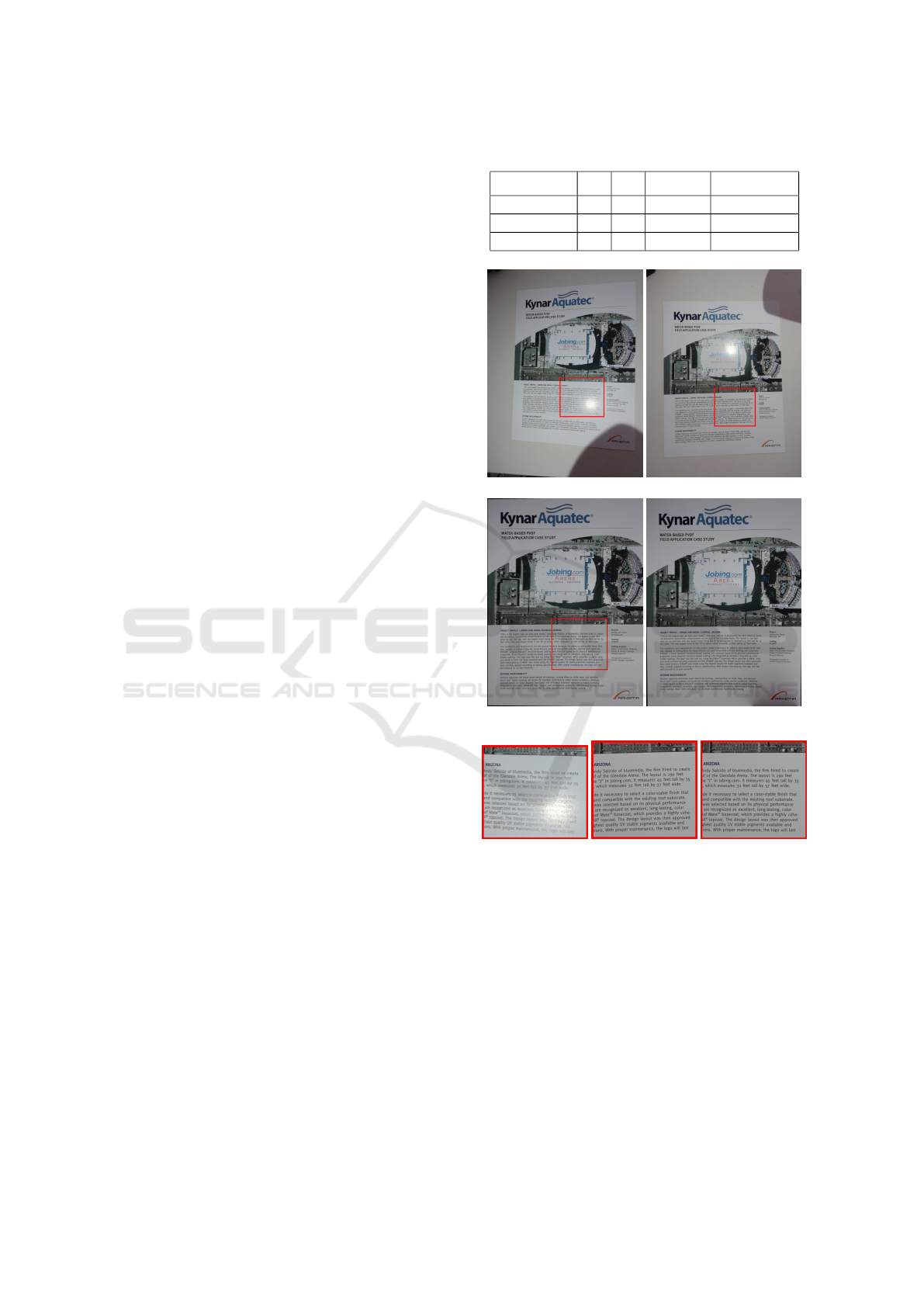
(a) Target image (b) Source image
(c) Corrected image (d) Corrected image with
automatic threshold
(e) Detail in target
image containing a
specular region
(f) Detail in source
image
(g) Detail in cor-
rected image
Figure 6: Automatic and manual thresholds for shadow de-
tection.
shadows and occlusions in target, source and cor-
rected images (denoted as T , S and C respectively).
All target images contained a specularity, while 13
of them additionally contained shadows. Occlusions
occurred in 14 of the target images. None of the ex-
amined image pairs contained phenomena occurring
in corresponding areas in both images.
The results of the experiments (summarized in Ta-
ble 1) show that the algorithm successfully detects
and removes the undesired phenomena for the ma-
VISAPP 2017 - International Conference on Computer Vision Theory and Applications
104

jority of the examined cases. With fully automatic
thresholds, we were able to remove 72% of all prob-
lematic regions. With user interaction, the problem-
atic regions were detected in all but one of the exam-
ined cases.
The method is especially successful in the removal
of specularities. Even in manual mode, the adjust-
ment of the automatically calculated threshold for
specularity detection was not usually required.
The proposed method is also successful in the de-
tection of shadows. The most challenging phenomena
are occlusions, because they may have very different
properties, and it is hard to reason about the source of
occlusion based on two views only. Figure 1 shows
an extreme case where the target image contains all
three kinds of degradations simultaneously. Never-
theless, all three problematic regions are successfully
repaired, the shadow is removed, the title which was
partially unreadable due to a strong highlight is re-
stored, and the occluded region is filled by the correct
information.
Another example is presented in Figure 6. Fig-
ure 6(c) shows the corrected image resulting from
a manual adjustment of the thresholds by the user.
On the other hand, Figure 6(d) depicts the result of
the algorithm if the thresholds are automatically de-
termined. The obtained corrected image is free of
the specularity, while the shadow is not correctly de-
tected and consequently not removed perfectly. Nev-
ertheless, the major part of the obtained result is visu-
ally consistent. Figures 6(e)-6(g) show details of the
target, source, and corrected image, respectively, de-
noted as red boxes in Figures 6(a)-6(c) and prove, that
the readability of the text is preserved.
The most severe problems of the proposed method
occur with shadows and occluding objects, when the
occurring phenomenon has similar intensity values to
the background. Such an example is shown in Fig-
ure 7, where the occluding object is detected and re-
moved only in the area with different color in the
background. Moreover, the shadow in Figure 7(a)
is not detected, because it lacks a distinct border and
rather presents a smooth intensity gradient in the im-
age. As a consequence, both effects partially remain
in the automatically computed corrected image (Fig-
ure 7(c)). If the thresholds are manually adjusted, the
effects can be minimized but not fully corrected (Fig-
ure 7(d)).
6 CONCLUSIONS
This paper proposes an algorithm that successfully
detects and removes specularities, shadows, and oc-
(a) Target image (b) Source image
(c) Corrected image with
automatic threshold
(d) Corrected image with
manual threshold
Figure 7: Case of undetected shadow and occlusion.
clusions using a two-frame technique for planar ob-
jects. Especially in the case of specular areas, the al-
gorithm performs very well. However, the algorithm
cannot detect shadows with very smooth borders or
occlusions with a color similar to the object. Ad-
ditionally, the algorithm can not remove phenomena
that occur in the same object region in both images.
Future work will fuse information from more images
which increases the likelihood to find an image re-
gion non-corrupted information. The automation of
the method should be increased by an robust proce-
dure to select corresponding thresholds.
REFERENCES
Artusi, A., Banterle, F., and Chetverikov, D. (2011). A
survey of specularity removal methods. In Computer
Graphics Forum, volume 30, pages 2208–2230. Wiley
Online Library.
Biasotti, S., Tarini, M., and Giachetti, A. (2015). Mobile
multiview diffuse texture extraction. In Smart Tools
and Applications in Computer Graphics, pages 113–
120. Eurographics Association.
Duch
ˆ
ene, S., Riant, C., Chaurasia, G., Lopez-Moreno, J.,
Laffont, P.-Y., Popov, S., Bousseau, A., and Drettakis,
G. (2015). Multi-view intrinsic images of outdoors
Specularity, Shadow, and Occlusion Removal for Planar Objects in Stereo Case
105

scenes with an application to relighting. ACM Trans-
actions on Graphics, page 16.
Feris, R., Raskar, R., Tan, K. H., and Turk, M. (2004). Spec-
ular reflection reduction with multi-flash imaging. In
Computer Graphics and Image Processing, Proceed-
ings of the 17th Brazilian Symposium, pages 316–321.
IEEE.
Fischler, M. A. and Bolles, R. C. (1981). Random sample
consensus: a paradigm for model fitting with appli-
cations to image analysis and automated cartography.
In Communications of the ACM, volume 24(6), pages
381–395.
Guo, R., Dai, Q., and Hoiem, D. (2011). Single-image
shadow detection and removal using paired regions.
In Computer Vision and Pattern Recognition (CVPR),
2011 IEEE Conference, pages 2033–2040. IEEE.
Klinker, G. J., Shafer, S. A., and Kanade, T. (1988). The
measurement of highlights in color images. Interna-
tional Journal of Computer Vision, 2(1):7–32.
Laffont, P.-Y., Bousseau, A., and Drettakis, G. (2013). Rich
intrinsic image decomposition of outdoor scenes from
multiple views. IEEE transactions on visualization
and computer graphics, 19(2):210–224.
Lin, S., Li, Y., Kang, S. B., Tong, X., and Shum, H. Y.
(2002). Diffuse-specular separation and depth recov-
ery from image sequences. In European conference
on computer vision, pages 210–224. Springer Berlin
Heidelberg.
Lowe, D. G. (2004). Distinctive image features from scale-
invariant keypoints. International journal of computer
vision, 60(2):91–110.
Ma, W. C., Hawkins, T., Peers, P., Chabert, C. F., Weiss, M.,
and Debevec, P. (2007). Rapid acquisition of specular
and diffuse normal maps from polarized spherical gra-
dient illumination. In In Proceedings of the 18th Euro-
graphics conference on Rendering Techniques, pages
183–194. Eurographics Association.
Mallick, S. P., Zickler, T., Belhumeur, P. N., and Krieg-
man, D. J. (2006). Specularity removal in images
and videos: A pde approach. In European Conference
on Computer Vision, pages 550–563. Springer Berlin
Heidelberg.
Murali, S. and Govindan, V. K. (2013). Shadow detec-
tion and removal from a single image using lab color
space. Cybernetics and information technologies,
13(1):95–103.
Nurutdinova, I., H
¨
ansch, R., M
¨
uhler, V., Bourou, S., and
Papadaki, A. I. (2016). Project Website. http://
www.rhaensch.de/specular.html.
Per
´
ez, P., Gangnet, M., and Blake, A. (2003). Poisson im-
age editing. In ACM Transactions on Graphics (TOG),
volume 22(3), pages 313–318. ACM.
Sun, J., Li, Y., Kang, S. B., and Shum, H. Y. (2005). Sym-
metric stereo matching for occlusion handling. In
2005 IEEE Computer Society Conference on Com-
puter Vision and Pattern Recognition (CVPR’05), vol-
ume 2, pages 399–406. IEEE.
van den Bergh, M., Boix, X., Roig, G., and van Gool,
L. (2015). Seeds: Superpixels extracted via energy-
driven sampling. International Journal of Computer
Vision (IJCV), 111(3):298–314.
Weiss, Y. (2001). Deriving intrinsic images from image se-
quences. In Computer Vision, 2001. ICCV 2001. Pro-
ceedings. Eighth IEEE International Conference on,
volume 2, pages 68–75. IEEE.
Yang, J., Liu, L., and Li, S. (2013). Separating specular and
diffuse reflection components in the hsi color space.
In Proceedings of the IEEE International Conference
on Computer Vision Workshops, pages 891–898.
Zitnick, C. L. and Kanade, T. (2000). A cooperative al-
gorithm for stereo matching and occlusion detection.
IEEE Transactions on pattern analysis and machine
intelligence, 22(7):675–684.
VISAPP 2017 - International Conference on Computer Vision Theory and Applications
106
