
Model Execution and Debugging
A Process to Leverage Existing Tools
Faiez Zalila
1,3
, Eric Jenn
1,∗
and Marc Pantel
2
1
IRT Antoine de Saint Exup
´
ery, Toulouse, France
2
IRIT, Universit
´
e de Toulouse, Toulouse, France
3
LAAS-CNRS, Universit
´
e de Toulouse, CNRS, Toulouse, France
Keywords:
Modeling, Formal Verification, Model-checking, Debugging, Simulation, Model Execution, IDE.
Abstract:
Model checking is an effective technique for the verification of critical systems. However, it relies on be-
havioral models which are costly to write and maintain. Thus, those models shall be validated and debugged
thoroughly, and simulation, i.e. model execution, can be used for that purpose. To reduce the development
costs of simulators and ensure their behavioral consistency with model verifiers, we advocate the reuse of
parts of the model verification tool-chain to implement them. To support this claim, this paper proposes a
method illustrated with a realistic case study applied to FIACRE behavioral models. The approach relies on
the creation and exploitation of relations between models representing the information required by the user on
the one hand, and information produced by the tools, on the other hand.
1 INTRODUCTION
1.1 Problem Statement
Early validation and verification (V&V) activities re-
duce development costs, as specification and design
errors can be detected and fixed as soon as possi-
ble in the development process. In that purpose,
these activities are performed on various system mod-
els (requirements, architecture, design, function, etc.)
expressed using various Domain Specific Modeling
Languages (DSMLs).
Whenever complex behavioral properties are at
stake, model-checking is an efficient approach to
prove the absence of errors on those models. How-
ever, to overcome scalability issues, it is usually
mandatory to create multiple models, at various ab-
straction levels, covering several kind of properties.
Animating those models is one of the best means
to remove trivial modeling bugs, to ensure that the
models indeed express the designers intents, and
eventually to reduce the overall cost of verification
(Bourdil et al., 2016b).
These models are defined using high-level lan-
guages that offer abstracts constructs. To be ver-
ified or validated, those models are usually trans-
∗
Seconded from Thales Avionics, Toulouse, France.
formed into lower level models conforming to the
more concrete formalisms used by model-checkers
and/or simulators (Visser et al., 2012). Then, to be
exploited, the runtime results produced by these tools
must be re-interpreted in terms of the initial abstract
language. Obviously, such round-trip between ab-
stract and concrete models could be avoided by devel-
oping V&V means directly applicable on abstract lan-
guages. However, we advocate the round-trip strategy
for two main reasons:
1. developing a new model checker or simulator and
ensuring the semantics consistency of those tools
is a very complex and costly task, and
2. there already exists a plethora of efficient model-
checkers and/or simulators.
Unfortunately, the necessary re-interpretation phase is
not trivial as information is lost during the successive
transformations to verification languages. In this pa-
per, we propose an approach to ease the implementa-
tion of the round-trip strategy based on the analysis of
annotated metamodels.
1.2 Our Contribution
Our approach combines and leverages existing low-
level verification, validation, and transformation
Zalila F., Jenn E. and Pantel M.
Model Execution and Debugging - A Process to Leverage Existing Tools.
DOI: 10.5220/0006143104010408
In Proceedings of the 5th International Conference on Model-Driven Engineering and Software Development (MODELSWARD 2017), pages 401-408
ISBN: 978-989-758-210-3
Copyright
c
2017 by SCITEPRESS – Science and Technology Publications, Lda. All rights reserved
401

means to provide the end-user with appropriate de-
bugging information. It relies on the construction of
relations between the data produced by the various
tools, and the user requirements for the model sim-
ulator.
We illustrate this approach on the development
of a model simulator for the FIACRE language
(Berthomieu et al., 2008) using the existing model
checking toolbox TINA (Berthomieu et al., 2004).
This paper is structured as follows. Section 2
presents the context of the study and the use-case.
It gives an overview of the user requirements for the
model simulator. Section 3 proposes and discusses
different design methods to develop the simulator.
Section 4 presents some related works in the domain
of simulators design. Section 5 concludes the paper.
2 THE CONTEXT AND THE
CASE-STUDY
The work presented in this paper is carried out in
the framework of the INGEQUIP project at the “In-
stitut de Recherche Technologique Saint-Exup
´
ery” at
Toulouse, France. This project experiments and as-
sesses innovative engineering methods and tools in
the domain of hardware/software co-design, virtual
integration and formal verification in the automotive,
space, and aeronautics domains.
The project demonstrator is a small three-wheeled
robot which architecture is representative of a signifi-
cant family of real systems. It is composed of a mis-
sion subsystem in charge of the computation of the
rover mission, trajectory tracking, etc. and a power
subsystem in charge of the management of the power-
train. The two subsystems are interconnected by a
unique CAN bus.
To comply with the availability and safety require-
ments, the mission subsystem is broken down into
two channels (left/right) with two units per channel
(COM/MON). A clock synchronization (CS) protocol
(Rodrigues et al., 1998) synchronizes all units.
This CS protocol model represents around 700
lines of FIACRE code, a high level verification lan-
guage used by several model checking tools. The
model covers both the units to be synchronized and
the communication network (CAN). Verification is
performed using the TINA tool-chain. Even though
directly inspired from (Rodrigues et al., 1998), build-
ing the model of the CS protocol required a signifi-
cant design and debugging effort due to the various
abstractions and simplifications that were required to
obtain a tractable model (Bourdil et al., 2016a). In
the rest of the document, we will take small excerpts
process Can
(&pai n , &pouts ,
&pkGM:MulPkts , &fp:nbFP, &fn:F N)
is
states rcv, txtime, tx, model _error
var m:Msg,
i:0..NB_NODES:=0,
fo:nbFO := 0,
omissions:Omissions : = init_omissions(),
omission:bool := false
from rcv
wait[0,0];
m := highestRankMsg(pktsIn);
on not (m.mtype=Empty);
to txtime
from txtime
wait [0.00005 , 0.000 05]; i := 0; to tx
from tx
wait [0,0];
select
on i < NB_NODES;
if not failedNode s[$i] then
pktsGammaMin[$i] :=
enqueue(pktsGammaMin[$i],m)
end;
i := i + 1;
loop
[]
on i < NB_NODES
and fo < FO and not fn[$i];
omissions[$i] := om issions[$i] + 1;
fo : = f o + 1;
m.omissions := m.omi ssions + 1;
omission := true;
if omissions[$i] = FO then
fp : = f p + 1; fn[$i] := true;
pkin[$i] := {||}; pkout[$i] := {||};
pkGM[$i] := {||}
end;
i := i + 1;
loop
[...]
Listing 1: FIACRE model of the CAN controller (extract).
of this model to illustrate specific issues encountered
during the design of the model simulator.
2.1 The FIACRE Modeling Language
FIACRE is the French acronym for Intermediate For-
mat for Embedded Distributed Component Architec-
tures. It was initially designed as the target language
for model transformations from different DSMLs
MODELSWARD 2017 - 5th International Conference on Model-Driven Engineering and Software Development
402

such as SDL (Rangra and Gaudin, 2014), AADL
(Berthomieu et al., 2010; Bodeveix et al., 2015) or
LADDER (Farines et al., 2011). FIACRE is used to
describe the behavioral and timing aspects of con-
current systems for formal verification and simulation
purposes. It is built around two mains constructs:
• Processes used to model sequential behaviors out
of states and transitions. A transition is associ-
ated with deterministic statements (assignments,
conditionals, loops, and sequential compositions),
non-deterministic choices, non-deterministic as-
signments and communication statements.
• Component modeling the hierarchical composi-
tion of processes.
Besides these two main constructs, FIACRE also sup-
ports the expression of properties involving FIACRE’s
observable elements (states, variables, etc.). The
property language includes LTL properties, Dwyer et
al. patterns and their timed extensions (Abid et al.,
2014).
Listing 1 shows a sample of the FIACRE code for
the clock synchronization model
1
. The elements used
later are in bold characters.
2.2 The TINA Verification Toolbox
Verifications are performed by the TINA toolbox, a
set of tools used to edit and analyze Timed Transition
System (TTS), an extension of Time Petri Nets (TPN)
with data manipulation. The following toolbox com-
ponents are considered in this paper:
• TINA constructs reachability graphs and Kripke
transitions systems from TTS and TPN
• PLAY animates TTS and TPN.
To be processed by TINA, a FIACRE model must
be translated to TTS using the dedicated tool FRAC
2
.
Due to the semantic gap between the two languages,
some information present in the FIACRE input may be
absent from the TTS output. Fortunately, FRAC gen-
erates traceability data that can be exploited to com-
pensate this loss. Now, let us consider the designers
needs in terms of debugging features.
2.3 Requirements for the FIACRE
Simulator
As stated before, even though verification is highly
automated thanks to model checking techniques,
1
The complete FIACRE model is accessible at
http://projects.laas.fr/fiacre/examples/2016-twirtee/twirtee/
claims/c1.fcr
2
http://projects.laas.fr/fiacre
building the model remains a manual activity. The
model developers require means to assess that the
model indeed expresses their intention and eliminate
modeling errors before starting the formal verification
phase (which might be quite costly). Moreover, after
the model checking phase, they also need means to
interpret the counter-examples that may be produced
by the model-checker.
To some extent, debugging models is similar to
debugging programs: users need capabilities to ob-
serve the sequences of states during the model execu-
tion, step through these sequences, stop the execution
when some condition occurs, etc.
date: 0
state 5: Ca n _1_s r c v , C a n _ 1_v s t a t e s =0 ,
Can_1_v m ={ mty p e = Adjust ,
nid = -1 ,
omissions =0 ,
ro u nd =0 , sid = -1} ,
Can_1_v i =0 , C a n _ 1 _ v fo =0 ,
Can _ 1 _ v om i s s i on s =[0 , 0 ,0] ,
Can _ 1 _ v omi s s i o n =false
enabled:
Can_1_t 0 [0 ,0]
Sta r t R o und _ 1 _ t 4 [0 , w [
. . .
firable: C a n _ 1 _ t 0
Sta r t R o und _ 1 _ t 4
. . .
? # 0
do firing: C a n _ 1 _ t 0
date: 0
state 6: Can _ 1 _ s t x time , C a n _ 1 _ v sta t e s =1 ,
Can_1_v m ={ mty p e = S tart ,
nid =0 ,
omissions =0 ,
ro u nd = -1 ,
sid =0} ,
Can_1_v i =0 , C a n _ 1 _ v fo =0 ,
Can _ 1 _ v om i s s i on s =[0 , 0 ,0] ,
Can _ 1 _ v omi s s i o n =false
enabled:
Can_1_t 1 [50 ,5 0]
Sta r t R o und _ 1 _ t 4 [0 , w [
. . .
firable: S t ar t R o u n d_ 1 _ t 4
Sta r t R o und _ 2 _ t 0
. . .
Listing 2: Excerpt of a TTS execution trace produced by the
TTS simulator (PLAY).
More precisely, it relates to debugging a multi-
threaded software since the execution of a FIACRE
model is the composition of multiple processes ex-
ecuted concurrently. However, some differences are
worth mentioning:
Model Execution and Debugging - A Process to Leverage Existing Tools
403
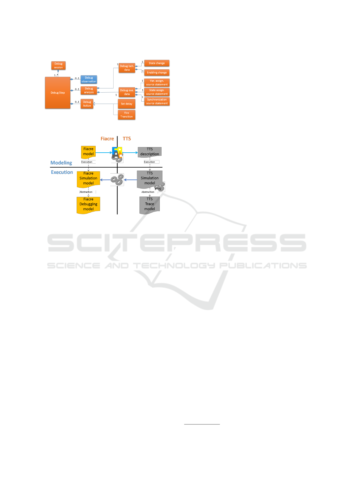
Figure 1: Informal debugging metamodel.
Figure 2: Technical domains.
1. the user has a full control of time,
2. some transitions within processes may be selected
non-deterministically (select clauses),
3. some state transitions may occur synchronously
between processes, etc.
While we concentrate on the particular example of
FIACRE in this paper, this is representative of struc-
tures and problems found with many other specifica-
tion languages like mCRL2 language (Cranen et al.,
2013) and AltaRica (Prosvirnova et al., 2013).
From now on, we focus on a few key requirements
for such an execution/debugging environment and see
how we managed to implement them with a minimal
development effort.
Let FS be the FIACRE Simulator under design.
REQ-1: The FS shall refer to modeling elements us-
ing user-level designation. For instance, it shall
present values according to the representation
used in the FIACRE source model. This applies
in particular to data types like structs, unions, etc.
REQ-2: When applicable, the FS shall display the
locations of modeling elements in the source
model. Reciprocally, the FS shall provide the user
with the capability to select or designate an ele-
ment directly on the source model.
REQ-3: The FS shall visualize the evolution of FI-
ACRE variables and states along time.
The previous list of requirements is (partially)
modeled on Figure 1: a debugging session is a se-
quence of debugging steps, each step being a triple
(observation, analysis, action) corresponding to the
usual scenario where: (1) the system is executed, (2)
some observations are obtained from this execution,
and (3) those observations determine the next step of
execution.
Of course, part of the triple may be ignored for
any execution step: observations may be ignored dur-
ing some specific phases (e.g., case of initialization),
actions may be automated (e.g., random selection of
transitions), etc.
In the rest of the document, focus is placed on the
Observation part (in blue on Figure 1). It is expanded
in Figure 2 where it is linked to the data provided by
the other available models.
3 DESIGN SOLUTIONS
Figure 2 shows the FIACRE and TTS technical do-
mains involved in the implementation. The execu-
tion information at the FIACRE level is obtained by
the analysis of the TTS simulation model. Listing 2
shows a sample of the TTS simulation model corre-
sponding to the CAN FIACRE process introduced ear-
lier. Figure 3 shows the three solutions that are pre-
sented and analyzed hereafter.
3.1 Solution 1: Use the TTS Simulation
Model
The first solution (the blue part at the top of Figure 3)
exploits two sources of information: the TTS descrip-
tion that represents the structure of a TTS model, and
the TTS simulation model (label 1 in Figure 3).
From these two sources, information about the ex-
ecution of the FIACRE model is obtained by a se-
quence of three phases: extraction, identification, and
construction.
Extraction consists in analyzing the textual out-
put of the PLAY tool to produce the TTS simulation
model. This phase is implemented using Xtext
3
.
Identification associates the TTS description ele-
ments with the FIACRE model elements. To do that,
some knowledge is required about: (1) how the TTS
desription is built from the FIACRE model, and (2)
how the FIACRE model elements are encoded is the
TTS description.
For example, state “txtime” of the first instance
of the CAN process declaration in FIACRE is encoded
3
https://www.eclipse.org/Xtext/
MODELSWARD 2017 - 5th International Conference on Model-Driven Engineering and Software Development
404
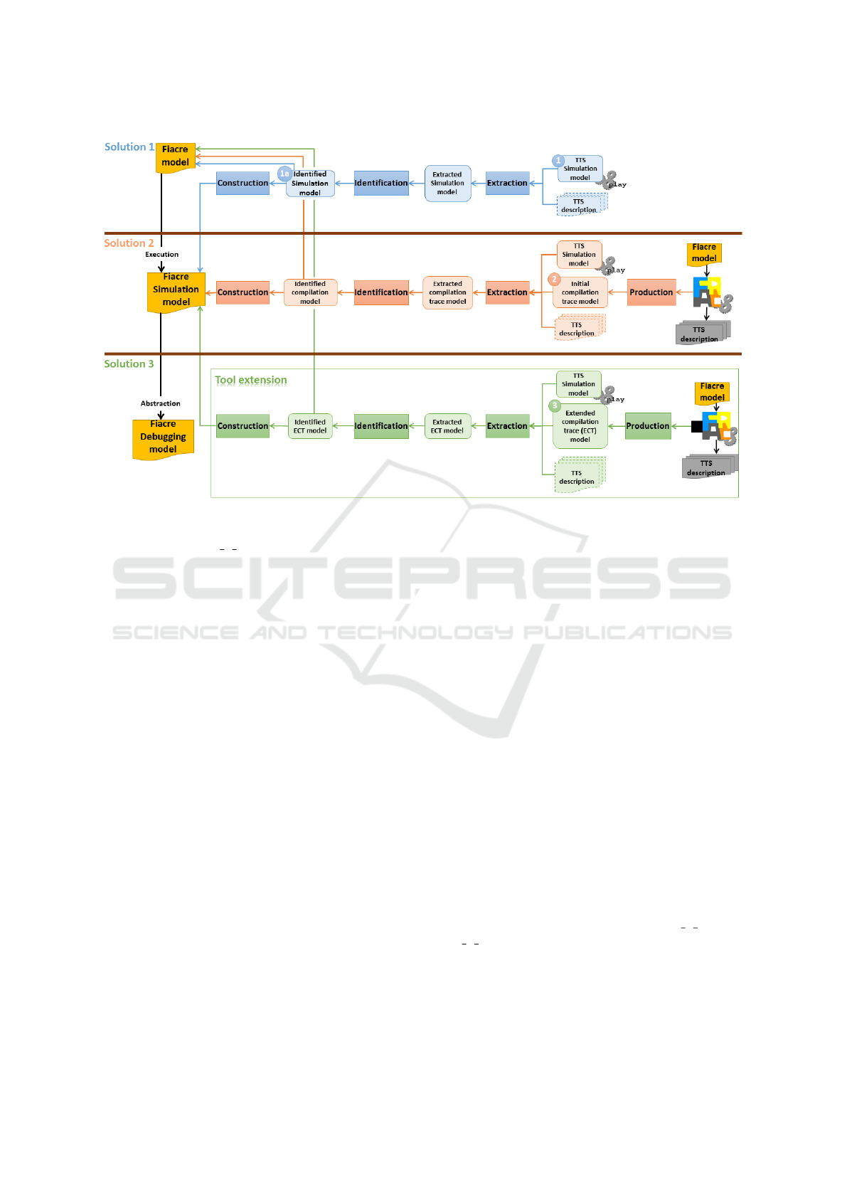
Figure 3: Implementation solutions.
as TTS place “Can 1 stxtime” (the “s” in the id
means that corresponds to a FIACRE state declara-
tion). Using this naming convention, one is able to
retrieve source elements from the FIACRE model.
Trans::Can_1_t0 & Ma in
from Can_1_srcv
on ({Can_1_vm :=
highestRankMsg (Main_1_vpktsOut);
not((Can_1_vm.mtype = Empty))});
Can_1_vm :=
highestRankMsg (Main_1_vpktsOut);
Can_1_vstates := 1;
to Can_1_stxtime
in [0,0]
Trans::Can_1_t1 & Ma in
from Can_1_stxtime
on true;
Can_1_vi := 0;
Can_1_vstates := 2;
to Can_1_stx
in [50,50]
Listing 3: Excerpt of the initial compilation trace model.
Finally, Construction produces the simulation in-
formation at FIACRE level by instantiating the ap-
propriate elements of the FIACRE simulation meta-
model using the Identified Simulation Model (label
1a in Figure 3). Unfortunately, this first solution only
complies with user requirement REQ-3 due to miss-
ing data in the TTS description and TTS Simulation
model. This lack is caused by the multiple optimiza-
tions performed during the compilation phase by the
FRAC compiler. So, let us consider the second solu-
tion.
3.2 Solution 2: Use Traceability Data
Solution 2 (in red in Figure 3) extends solution 1
by combining the TTS simulation model (see List-
ing 2) with initial compilation trace model generated
by FRAC (-G option) (label 2 in Figure 3).
Historically, this information was used for de-
bugging purposes during the development of FRAC.
Later, it was also used to feed verification results from
the TTS level back to FIACRE (Zalila et al., 2012;
Zalila et al., 2013). It is produced during the last step
of the translation phase, before the generation of the
TTS description. It contains TPN and data processing
constructs (guards, assignments, etc.).
Listing 3 shows a subset of a compilation trace
model related to the CAN process shown in Listing1.
It contains two TTS transitions: Can 1 t0 and
Can 1 t1. In order to locate these transitions in the
FIACRE source model using the initial compilation
trace model, it is necessary to understand how the
FRAC compiler generates TTS identifiers from FI-
ACRE-level identifiers.
Once this relation is established, the transitions
Model Execution and Debugging - A Process to Leverage Existing Tools
405

are immediately located in the source code. For ex-
ample, transition “Can 1 t0”, which identifiers ends
with “t0”, corresponds to the first transition on the
first instance of a CAN process (see lines 9-13 in List-
ing 1). Similarly, transition “Can 1 t1” corresponds
to the transition located at lines 14-16 in Listing 1.
Syntactic and semantic analysis are required to
identify the corresponding TTS model elements. Syn-
tactic analysis raises no particular difficulty. Semantic
analysis can be achieved in two ways. First, the transi-
tion body may be analyzed line-by-line. This solution
requires a significant effort and in-depth knowledge
on the internals of FRAC.
"flatname": "Can_1",
2 "inst": 1,
"l oc":
4 {"from": {"char": 0, "line": 270},
"to": { "char": 0, "line": 364}},
6 "name": "Can ",
"states": [
8 {"fl atname": "Can_ 1_srcv",
"l oc":
10 {"from": {"char": 7, "line": 272},
"to": { "char": 10, "line": 272}},
12 "sourcename": "rcv"},
...
14 ],
"transitions": [
16 ...
{"locations": [
18 {"from": {"char": 0, "line": 288},
"to": { "char": 11, "line": 288}},
20 {"from": {"char": 2, "line": 290},
"to": { "char": 25, "line": 290}},
22 {"from": {"char": 25, "line": 290},
"to": { "char": 8, "line": 292}},
24 {"from": {"char": 2, "line": 293},
"to": { "char": 0, "line": 295}}
26 ],
"name": "Can_1_t1"
28 },
...
30 ],
...
Listing 4: Excerpt of the ECT model.
For example, FRAC sometimes adds internal guards
(e.g., guard on true for transition Can 1 t1), en-
riches existing guards (e.g., guard of transition
Can 1 t0), adds internal assignments, replaces con-
stant identifiers by their value, etc.
Second, the index given in the transitions identi-
fiers (t0, t1, t2, etc.) may be used as the rank of the
transition in the source code of the process.
However, the presence of nested non-
deterministic constructs containing quite similar
source code makes this task extremely difficult.
Moreover, this solution satisfies user requirement
REQ-2 only partially as it fails to reach the source
code level. To overcome this problem, we rely on the
extended compilation trace (ECT) model.
3.3 Solution 3: Use the ECT Model
Solutions 1 and 2 have not succeeded to satisfy all
user requirements. Used as black-boxes, the existing
tools do not provide sufficient information to asso-
ciate unequivocally the FIACRE model elements with
the TTS model elements: information is so degraded
that this association cannot be reconstructed. The last
proposal is then to extend the FRAC tool in order
to export the information lost in translation. Accord-
ingly, we introduce a new trace model, called “Ex-
tended Compilation Trace” (ECT) model (label 3 in
Figure 3), that is generated when the option “j” of
FRAC is activated.
The ECT model offers a direct mapping between
the FIACRE source code elements and the correspond-
ing constructs in the TTS model. The structure of the
ECT reflects the hierarchical organization of the FI-
ACRE model. Listing 4 shows a subset of the gener-
ated ECT model related to the CAN process. In this
example, lines 8-12 associate the generated TTS place
identifier Can 1 srcv with its corresponding FIACRE
source code (sourcename) and its location (character
10 on line 272). This information allows retrieving
the FIACRE source code information directly from the
TTS. Finally, the path from the TTS model to the de-
bugging model is complete, as shown on Figure 4: all
user requirements are satisfied.
3.4 Comparison of Solutions
In this subsection, we compare the previous solutions
by estimating the cost required to recover information
degraded during the compilation phase. Figure 4 il-
lustrates this process. In this example, we consider a
FIACRE source code containing a process, proc, in-
stantiated in the compo component. The proc process
has a transition containing a non-deterministic state-
ment. The first choice has an assignment, x:=x+1,
followed by a jump statement to s1 state. The sec-
ond choice has an assignment, x:=x+2, followed by
a jump statement to s1 state. Let us consider the fol-
lowing user requirements:
REQ-2a: the FS shall display the executed FIACRE
statements.
REQ-2b: the FS shall display the executed FIACRE
statements in the source model.
MODELSWARD 2017 - 5th International Conference on Model-Driven Engineering and Software Development
406
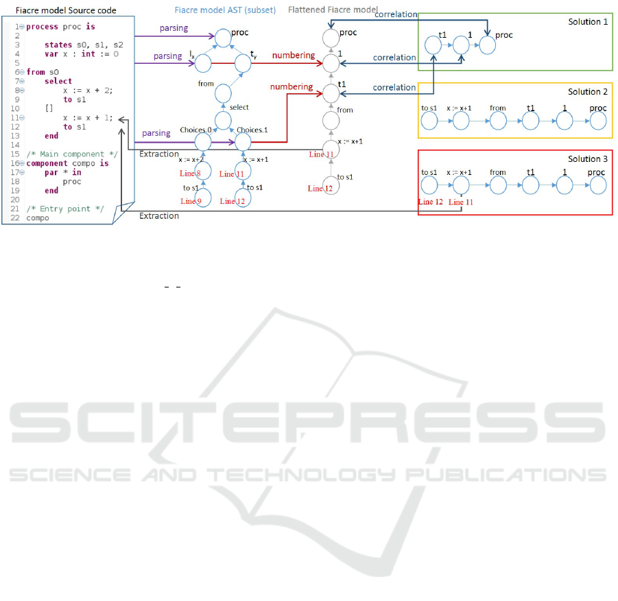
Figure 4: Assessing solutions.
The problem consists in satisfying those requirements
when the TTS transition proc 1 t1 is fired during an-
imation.
First, we generate the abstract syntax tree (AST)
of the FIACRE model using Xtext. This AST is
flattened in order to generate the TTS transitions.
Flattening consists in assigning an identifier number
to each component/process instance according to its
rank in the container component. A similar flatten-
ing activity is performed on the choices of the non-
deterministic statements in order to generate the body
of each TTS transition. As shown on Figure 4, The
flattened FIACRE model represents a pivot model be-
tween the FIACRE and TTS levels.
To satisfy REQ-a, solution 1 consists in complet-
ing the parsing and numbering activities by correlat-
ing the different available information (proc, 1 and
t1) to the generated ones in the flattened FIACRE
model. This process allows identifying the concerned
TTS transition and thus extracting the corresponding
statements. Moreover, as the source code informa-
tion (Line 6, Line 11, etc.) is already available in the
identified TTS transition after the parsing, numbering,
correlation and extracting activities, satisfying REQ-a
and REQ-b represent the same costs.
For solution 2, the cost to satisfy REQ-a is negli-
gible because the text of the executed FIACRE state-
ments are already available in the TTS transition.
However, the cost to satisfy REQ-b is the same as for
solution 1.
For solution 3, the cost to satisfy all requirements
is negligible because the new generated traceability
information is sufficient to identify the related infor-
mation at the source code level.
Therefore, solution 3 is adopted now to develop an
integrated development environment for the FIACRE
language because it can satisfy all end-user require-
ments on the one hand, and it represents the lowest
cost to resolve FIACRE to TTS mappings on the other.
4 RELATED WORKS
Language engineering tool-sets target the modeling of
languages and the implementation of associated tools
but the behavioral concerns are usually not handled.
More recent toolsets, like xCore, xMOF (Mayerhofer
et al., 2013), the K framework (Rosu, 2013) or the
GEMOC studio (Combemale et al., 2016) allow to
handle it and ease the development of model simu-
lators. However, they usually do not target model
checkers except the K framework. But, this one do not
allow to manage efficiently the combinatorial explo-
sion of concurrent behaviors and thus does not scale
to many realistic models. We could have used these
tool-sets to build the FIACRE simulator. Moreover,
this could lead to semantic inconsistencies between
the behavior considered in the model checker and the
behavior considered in the simulator. Thus we de-
cided to study the reuse of parts of the model checker
to ensure the same behavior in the simulator.
In the literature, exploiting low-level simulation
information to feedback it into the end-user level is
usually neglected. For example, in the context of the
AltaRica project (Prosvirnova et al., 2013), models
are compiled into a low level formalism: Guarded
Transition Systems (GTS). In this project, the step-
wise simulator performs an interactive step by step
simulation on the generated GTS model. For the
mCRL2 toolset (Cranen et al., 2013), a mCRL2 spec-
ification is transformed into a linear process specifi-
cation on which the simulation activity is performed.
Model Execution and Debugging - A Process to Leverage Existing Tools
407

5 CONCLUSION AND FUTURE
WORK
In this paper, we have shared our experience about
reusing existing low-level formal verification and val-
idation tools in order to provide model simulation ca-
pabilities to the end-user. It consists on producing dy-
namic information on the HLL based on runtime in-
formation generated on the LLL. This work enabled
us to develop a FIACRE simulator which is the result
of a long research to hide all TTS information to the
FIACRE end-user during the animation of his model.
This work has resulted in the implementation of a FI-
ACRE simulator tool
4
This is part of an ongoing work
to develop a complete FIACRE IDE that will eventu-
ally integrate advanced features of model animation
like the guided-simulation and the multi-branch sim-
ulation.
REFERENCES
Abid, N., Dal Zilio, S., and Le Botlan, D. (2014). A formal
framework to specify and verify real-time properties
on critical systems. Int. J. Crit. Comput.-Based Syst.,
5(1/2):4–30.
Berthomieu, B., Bodeveix, J.-P., Dal Zilio, S., Dissaux, P.,
Filali, M., Gaufillet, P., Heim, S., and Vernadat, F.
(2010). Formal Verification of AADL models with
FIACRE and TINA. In ERTSS 2010 , pages 1–9,
Toulouse, France.
Berthomieu, B., Bodeveix, J.-P., Filali, M., Farail, P., Gau-
fillet, P., Garavel, H., and Lang, F. (2008). FIACRE: an
Intermediate Language for Model Verification in the
TOPCASED Environment. In 4
th
European Congress
ERTS Embedded Real-Time Software (2008).
Berthomieu, B., Ribet, P.-O., and Vernadat, F. (2004). The
tool TINA – Construction of Abstract State Spaces for
Petri Nets and Time Petri Nets. International Journal
of Production Research, 42(14):2741–2756.
Bodeveix, J.-P., Filali, M., Garnacho, M., Spadotti, R., and
Yang, Z. (2015). Towards a verified transformation
from AADL to the formal component-based language
FIACRE. Science of Computer Programming, 106:30
– 53. Special Issue: Architecture-Driven Semantic
Analysis of Embedded Systems.
Bourdil, P.-A., Dal Zilio, S., and Jenn, E. (2016a). Integrat-
ing Model Checking in an Industrial Verification Pro-
cess: a Structuring Approach. LAAS report n
◦
16115.
https://hal.archives-ouvertes.fr/hal-01341701.
Bourdil, P.-A., Jenn, E., and Dal Zilio, S. (2016b). Build-
ing Confidence on Formal Verification Models. In
Fast Abstracts at International Conference on Com-
puter Safety, Reliability, and Security (SAFECOMP),
Trondheim, Norway.
4
A demo of the simulator can be found here
http://projects.laas.fr/fiacre/ide/demo.mov
Combemale, B., Brun, C., Champeau, J., Cr
´
egut, X., Dean-
toni, J., and Le Noir, J. (2016). A Tool-Supported
Approach for Concurrent Execution of Heterogeneous
Models. In 8th European Congress on Embedded Real
Time Software and Systems (ERTS 2016), Toulouse,
France.
Cranen, S., Groote, J. F., Keiren, J. J. A., Stappers, F. P. M.,
de Vink, E. P., Wesselink, W., and Willemse, T. A. C.
(2013). An Overview of the mCRL2 Toolset and Its Re-
cent Advances, pages 199–213. Springer Berlin Hei-
delberg, Berlin, Heidelberg.
Farines, J.-M., De Queiroz, M. H., De Rocha, V., Carpes,
A. M., Vernadat, F., and Cr
´
egut, X. (2011). A Model-
Driven Engineering Approach to Formal Verification
of PLC programs (regular paper). In Emerging Tech-
nologies and Factory Automation (ETFA), Toulouse,
France, pages 1–8. IEEE.
Mayerhofer, T., Langer, P., Wimmer, M., and Kappel,
G. (2013). xMOF: Executable DSMLs Based on
fUML, pages 56–75. Springer International Publish-
ing, Cham.
Prosvirnova, T., Batteux, M., Brameret, P.-A., Cherfi, A.,
Friedlhuber, T., Roussel, J.-M., and Rauzy, A. (2013).
The AltaRica 3.0 project for model-based safety as-
sessment. IFAC Proceedings Volumes, 46(22):127 –
132.
Rangra, S. and Gaudin, E. (2014). SDL to FIACRE trans-
lation. In Embedded Real-Time Software and Systems
(ERTS 2014).
Rodrigues, L., Y, M. G., and Rufino, J. (1998). Fault-
tolerant clock synchronization in can. In In Proc. of
the 19th Real-Time Systems Symposium (RTSS, pages
420–429. IEEE Computer Society Press.
Rosu, G. (2013). Specifying languages and verifying pro-
grams with k. In Proceedings of 15th International
Symposium on Symbolic and Numeric Algorithms
for Scientific Computing (SYNASC’13), IEEE/CPS.
IEEE.
Visser, W., Dwyer, M. B., and Whalen, M. (2012). The Hid-
den Models of Model Checking. Software & Systems
Modeling, 11(4):541–555.
Zalila, F., Cr
´
egut, X., and Pantel, M. (2012). Verification
results feedback for FIACRE intermediate language. In
Conf
´
erence en Ing
´
enierie du Logiciel (CIEL).
Zalila, F., Cr
´
egut, X., and Pantel, M. (2013). Formal veri-
fication integration approach for DSML. In Moreira,
A., Sch
¨
atz, B., Gray, J., Vallecillo, A., and Clarke,
P., editors, Model-Driven Engineering Languages and
Systems, volume 8107 of Lecture Notes in Computer
Science, pages 336–351. Springer Berlin Heidelberg.
MODELSWARD 2017 - 5th International Conference on Model-Driven Engineering and Software Development
408
