
Model-Driven Performance Evaluation and Formal Verification for
Multi-level Embedded System Design
Daniela Genius
1
, Letitia W. Li
2
and Ludovic Apvrille
2
1
Sorbonne Universit
´
es, UPMC Paris 06, LIP6, CNRS UMR 7606, Paris, France
2
T
´
el
´
ecom ParisTech, Universit
´
e Paris-Saclay, Biot, France
Keywords:
Virtual Prototyping, Embedded Systems, System-level Design, Formal Verification.
Abstract:
The design methodology of an embedded system should start with a system-level partitioning dividing func-
tions into hardware and software. However, since this partitioning decision is taken at a high level of ab-
straction, we propose regularly validating the selected partitioning during software development. The paper
introduces a new model-based engineering process with a supporting toolkit, first performing system-level
partitioning, and then assessing the partitioning choices thus obtained at different levels of abstraction dur-
ing software design. This assessment shall in particular validate the assumptions made on system-level (e.g.
on cache miss rates) that cannot be precisely determined without low-level hardware model. High-level parti-
tioning simulations/verification rely on custom model-checkers and abstract models of software and hardware,
while low-level prototyping simulations rely on automatically generated C-POSIX software code executing on
a cycle-precise virtual prototyping platform. An automotive case study on an automatic braking application
illustrates our complete approach.
1 INTRODUCTION
Embedded systems are composed of a tightly in-
tegrated ensemble of HW and SW components.
The design of these systems usually starts with a
system-level partitioning phase, continues with sep-
arate software and hardware design, and finishes with
a HW/SW integration. In fact, this integration can
also be performed progressively during software de-
sign using prototyping techniques.
At system-level partitioning, properties of em-
bedded applications can be tested rapidly and their
description remains somewhat “human-readable”.
Properties can also be proven formally. Exploration,
however, remains at a rather abstract level e.g. many
hardware parameters are approximated. For example,
the cache miss rate is modeled as a fixed value (e.g.,
5%) obtained from the architect’s experience.
After partitioning, software is designed at lower
abstraction levels. Commonly, the hardware target is
not available, leading to the use of simulation tech-
niques with precise hardware models. System pa-
rameters, such as the cache miss ratio, can be closely
evaluated with simulations and formal proofs. Unfor-
tunately, more details also means much slower sim-
ulations, and infeasible formal proofs, even if com-
positional approaches could help handle entire hard-
ware platforms. However, they are costly (Basu et al.,
2011; Syed-Alwi et al., 2013) in terms of develop-
ment time.
To improve both development stages (partitioning,
prototyping), we propose to unify them in a common
SysML formalism. In fact, prototyping can rely on
software and hardware elements that were formally
evaluated at partitioning. Partitioning models can be
enhanced using precise parameters that can be ob-
tained during simulation at the prototyping level. Our
toolkit, TTool (Apvrille, 2015), supports both stages,
and makes it possible, at the push of a button, to eval-
uate the design at a given development stage, and to
propagate the results to enhance the system at an-
other development state, thus easing development it-
erations. We previously described (Li et al., 2016) our
approach towards multi-level Design Space Explo-
ration, but without the ability to generate detailed per-
formance metrics during prototyping that we present
in this paper.
Section 2 presents related work. Section 3
presents the overall design method. Section 4 details
an automotive case study used to exemplify the high-
level design space exploration (Section 5), as well as
software component design and performance evalua-
78
Genius D., W. Li L. and Apvrille L.
Model-Driven Performance Evaluation and Formal Verification for Multi-level Embedded System Design.
DOI: 10.5220/0006140600780089
In Proceedings of the 5th International Conference on Model-Dr iven Engineering and Software Development (MODELSWARD 2017), pages 78-89
ISBN: 978-989-758-210-3
Copyright
c
2017 by SCITEPRESS – Science and Technology Publications, Lda. All rights reserved

tion (Section 6). A final discussion and perspectives
on future work are presented in Section 7.
2 SYSTEM-LEVEL DESIGN FOR
EMBEDDED SYSTEMS
A number of system-level design tools exist, offering
a variety of verification and simulation capabilities at
different levels of abstraction.
Ptolemy (Buck et al., 2002) proposes a modeling
environment for the integration of diverse execution
models, in particular hardware and software compo-
nents. If design space exploration can be performed
with Ptolemy, its first intent is the simulation of the
modeled systems.
Metropolis (Balarin et al., 2003) targets hetero-
geneous systems, and architectural and application
constraints are closely interwoven. This approach is
more oriented towards application modeling, even if
hardware components are closely associated to the
mapping process. While our approach uses Model-
Driven Engineering, Metropolis uses Platform-Based
Design.
Sesame (Erbas et al., 2006) proposes modeling
and simulation features at several abstraction lev-
els for Multiprocessor System-on-Chip architectures.
Pre-existing virtual components are combined to form
a complex hardware architecture. Models’ semantics
vary according to the levels of abstraction, ranging
from Kahn process networks (KPN (Kahn, 1974)) to
data flow for model refinement, and to discrete events
for simulation. Currently, Sesame is limited to the
allocation of processing resources to application pro-
cesses. It models neither memory mapping nor the
choice of the communication architecture.
The ARTEMIS (Pimentel et al., 2001) project is
strongly based on the Y-chart approach. Application
and architecture are clearly separated: the application
produces an event trace at simulation time, which is
read by the architecture model. However, behavior
depending on timers and interrupts cannot be taken
into account.
MARTE (Vidal et al., 2009) shares many com-
monalities with our approach, in terms of the ca-
pacity to separately model communications from the
pair application-architecture. However, it intrinsically
lacks a separation between control and message ex-
change.
Other works based on UML/MARTE, such as
Gaspard2 (Gamati
´
e et al., 2011), are dedicated to both
hardware and software synthesis, relying on a refine-
ment process based on user interaction to progres-
sively lower the level of abstraction of input models.
However, such a refinement does not completely sep-
arate the application (software synthesis) or architec-
ture (hardware synthesis) models from communica-
tion.
Rhapsody can automatically generate software,
but not hardware descriptions from SysML. MDGen
from Sodius (Sodius Corporation, 2016) adds tim-
ing and hardware specific artifacts such as clock/reset
lines automatically to Rhapsody models, generates
synthesizable, cycle-accurate SystemC implementa-
tions, and automates exploration of architectures.
The Architecture Analysis & Design Language
AADL (Feiler et al., 2004) allows the use of formal
methods for safety-critical real-time systems. Simi-
lar to our environment, a processor model can have
different underlying implementations and its charac-
teristics can easily be changed at the modeling stage.
Recently, (Yu et al., 2015) developed a model-based
formal integration framework which endows AADL
with a language for expressing timing relationships.
Capella (Polarsys, 2008) relies on Arcadia, a com-
prehensive model-based engineering method. It is in-
tended to check the feasibility of customer require-
ments, called needs, for very large systems. Capella
provides architecture diagrams allocating functions to
components, and advanced mechanisms to model bit-
precise data structures.
3 METHODOLOGY
3.1 Modeling Phases
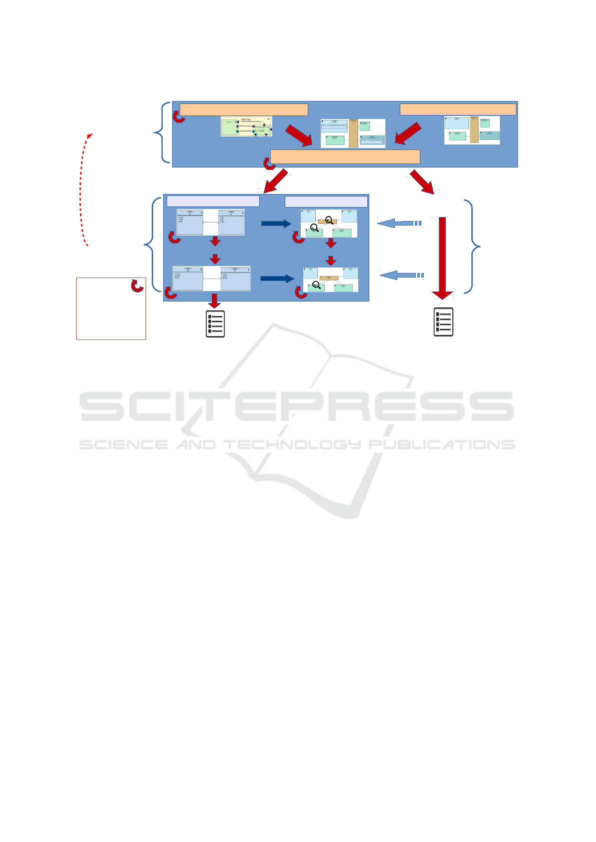
Our approach combines partitioning - the partitioning
decision relies on design space exploration techniques
- and software design. The latter includes the proto-
typing of the designed software. All stages are sup-
ported within the same SysML-based free and open-
source environment/toolkit (as shown in Figure 1):
1. The overall method starts with a partitioning
phase containing three sub-phases: the modeling
of the functions to be realized by the system (func-
tional view), the modeling of the candidate archi-
tecture as an assembly of highly abstracted hard-
ware nodes, and the mapping phase. A function
mapped on a processor is a software function, a
function mapped on a hardware accelerator cor-
responds to a custom ASIC (Application-specific
Integrated Circuit).
2. Once the system is fully partitioned, the second
phase starts with the design of the software and
the hardware. Our approach offers software mod-
eling while taking into account hardware parame-
Model-Driven Performance Evaluation and Formal Verification for Multi-level Embedded System Design
79
Final
software
code
Refinements
VHDL/Verilog
Software
Design and
Prototyping
(AVATAR)
Deployment view
...
...
Hardware
design
Abstractions
Abstractions
Reconsideration
of partitioning
decisions
Simulation
and
Verification :
safety, security
and
performance
Mapping view
Functional view
Architecture view
Software Component
Hardware
model
Partitioning
with
Design Space
Exploration
techniques
(DIPLODOCUS)
Figure 1: Overall Approach.
ters for prototyping purposes. Thus, a deployment
view displays how the software components are
allocated to the hardware components. Code can
then be generated both for the software compo-
nents of the application (in C/POSIX code) and
for the virtual hardware nodes (in SoCLib (So-
CLib consortium, 2010) System C format).
Choice of parameters on the higher level is subject to
validation or invalidation due to experimental results
on the generated prototype. Thus, simulations results
at prototyping level could lead to reconsider the parti-
tioning decisions.
3.2 Simulation, Verification and
Prototyping
During the methodological phases, simulation and
formal verification help in deciding whether safety,
performance and security requirements are fulfilled.
Our toolkit offers a press-button approach for per-
forming these proofs. Model transformations trans-
late the SysML models into an intermediate form that
is sent into the underlying simulation and formal ver-
ification utilities. Backtracing to models is then per-
formed to better inform the users about the verifica-
tion results. Proofs of safety involve UPPAAL seman-
tics (Bengtsson and Yi., 2004), and security proofs
use ProVerif (Blanchet, 2010). Before the next stage,
simulation and formal verification ensure that our de-
sign meets performance, behavioral, and schedulabil-
ity requirements. Simulation of partitioning specifi-
cations involves executing tasks on the different hard-
ware elements in a transactional high-level way. Each
transaction executes for a variable time depending on
execution cycles and CPU parameters. The simula-
tion shows performance results like bus usage, CPU
usage, execution time, etc., so as to help users de-
cide on an architecture and mapping. For example,
singles execution sequences can be investigated with
gtkwave. Also, our toolkit assists the user by automat-
ically generating all possible architectures and map-
pings, and summarizes performance results of each
possible mapping. Users are provided with the “best”
architecture under specified criteria, such as minimal
latency or bus/CPU load.
During functional modeling, verification intends
to identify general safety properties (e.g., absence of
deadlock situations). At the mapping stage, verifi-
cation intends to ascertain if performance and secu-
rity requirements are met. Hardware components are
highly abstracted. For example, a CPU can be de-
fined with a set of parameters such as an average
cache-miss ratio, power-saving mode activation, con-
text switch penalty, etc.
After mapping, software components can also be
verified independently of any hardware architecture
in terms of safety and security. For example, when
designing a component implementing a security pro-
tocol, the reachability of the states and absence of se-
curity vulnerabilities can be verified. When the soft-
ware components become more refined, it becomes
MODELSWARD 2017 - 5th International Conference on Model-Driven Engineering and Software Development
80
<<CPURR>>
CPU_CU
Braking - FV::DSRCManagement
Braking - FV::CorrectnessChecking
Braking - FV::CorrectnessChecking
Braking - FV::NeighbourhoodTableManagement
Braking - FV::NeighbourhoodTableManagement
<<HWA>>
PTC_Devices
Braking - FV::doReduceDrivingPower
Braking - FV::doReduceDrivingPower
<<CPURR>>
CPU_PTC
Braking - FV::DrivingPowerReductionstrategy
Braking - FV::DrivingPowerReductionstrategy
<<MEMORY>>
Flash_PTC
<<BUS-RR>>
CAN_CU
<<MEMORY>>
RAM_PTC
<<BUS-RR>>
CAN_CSCU
<<BRIDGE>>
CSCU_to_CAN
<<BRIDGE>>
PTC_to_CAN
<<MEMORY>>
Flash_CSCU
<<MEMORY>>
Flash_BCU
<<HWA>>
UMTS
<<HWA>>
DSRC
Braking - FV::DSRCRxTx
<<MEMORY>>
Flash_CU
<<BUS-RR>>
CAN_CU
<<BRIDGE>>
CU_to_CAN
<<BUS-RR>>
CAN
<<CPURR>>
CPU_CSCU
Braking - FV::ObjectListManagement
Braking - FV::ObjectListManagement
Braking - FV::PlausibilityCheck
Braking - FV::PlausibilityCheck
Braking - FV::VehicleDynamicsManagement
Braking - FV::VehicleDynamicsManagement
<<MEMORY>>
RAM_CSCU
<<HWA>>
ChassisSensors
Braking - FV::GetVehicleDynamics
Braking - FV::GetVehicleDynamics
<<HWA>>
EnvSensors
Braking - FV::GetEnvironmentInformation
Braking - FV::GetEnvironmentInformation
<<BRIDGE>>
BCU_to_CSCU
<<BUS-RR>>
CAN_BCU
<<CPURR>>
CPU_BCU
Braking - FV::DangerAvoidanceStrategy
Braking - FV::DangerAvoidanceStrategy
Braking - FV::BrakeManagement
Braking - FV::BrakeManagement
<<MEMORY>>
RAM_BCU
<<HWA>>
BrakingControlDevice
Braking - FV::DoBrake
Braking - FV::DoBrake
<<HWA>>
GPS
Braking - FV::GPSReception
<<MEMORY>>
RAM_CU
Figure 2: Automotive Case Study Architecture Diagram.
important to evaluate their performance when exe-
cuted on the target platform. Since the target sys-
tem is commonly not yet available, our approach of-
fers two facilities: a Deployment Diagram in which
software components can be mapped over hardware
nodes (see Figure 4), and a press-button approach to
transform this Deployment Diagram into a specifica-
tion built upon virtual component models. For this,
we use SoCLib, a public domain library of component
models written in SystemC. SoCLib targets shared-
memory multiprocessor-on-chip system (MP-SoC) ar-
chitectures based on the Virtual Component Intercon-
nect (VCI) protocol (VSI Alliance, 2000) which sep-
arates the components’ functionality from commu-
nication. Hardware is described at several abstrac-
tion levels: TLM (Transaction level), CABA (Cy-
cle/Bit Accurate), and RTL (Register Transfer Level).
SoCLib also contains a set of performance evalua-
tion tools (Genius et al., 2011). Last but not least,
the SoCLib prototyping platform comes with an oper-
ating system well adapted to multiprocessor-on-chip
(Becoulet, 2009).
If the performance results of the SystemC simula-
tion differ too greatly from the ones obtained during
the design space exploration stage – e.g., a cache miss
ratio – then, design space exploration shall be per-
formed again to assess if the selected architecture is
still the best according to the system requirements. If
not, software components may be (re)designed. Once
the iterations over the high-level design space explo-
ration and the low level virtual prototyping of soft-
ware components are finished, software code can be
generated from the most refined software model.
4 AUTOMOTIVE CASE STUDY
Our methodology is illustrated using an automotive
embedded system designed in the scope of the Eu-
ropean EVITA project (EVITA, 2011). Recent on-
board Intelligent Transport (IT) architectures com-
prise a very heterogeneous landscape of communica-
tion network technologies (e.g., LIN, CAN, MOST,
and FlexRay) that interconnect in-car Electronic Con-
trol Units (ECUs).
The increasing number of such equipment trig-
gers the development of novel applications that are
commonly spread among several ECUs to fulfill their
goals. Prototyping on multiprocessor architectures,
even if they are more generic than the final hardware,
is thus very useful.
An automatic braking application serves as a case
study (Kelling et al., 2009). The system works essen-
tially as follows: an obstacle is detected by another
automotive system which broadcasts that information
to neighboring cars. A car receiving such informa-
tion has to decide if it is concerned with this obstacle.
This decision includes a plausibility check function
that takes into account various parameters, such as the
direction and speed of the car, and also information
previously received from neighboring cars. Once the
decision to brake has been taken, the braking order
is forwarded to relevant ECUs. Also, the presence of
this obstacle is forwarded to other neighboring cars in
case they have not yet received this information.
The stages of the methodology include Partition-
ing by Design Space Exploration, Software Design,
and Prototyping, with different models at each stage.
Model-Driven Performance Evaluation and Formal Verification for Multi-level Embedded System Design
81
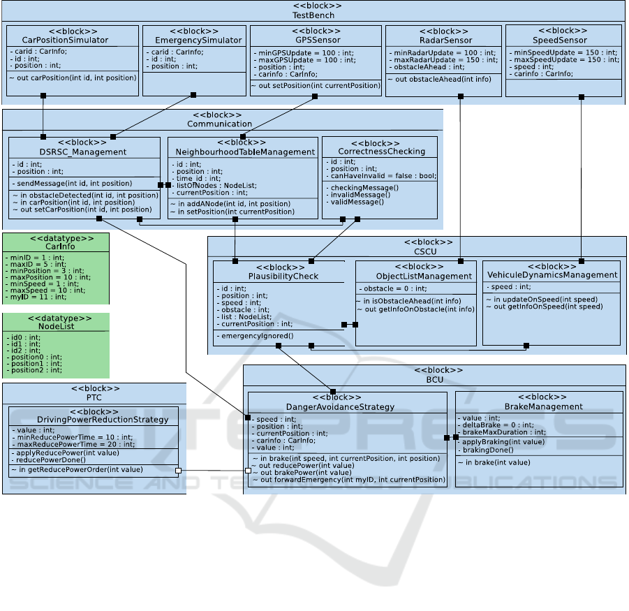
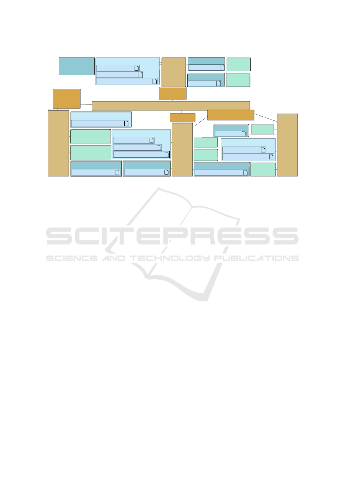
Figure 3: Active Braking Block Diagram.
Figure 2 shows the model for Partitioning: an Archi-
tecture Diagram with the tasks divided onto different
CPUs and Hardware Accelerators. Figure 3 shows the
Block Diagram for Software Design. Figure 4 shows
the Deployment Diagram. We elaborate in detail on
the different stages in the following sections.
5 HARDWARE/SOFTWARE
PARTITIONING
5.1 Modeling
The HW/SW Partitioning phase of our methodology
intends to model the abstract, high-level functional-
ity of a system (Knorreck et al., 2013). It follows
the Y-chart approach, first modeling the abstract func-
tional tasks, candidate architectures, and then finally
mapping tasks to the hardware components (Kienhuis
et al., 2002). The application is modeled as a set of
communicating tasks on the Component Design Dia-
gram (an extension of the SysML Block Instance Di-
agram). Task behavior is modeled using communi-
cation operators, computation elements, and control
elements.
The architectural modeling (Figure 2) is displayed
as a graph of execution nodes, communication nodes,
and storage nodes. Execution nodes, such as CPUs
and Hardware Accelerators, include parameters such
data size, instruction execution time, and clock ratio
(see Figure 5. CPUs also must be defined by task
switching time, cache-miss percentage, etc. Commu-
nication nodes include bridges and buses. Buses con-
nect execution and storage nodes, and bridges connect
buses. Buses are defined by parameters such as arbi-
tration policy, data size, clock ratio, etc, and bridges
are characterized by data size and clock ratio. Stor-
age nodes are Memories, which are defined by data
size and clock ratio.
Mapping involves specifying the location of tasks
on the architectural model. A task mapped onto a pro-
MODELSWARD 2017 - 5th International Conference on Model-Driven Engineering and Software Development
82
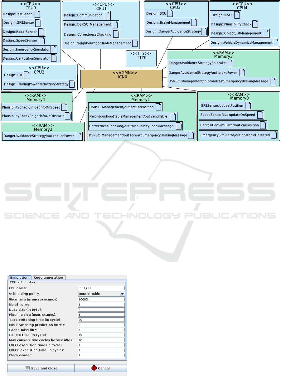
Figure 4: Deployment Diagram of the Active Braking Application: five CPUs and five RAMs.
cessor will be implemented in software, and a task
mapped onto a hardware accelerator will be imple-
mented in hardware. The exact physical path of a
data/event write may also include mapping channels
to buses and bridges. Alternatively, if the data path
is complex (e.g., DMA transfer), channels can be
mapped over communication patterns (Enrici et al.,
2014).
5.2 High-Level Simulation
Using simulation techniques described in section 3.2,
we can see that the mapping of tasks of our case study
(see Figure 2) ensures that the maximum latency be-
tween the decision (DangerAvoidanceStrategy) and
Figure 5: Adapting architecture parameters during parti-
tioning.
the resulting actions (doReduceDrivingPower and
DoBrake) respect safety requirements. Similarly, we
have verified that the worst latency between the recep-
tion of an emergency message by DRSCManagement
and the consequent actions (e.g., DoBrake) is always
also below the specified limit. These performance
verifications are performed according to the selected
functions, operating systems and hardware compo-
nents. In particular, many parameters of the hardware
components are simple values (we have for example
selected a cache-miss ratio of 5%) that are meant to
be confirmed during the software design phase.
6 SOFTWARE DESIGN WITH
AVATAR/SoCLib
Once the partitioning is complete, the AVATAR
methodology (Pedroza et al., 2011) allows the user
to design the software, perform functional simulation
and formal verification, and finally test the software
components in a virtual prototyping environment.
6.1 Software Components
Figure 3 shows the software components of the active
braking use case modeled using an AVATAR block
diagram. These modeling elements have been se-
lected during the previous modeling stage (partition-
ing). Software components are grouped according to
their destination ECU:
Model-Driven Performance Evaluation and Formal Verification for Multi-level Embedded System Design
83
• Communication ECU manages communication
with neighboring vehicles.
• Chassis Safety Controller ECU (CSCU) pro-
cesses emergency messages and sends orders to
brake to ECUs.
• Braking Controller ECU (BCU) contains two
blocks: DangerAvoidanceStrategy determines
how to efficiently and safely reduce the vehicle
speed, or brake if necessary. BrakeManager oper-
ates the brake for a given duration.
• Power Train Controller ECU (PTC) enforces
the engine torque modification request.
The AVATAR model can be functionally simu-
lated using the integrated simulator of our toolkit,
which takes into account temporal operators but com-
pletely ignores hardware, operating systems and mid-
dleware. While being simulated, the model of the
software components is animated. This simulation
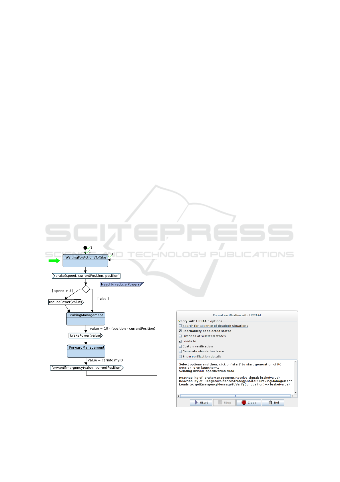
aims at identifying logical modeling bugs. Figure 6
shows the state machine of DangerAvoidanceStrat-
egy, Figure 8 shows a visualization of the generated
sequence diagram.
We show traces for the CarPositionSimulator
block and for three of the blocks which interact in an
emergency braking situation: DrivingPowerReduc-
tionStrategy, DangerAvoidanceStrategy and BrakeM-
anagement.
Figure 6: High Level Simulation of the Active Braking Au-
tomotive system: State Machine.
6.2 Formal Verification
During formal verification of safety properties with
UPPAAL, a model checker for networks of timed au-
tomata, the behavioral model of a system to be ver-
ified is first translated into a UPPAAL specification
to be checked for desired behavior. For example,
UPPAAL may verify the lack of deadlock, such as
two threads both waiting for the other to send a mes-
sage. Behavior may also be verified through “Reach-
ability”, “Leads to”, and other general statements.
The designer can indicate which states in the Ac-
tivity Diagram or State Machine Diagram should be
checked if they can be reached in any execution trace.
“Leads to” allows us to verify that one state must
always be followed by another. Other user-defined
UPPAAL queries can check if a condition is always
true, is true for at least one execution trace, or if it
will be true eventually for all execution traces. These
statements may be entered directly on the UPPAAL
model checker, or permanently stored on the model
as pragma to be verified in UPPAAL.
For example, for our case study, we can verify that
state ‘Plausibility Check’ is always executed after a
neighboring car signals that it has detected an obsta-
cle. We can also verify that an order to brake can
be received, or state ‘Braking Management’ in Task
‘Danger Avoidance Strategy’ is reachable. Figure 7
shows the UPPAAL verification window which al-
lows the user to customize which queries to execute,
and then returns the results as shown.
6.3 Prototyping
To prototype the software components with the other
elements of the destination platform (hardware com-
ponents, operating system), a user must first map
them to a model of the target system. Mapping can
Figure 7: UPPAAL Formal Verification.
MODELSWARD 2017 - 5th International Conference on Model-Driven Engineering and Software Development
84
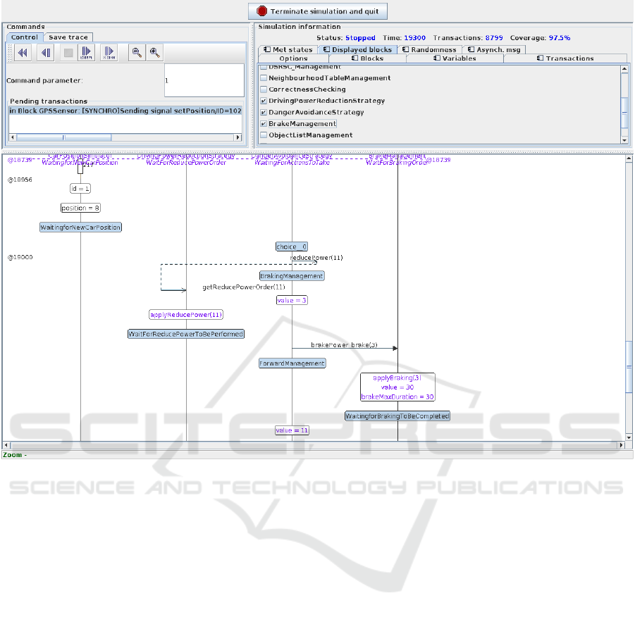
Figure 8: High Level Simulation of the Active Braking Automotive system: generated Sequence diagram.
be performed using the new deployment features re-
cently introduced in (Genius and Apvrille, 2016). An
AVATAR Deployment Diagram is used for that pur-
pose. It features a set of hardware components, their
interconnection, tasks, and channels.
The partitioning phase selected an architecture
with five clusters. Some tasks are destined to be soft-
ware tasks (they are mapped onto CPUs), and the
others are expected to be realized as hardware ac-
celerators. Yet, each specific hardware accelerator in
SoCLib needs to be developed specifically which re-
quires a significant effort. We do not consider that
case in the paper since all AVATAR tasks are soft-
ware tasks. The five clusters are represented by five
CPUs and the channels between AVATAR tasks are
implemented as software channels mapped to on-chip
RAM.
Some properties pertaining to mapping must be
explicitly captured in the Deployment Diagram, such
as CPUs, memories and their parameters, while oth-
ers, such as simulation infrastructure and interrupt
management, are added transparently to the top cell
during the transformation to SoCLib. Figure 4 shows
the Deployment Diagram of the software components
of the active braking application mapped on five pro-
cessors and five memory elements. From the Deploy-
ment Diagram, a SoCLib prototype is then generated.
This prototype consists of a SystemC top cell, the em-
bedded software in the form of POSIX threads com-
piled for the target processors, and the embedded op-
erating system (Figure 9).
6.4 Capturing Performance
Information
We now present how performance information can be
obtained from the use case simulated with SoCLib. In
the experiments shown here, we use PowerPC cores.
The cycle accurate bit accurate (CABA)-level simu-
lation allows measurement of cache miss rates, la-
tency of any transaction on the interconnect, tak-
ing/releasing of locks, etc. Since SoCLib hardware
models are much more precise than the ones used
at the design space exploration level, precise timing
and hardware mechanisms can be evaluated. How-
ever, these evaluations take considerable time com-
pared to high-level simulation/evaluation. We restrict
Model-Driven Performance Evaluation and Formal Verification for Multi-level Embedded System Design
85
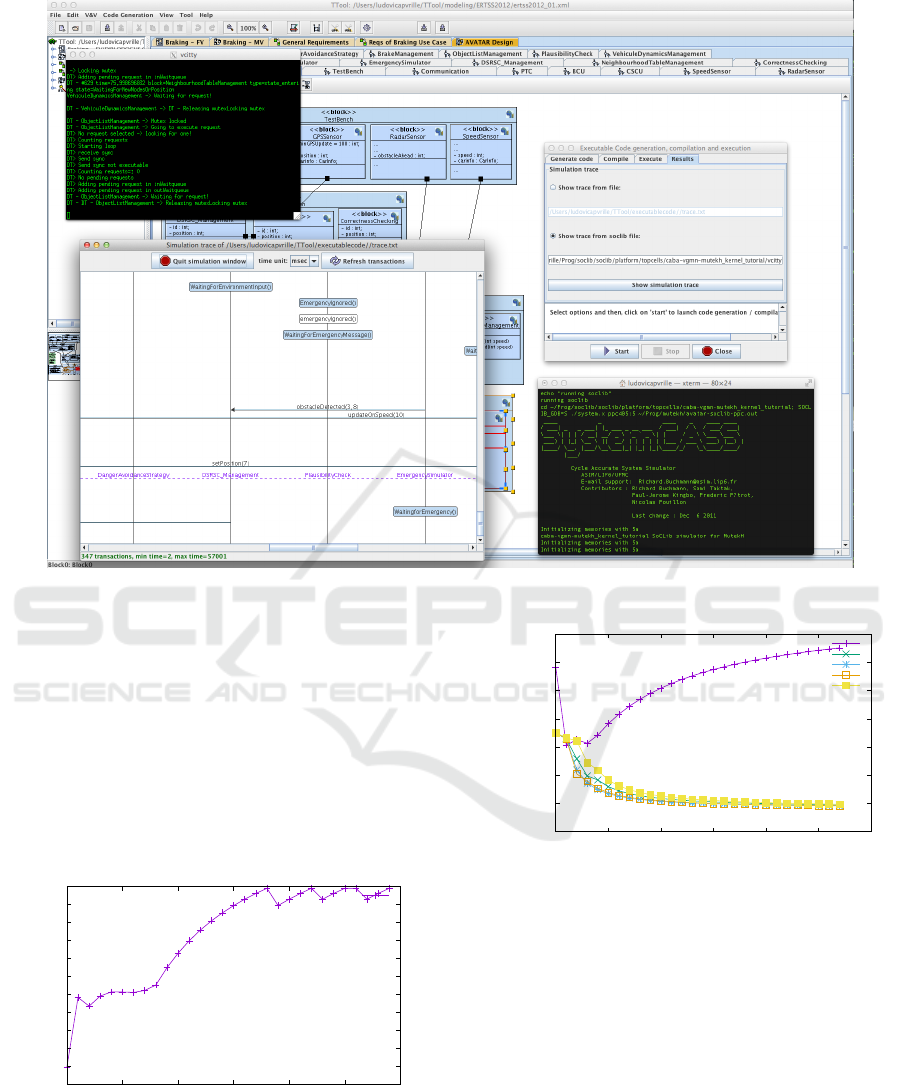
Figure 9: AVATAR/SoCLib Prototyping Environment in TTool.
ourselves to using only the hardware counters avail-
able in the SoCLib cache module.
We start by an overview of performance problems.
For this, we use an overall metric summing up all phe-
nomena that slow down execution of instructions by
the processor, such as memory access latency, inter-
connect contention, overhead due to context switch-
ing etc.: Cycles per Instruction (CPI). For bottom line
comparison, the CPI is first measured on a mono pro-
cessor platform (Figure 10). On this platform, the sin-
gle processor is constantly overloaded (CPI > 16).
14
14.2
14.4
14.6
14.8
15
15.2
15.4
15.6
15.8
16
16.2
0 5 10 15 20 25 30
CPI
mio. simulation cycles
cpu
Figure 10: CPI per processor for a mono processor config-
uration.
Our tool allows per-processor performance evalu-
ation, which is particularly useful in detecting unbal-
anced CPU loads. Even when prototyping onto five
2
4
6
8
10
12
14
16
0 5 10 15 20 25 30
CPI
mio. simulation cycles
cpu0
cpu1
cpu2
cpu3
cpu4
Figure 11: CPI per processor for a 5 processor configura-
tion.
processors (Figure 11) to reflect the DIPLODOCUS
partitioning, the CPU loads are not very well bal-
anced. This is due to the fact that currently, a cen-
tral request manager is required to capture the se-
mantics of AVATAR channels. Requests are stored
in waiting queues for synchronous as well as asyn-
chronous communication, and, in synchronous com-
munications, cancelled when they became obsolete.
CPU0 frequently needs to access memory areas stor-
ing the boot sequence and the central request man-
ager. Future work will address a better distribution of
these functionalities, called the AVATAR runtime, over
the MPSoC architecture. Another interesting observa-
tion is that in the five processor configuration, CPU4
MODELSWARD 2017 - 5th International Conference on Model-Driven Engineering and Software Development
86
is more strongly challenged than the others. Look-
ing at the AVATAR block diagram, it becomes clear
that the CSCU, mapped on CPU4, is connected by
AVATAR channels to all the other ECUs.
We now investigate the cache miss rate. One
important parameter of the CPU used in the
DIPLODOCUS partitioning is the overall cache miss
rate (see line Cache-miss in Figure 5). While the es-
timated 5% of cache misses includes both data and
instruction cache misses, SoCLib measures them sep-
arately. Instruction cache miss rates will be higher for
the cache of CPU0 because the central request man-
ager runs on this CPU, as noted in the previous para-
graph.
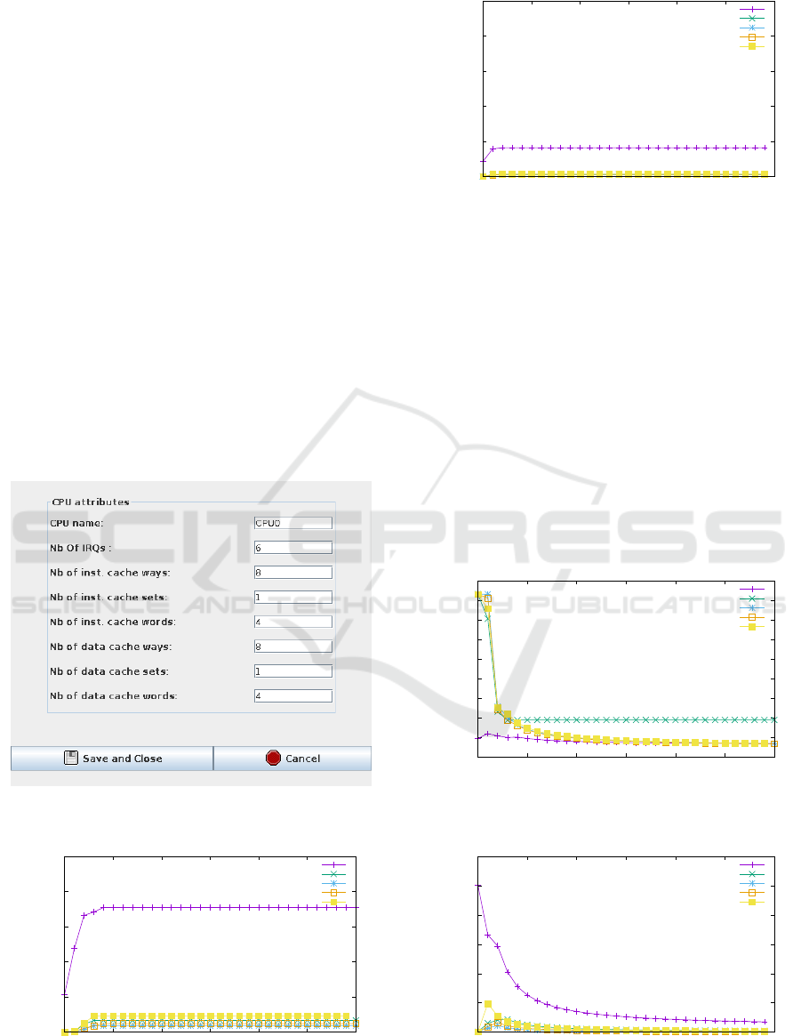
We vary size and associativity of both caches, ini-
tially considering direct mapped caches (Figure 13),
then setting associativity to four (Figure 14) for the
same size. This action can be performed with a few
mouse clicks (see Figure 12). For the instruction
cache, using the same parameters (Figures 15 and 16),
miss rates are closer to the estimated ones.
Even if we do not explore the cache parameters
fully in the work presented here, we can already con-
Figure 12: Varying cache associativity with a few mouse
clicks.
0
2x10
-7
4x10
-7
6x10
-7
8x10
-7
1x10
-6
0 5 10 15 20 25 30
Cache miss rate
mio. simulation cycles
cpu 0
cpu1
cpu2
cpu3
cpu4
Figure 13: Data cache misses per processor for a 5 proces-
sor configuration with a direct mapped cache.
0
2x10
-7
4x10
-7
6x10
-7
8x10
-7
1x10
-6
0 5 10 15 20 25 30
Cache miss rate
mio. simulation cycles
cpu 0
cpu1
cpu2
cpu3
cpu4
Figure 14: Data cache misses per processor for a 5 proces-
sor configuration with 4 cache sets.
clude from this first exploration that data cache misses
were overestimated; they are below 10
−7
. As for in-
struction cache misses, they are below 10% for the
cache of CPU0, below 2% for the other four caches.
We can thus lower the estimations, distinguishing
between CPU0 and the others. Since our toolkit does
not distinguish between data and instruction cache
misses during partitioning, we take the less favorable
case of instruction cache misses and raise the miss
rate for CPU0 to 10%, and lower it to 2% for the oth-
ers. Figure 5 shows the window for customizing the
CPU during partitioning, where we can now adapt the
cache miss rate (and redo the partitioning).
We finally compare the influence of the intercon-
0.25
0.3
0.35
0.4
0.45
0.5
0.55
0.6
0.65
0.7
0 5 10 15 20 25 30
Cache miss rate
mio. simulation cycles
cpu 0
cpu1
cpu2
cpu3
cpu4
Figure 15: Instruction cache misses per processor for a 5
processor configuration with a direct mapped cache.
0
0.02
0.04
0.06
0.08
0.1
0.12
0 5 10 15 20 25 30
Cache miss rate
mio. simulation cycles
cpu 0
cpu1
cpu2
cpu3
cpu4
Figure 16: Instruction cache misses per processor for a 5
processor configuration with 4 cache sets.
Model-Driven Performance Evaluation and Formal Verification for Multi-level Embedded System Design
87
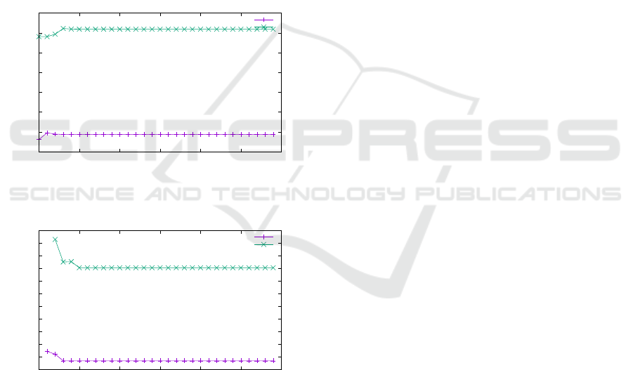
nect latency (10 and 20 cycles, see Figures 17 and
18). We observe a significant influence on the cost of
a cache miss; latency of data cache misses is generally
higher.
We observe after these first exploration steps that
apart from correcting the estimated cache miss rate
in DIPLODOCUS, adding another CPU in order to
take some of the load from CPU4 would improve the
performance.
As we can see in the CPU attributes window of
Figure 5, our toolkit potentially allows a designer to
improve estimates of several more hardware parame-
ters like branch misprediction rate and go idle time.
Until now, we used only the hardware counters im-
plemented in the SoCLib components. Taking into
account the OS, over which we have full control, we
will soon be able to address other issues such as task
switching time.
30
35
40
45
50
55
60
65
0 5 10 15 20 25 30
cycles
mio. simulation cycles
latency 10
latency 20
Figure 17: Cost of instruction cache miss in cycles for a 5
processor configuration with 4 cache sets.
40
45
50
55
60
65
70
75
80
85
90
95
0 5 10 15 20 25 30
cycles
mio. simulation cycles
latency 10
latency 20
Figure 18: Cost of data cache miss in cycles for a 5 proces-
sor configuration with 4 cache sets.
7 DISCUSSION AND FUTURE
WORK
Our model-driven approach with a SysML-based
methodology and supporting toolkit enables design-
ers to capture systems at multiple levels and facili-
tates the transitions between embedded system design
stages. Prototyping from AVATAR enables the user to
take into account performance results in a few clicks
in the Deployment Diagram, though the process is not
yet fully automated.
In order to deliver more realistic results, we
are currently working on integrating clustered archi-
tectures. These architectures are supported in So-
Clib, but various details make top cell generation
much more complex (two-level mapping table, ad-
dress computation complexity, etc.).
To help backtrace low level results (prototyping)
to a higher level (partitioning), we are currently work-
ing on providing the performance graphs shown in the
paper directly and automatically in the toolkit. Also,
most metrics we have exemplified are CABA-based.
We could also propose two other abstraction levels
of SoCLib: TLM (Transaction Level) and TLM-T
(Transaction Level with Time). Future work will fo-
cus on adding these intermediate levels, considerably
speeding up prototypes at the cost of loss of preci-
sion to be evaluated. However, using this intermediate
level of abstraction would smooth the development
gap between system-level and low-level prototyping.
REFERENCES
Apvrille, L. (2015). Webpage of TTool. In http://ttool.
telecom-paristech.fr/.
Balarin, F., Watanabe, Y., Hsieh, H., Lavagno, L.,
Passerone, C., and Sangiovanni-Vincentelli, A. L.
(2003). Metropolis: An integrated electronic system
design environment. IEEE Computer, 36(4):45–52.
Basu, A., Bensalem, S., Bozga, M., Combaz, J., Jaber,
M., Nguyen, T.-H., and Sifakis, J. (2011). Rigorous
component-based system design using the BIP frame-
work.
Becoulet, A. (2009). Mutekh operating system (webpage).
http://www.mutekh.org.
Bengtsson, J. and Yi., W. (2004). Timed automata: Seman-
tics, algorithms and tools. In Lecture Notes on Con-
currency and Petri Nets, pages 87–124. W. Reisig and
G. Rozenberg (eds.), LNCS 3098, Springer-Verlag.
Blanchet, B. (2010). Proverif automatic cryptographic
protocol verifier user manual. Technical report,
CNRS, D
´
epartement d’Informatique
´
Ecole Normale
Sup
´
erieure, Paris.
Buck, J., Ha, S., Lee, E. A., and Messerschmitt, D. G.
(2002). Ptolemy: a framework for simulating and pro-
totyping heterogeneous systems. Readings in hard-
ware/software co-design, pages 527–543.
Enrici, A., Apvrille, L., and Pacalet, R. (2014). A uml
model-driven approach to efficiently allocate complex
communication schemes. In MODELS conference,
Valencia, Spain.
Erbas, C., Cerav-Erbas, S., and Pimentel, A. D. (2006).
Multiobjective optimization and evolutionary algo-
MODELSWARD 2017 - 5th International Conference on Model-Driven Engineering and Software Development
88

rithms for the application mapping problem in multi-
processor system-on-chip design. IEEE Transactions
on Evolutionary Computation, 10(3):358–374.
EVITA (2011). E-safety Vehicle InTrusion protected Ap-
plications. http://www.evita-project.org/.
Feiler, P. H., Lewis, B. A., Vestal, S., and Colbert, E.
(2004). An overview of the SAE architecture anal-
ysis & design language (AADL) standard: A basis
for model-based architecture-driven embedded sys-
tems engineering. In Dissaux, P., Filali-Amine, M.,
Michel, P., and Vernadat, F., editors, IFIP-WADL, vol-
ume 176 of IFIP, pages 3–15. Springer.
Gamati
´
e, A., Beux, S. L., Piel,
´
E., Atitallah, R. B., Etien,
A., Marquet, P., and Dekeyser, J.-L. (2011). A model-
driven design framework for massively parallel em-
bedded systems. ACM Trans. Embedded Comput.
Syst, 10(4):39.
Genius, D. and Apvrille, L. (2016). Virtual yet precise pro-
totyping : An automotive case study. In ERTSS’2016,
Toulouse.
Genius, D., Faure, E., and Pouillon, N. (2011). Mapping
a telecommunication application on a multiprocessor
system-on-chip. In Gogniat, G., Milojevic, D., and
Erdogan, A. M. A. A., editors, Algorithm-Architecture
Matching for Signal and Image Processing, chapter 1,
pages 53–77. Springer LNEE vol. 73.
Kahn, G. (1974). The semantics of a simple language for
parallel programming. In Rosenfeld, J. L., editor, In-
formation Processing ’74: Proceedings of the IFIP
Congress, pages 471–475. North-Holland, New York,
NY.
Kelling, E., Friedewald, M., Leimbach, T., Menzel, M.,
Sieger, P., Seudi
´
e, H., and Weyl, B. (2009). Specifi-
cation and evaluation of e-security relevant use cases.
Technical Report Deliverable D2.1, EVITA Project.
Kienhuis, B., Deprettere, E., van der Wolf, P., and Vissers,
K. (2002). A Methodology to Design Programmable
Embedded Systems: The Y-Chart Approach. In Em-
bedded Processor Design Challenges, pages 18–37.
Springer.
Knorreck, D., Apvrille, L., and Pacalet, R. (2013). For-
mal System-level Design Space Exploration. Con-
currency and Computation: Practice and Experience,
25(2):250–264.
Li, L., Apvrille, L., and Genius, D. (2016). Virtual pro-
totyping of automotive systems: Towards multi-level
design space exploration. In Conference on Design
and Architectures for Signal and Image Processing.
Pedroza, G., Knorreck, D., and Apvrille, L. (2011).
AVATAR: A SysML environment for the formal veri-
fication of safety and security properties. In The 11th
IEEE Conference on Distributed Systems and New
Technologies (NOTERE’2011), Paris, France.
Pimentel, A. D., Hertzberger, L. O., Lieverse, P., van der
Wolf, P., and Deprettere, E. F. (2001). Exploring
embedded-systems architectures with artemis. IEEE
Computer, 34(11):57–63.
Polarsys (2008). ARCADIA/CAPELLA (webpage).
SoCLib consortium (2010). SoCLib: an open platform for
virtual prototyping of multi-processors system on chip
(webpage). In http://www.soclib.fr.
Sodius Corporation (2016). MDGen for SystemC. http://
sodius.com/products-overview/systemc.
Syed-Alwi, S.-H., Braunstein, C., and Encrenaz, E. (2013).
Efficient Refinement Strategy Exploiti ng Component
Properties in a CEGAR Process, volume 265 of Lec-
ture Notes in Electrical Engineerin g, chapter 2, pages
17–36. Springer.
Vidal, J., de Lamotte, F., Gogniat, G., Soulard, P., and
Diguet, J.-P. (2009). A co-design approach for embed-
ded system modeling and code generation with UML
and MARTE. In DATE’09, pages 226–231.
VSI Alliance (2000). Virtual Component Interface Standard
(OCB 2 2.0). Technical report, VSI Alliance.
Yu, H., Joshi, P., Talpin, J.-P., Shukla, S. K., and Shiraishi,
S. (2015). The challenge of interoperability: model-
based integration for automotive control software. In
DAC, pages 58:1–58:6. ACM.
Model-Driven Performance Evaluation and Formal Verification for Multi-level Embedded System Design
89
