
Using Constraint Solver for 3D Layout Assistance in Human-scale
Virtual Environment
Marouene Kefi
1
, Paul Richard
1
, Thuong Hoang
2
, Takehiko Yamaguchi
3
and Vincent Barichard
4
1
Laboratoire Angevin de Recherche en Ing
´
enierie des Syst
`
emes (LARIS - EA 7315), University of Angers, Angers, France
2
Microsoft Research Centre for Social Natural User Interfaces, University of Melbourne, Victoria, Australia
3
Faculty of Industrial Science and Technology, Tokyo University of Sciences, Tokyo, Japan
4
Laboratoire d’Etude et de Recherche en Informatique d’Angers (LERIA - EA 2645), University of Angers, Angers, France
Keywords:
Virtual Reality, Human-scale Interaction, Constraint Programming, 3D-Spatial Configuration, Human
Performance.
Abstract:
This paper proposes a combination of virtual reality (VR) and constraint programming (CP) to develop an
efficient system that will assist users when performing 3D layout tasks in a virtual environment. We conducted
an experimental study to investigate the extent to which the solver’s assistance affects user performance in 3D-
layout tasks. Volunteer participants were instructed to layout a generic 3D scene which was displayed on a
large-scale rear-projected screen. Results showed that the solver provided significant assistance in both simple
and complex tasks. The participants performed the layout tasks more accurately and in significantly less time
when the constraint solver was used. Most of the subjects reported that the solver was useful in completing the
layout tasks and they were generally satisfied by the proposed solution. However, it was observed that some
subjects had difficulty in interacting with the solver, especially during the complex tasks.
1 INTRODUCTION
Solving three-dimensional (3D) placement or layout
problems consists of placing components (i.e., a set
of 3D objects) inside of a virtual container while sat-
isfying a set of given constraints. These constraints
allow to specify how components, such as furniture
and equipment, may be combined together to make a
single layout. In such problems, the components and
the container are generally functionally and geometri-
cally linked. Depending on the designer’s experience
level, the development of semi-automatic methods for
the resolution of spatial problems is often an inter-
esting challenge as systems become more and more
complex. This challenge relies on the difficulty of
modeling and formulating these problems, as well as
the difficulty of identifying resolution strategies.
Constraints are naturally present in several areas
such as resources allocation, planning and industrial
productions. A constraint expresses a property or con-
dition that should be satisfied and is generally defined
as a relationship between variables (positions of ob-
jects in our case). The spatial problems can be mod-
eled using an efficient framework such as the Con-
straint Satisfaction Problem (CSP) formalism. Solv-
ing a CSP consists of assigning values to the variables
while satisfying all the constraints (Fruhwirth and Ab-
dennadher, 2003). Algorithms used to solve a CSP are
called constraints solvers.
In recent years, VEs have become increasingly
popular due to advances in graphics technology and
user interfaces (Messinger et al., 2009). VEs are rec-
ognized as powerful design tools in most industrial
sectors such as manufacturing, process engineering,
and aerospace (Zorriassatine et al., 2003). One of the
possible uses of VEs can be to monitor decision mak-
ing process such as the 3D-object layout problems (or
spatial problems) involving constraints-based com-
plex tasks. However, in many cases, VEs are only
being used as pure visualization tools for assessing
final designs (Drieux et al., 2005) and do not gener-
ally provide assistance to the user and more specif-
ically in 3D-layout tasks where an accurate place-
ment of objects is required (Essabbah et al., 2014).
Thusly, the integration of intelligent modules such as
constraints solvers could make VEs more efficient to
solve spatial configuration problems (Sanchez et al.,
2002; Calderon et al., 2003). In this context, specific
interaction techniques and assistance involving both
3D objects and constraint solvers need to be devel-
Kefi M., Richard P., Hoang T., Yamaguchi T. and Barichard V.
Using Constraint Solver for 3D Layout Assistance in Human-scale Virtual Environment.
DOI: 10.5220/0006140400270038
In Proceedings of the 12th International Joint Conference on Computer Vision, Imaging and Computer Graphics Theory and Applications (VISIGRAPP 2017), pages 27-38
ISBN: 978-989-758-229-5
Copyright
c
2017 by SCITEPRESS – Science and Technology Publications, Lda. All rights reserved
27

oped and evaluated. In other words, our objective is
to facilitate the interaction between the user and the
solver to efficiently layout a 3D scene.
This paper is organized as follows. In Section 2,
we provide an overview of relevant research works
and discusses our system. The interaction model
and communication process between the VE and the
solver is then detailed in Section 3. An experimental
study with description of research methodologies and
measurements is described in Section 4. The results
are presented in Section 5 with discussion in Section
6. Section 7 concludes the study with recommenda-
tions for future work.
2 RELATED WORK
Previous works have shown the relevance of CP tech-
niques in spatial configuration problems. Fernando
et al. provided the design and implementation details
of a constraint-based VE (Fernando et al., 1999), pre-
senting a software framework to support constraint-
based assembly and maintenance operations. Xu
et al. studied the combination of physics, seman-
tics, and placement constraints to investigate how
such combination permits a user to quickly and eas-
ily layout a scene (Xu et al., 2002). The 3D-layout
was substantially accelerated with a simple pseudo-
physics engine and a small amount of semantic in-
formation. They generalized this approach and de-
veloped a richer set of semantic information leading
to a new modeling technique. Sanchez et al. pre-
sented a general-purpose constraint-based system for
non-isothetic 3D-object layouts, built on a genetic al-
gorithm (Sanchez et al., 2002). This system is able
to process a complex set of constraints, including ge-
ometric and pseudo-physics designs. To create an
easy-to-use object-layout software, Sanchez and his
colleagues described the 3D-scene by using seman-
tic and functional features associated with the objects
in regards to the layout. Smelik et al. used semantic
constraint, a control mechanism imposed on the pro-
cedural generation of VEs, in order to satisfy explicit
designers intent over a specific area. It is composed
of sub-constraints feature mapped to low-level opera-
tions (Smelik et al., 2011).
Several approaches approximate the relation-
ships between a large number of components
with simplified ”dimensional constraints” aiming at
formulating the design problem as a system of
(in)equalities. In this context, Theodosiou et al.
proposed informational-complete models for design-
constraints based on the analysis of geometric and
non-geometric properties of the related space vol-
umes (Theodosiou and Sapidis, 2004). An extended
product model was proposed describing the system’s
structure and components as well as related proce-
dures and constraints to be used as a system life-cycle
model. Sutherland proposed a communication system
called ”Sketchpad” that uses geometric constraints to
allow a user and a computer converse rapidly with
line drawings (Sutherland, 1964). On the other hand,
Marriott et al. proposed a generic algorithm for lin-
ear arithmetic constraints that makes use of the Cas-
sowary constraint solving algorithm (Marriott et al.,
2001). Marriott and her colleagues described an algo-
rithm for rapidly resolving disjunctions of constraints.
The algorithm is designed to support direct manipula-
tion in interactive graphical applications which con-
tain non-overlap constraints between graphical ob-
jects. They also demonstrated that the solver can sup-
port non-overlap of complex non-convex polygons,
and complex diagrams such as State Charts that con-
tain non-overlap as well as containment constraints.
Calderon et al. presented a novel framework for the
use of VEs in interactive problem solving (Calderon
et al., 2003). This framework extends visualization
to serve as a natural interface for the exploration of
configurations space, and enables the implementation
of reactive VEs. Their implementation was based
on a fully-interactive solution where both visualiza-
tion and the generation of a new solution are under
the user control. To visualize and control logic pro-
grams, Fages et al. developed a generic graphic user-
interface (CLPGUI). The proposed architecture in-
volves a CLP process and a Graphical User Interface
(GUI) which communicate through sockets (Fages
et al., 2004). This approach has been evaluated us-
ing a simple layout problem involving a basic layout
scene. Jacquenot developed a hybrid generic method
to solve multi-objective placement problems for free
form components (Jacquenot, 2009). The proposed
method is a hybrid algorithm based on both a genetic
and separation algorithms. Tim et al. introduced a
novel rule-based layout solving approach to speed-up
manual design methods and create parts of a game
world automatically (Tim et al., 2009). They showed
that their solving approach may be used for proce-
dural generation by providing the solver with a user
defined plan. In this plan, users can specify objects to
be placed as instances of classes, which in turn con-
tain rules about how instances should be placed. They
validated their approach in different procedural gen-
eration scenarios. Medjdoub presented a system for
ceiling-mounted fan coil system in a building ceiling.
The system is simple to use with interactive modifica-
tion of the 3D parametric model (Medjdoub, 2004).
He showed that this approach significantly reduced
HUCAPP 2017 - International Conference on Human Computer Interaction Theory and Applications
28

design costs, improved the quality of the solution,
and produced additional benefits in the supply chain.
More recently, Merrell et al. identified a set of inte-
rior design guidelines for furniture layout and devel-
oped an interactive system that suggests possible fur-
niture arrangements based on these guidelines. The
system incorporates the layout guidelines as terms in
a density function and generates layout suggestions
by rapidly sampling the density function using a hard-
ware accelerated Monte Carlo sampler (Merrell et al.,
2011). The user is able to interact with the system to
iteratively evolve the design of the interior.
Although interesting, most of the studies de-
scribed above have some limitations and can be ex-
tended in several directions. One way to extend the
research is to offer a deeper integration of the user to
increase the interaction with the solver. For instance,
during a 3D layout, the user should be able to: (1) add
and manipulate objects from a menu at any time in the
environment and (2) manually place some objects in
the environment, the placement of the other objects
being automatic.
3 SYSTEM DESCRIPTION
Before describing the architecture and the interaction
model of the proposed system, we first present the
solver process used to find a solution of a modeled
problem using a CSP formalism.
3.1 3D Layout Problem Formulation
To model a 3D layout problem, a CSP formalism was
chosen, which offers a simple way to model and solve
such problems. A set of variables (i.e., unknowns
of the problem) and constraints have been identified.
Each of these variables takes its values from a given
domain. As such, the resolution of a CSP consists of
assigning a value to each variable from its domain in
order to satisfy all the constraints. The basic resolu-
tion process involves two stages: (1) constraint prop-
agation and (2) enumerations (Fruhwirth and Abden-
nadher, 2003).
1. Constraint Propagation: Constraint propagation
consists of reducing variables domains by re-
moving values to eliminate portions of the search
space that cannot be part of a solution.
bool Propagate(C,Vc,D){
f or all var in Vc{
f or all value in D(var){
f ind a solution to C with var = value
i f no solution exists, remove value f rom D(var)
i f D(var) is empty return f alse
}
}
return true }
2. Enumeration Steps: Enumeration involves a suc-
cession of decisions (to approach a solution) con-
sisting of choosing a value for each variable from
the remaining domain.
A 3D layout problem can be modeled through the
following parameters:
• Container: the space to be laid out
• Objects: objects to be placed in the container such
as furniture or materials.
• Layout Requirements: constraints or restrictions
linking objects between them and the container.
To formulate the problem, it was supposed that
the VE of dimensions (w,h,d), is composed of n ob-
jects related by m constraints. Let X be the set of the
unknowns of the problem (3D positions of objects),
D be a function that associates a domain (authorized
values) to each variable, and C be the set of layout
constraints. Thus, the problem can be defined by the
triplet (X,D ,C):
• X = {x
1
,y
1
,z
1
,...,x
n
,y
n
,z
n
}, (x
i
,y
i
,z
i
/i ∈ [1, n]) is
the position center of ob ject
i
• D(x
i
) = [w
i
,w − w
i
], w
i
/i ∈ [1,n] is the width of
ob ject
i
D(y
i
) = [h
i
,h − h
i
], h
i
/i∈ [1,n] is the height of
ob ject
i
D(z
i
) = [d
i
,d − d
i
], d
i
/i∈ [1,n] is the depth of
ob ject
i
• C = {c
i, j
1
,c
i, j
2
,...,c
i, j
m
}, c
i, j
k
/(k ∈ [1, m] and i, j ∈
[1,n]) is a constraint between ob ject
i
and ob ject
j
.
3.2 Proposed System
The proposed system is based on a human-scale, real-
time VE which supports the resolution of interactive
3D-object layouts using ongoing communication with
an efficient constraint-solver (Gecode) written in C++
language. The selection of objects and constraints as
well as a user’s 3D manipulation is converted into
queries sent to the solver. The solver’s outputs (po-
sitions of objects) allow real-time automatic reconfig-
uration of the 3D scene.
Figure 1 illustrates the general resolution process
and the link between the 3D environment and the
Using Constraint Solver for 3D Layout Assistance in Human-scale Virtual Environment
29
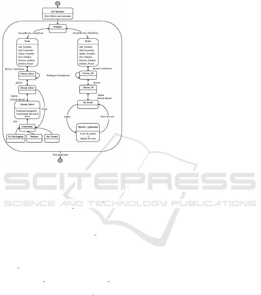
Figure 1: System architecture (event exchange between VE
and Solver).
solver. The events exchange is managed by a Man-
ager class which creates and sends the corresponding
event to the visualization module (Process 3D) and
the resolution module (Process Solver). Each module
sends the requests to the appropriate thread. To ensure
real-time interaction, each module runs on a differ-
ent thread. The request sent to the Thread 3D is to
display the selected objects. The Thread Solver class
creates a CSP in which the variables are the positions
of the center of selected objects, and the constraints
are those initially specified. The Gecode solver is
called to find a solution to the proposed problem. The
Thread Solver class will be informed about the results
and will transmit the corresponding request to the up-
per level (Process Solver). Thus the Process Solver
class informs the Manager class that a solution has
been found (through the event ”Solution found”). The
resulting 3D positions of each object are then for-
warded level by level until the VE reconfigures itself
by updating the 3D scene.
3.3 Interaction Framework
In the proposed system, user manipulations inside the
VE can be summarized in the following actions or
groups of actions: (1) add/remove/displace objects,
(2) add/remove constraints, and (3) call the solver to
search a solution for a defined layout problem. A
Nintendo Wiimote
TM
was used as an input device for
(de)selecting and moving objects in the 3D space. To
track the user’s hand position, the Wiimote
TM
was
equipped with two retroreflective markers, tracked by
an OptiTrack
TM
motion capture system (OptiTrack,
2011). A Nunchuk
TM
was used to interact with the
solver and to select constraints from a menu. Wiimote
devices offer multiple interaction methods, such as
buttons, vibro-tactile feedback, that can be easily in-
tegrated in any VR systems at a relatively low price.
To add objects in the VE, the user selects and in-
troduces a given object (e.g., cube, sphere or cone)
using the 3D menu. To do this, he/she must press and
hold the B button on the Wiimote
TM
and gesture to
move a given object to a desired position. The se-
lected object is released when the user releases the B
button. With the same way, the user can apply con-
straints on the selected objects. After selecting one or
several objects, the Nunchuk
TM
is used to view (using
the joystick) and select (Z button) a desired constraint
from a constraint menu and trigger the solver. To fa-
cilitate constraint identification, a description (i.e., in-
formation sheets) of each one is displayed on the top
of the screen as 2D text.
It is also important to make note of how the solver
responds to the user’s requests and how the solver’s
results are interpreted in the VE. The main goal of
the interaction model is to make the link between
the user’s interactions and the inputs/outputs of the
solver. In other words, the interaction model was
developed to facilitate user interaction since model-
ing the problem and finding solutions are completely
transparent for the user. The user’s manipulation,
such as the selection of objects and constraints as well
as objects transformations (rotation and translation),
are converted to queries sent to the solver. Based
on these queries, the solver updates the existing CSP
or creates a new one if new objects are added to the
scene. Next, the solver instructs the updated or the
newly-created CSP to find a new solution. Consider
the example in which the user defines a layout prob-
lem by adding some objects in the VE and selecting
a set of constraints. According to the user’s choices,
the system will automatically create a CSP that repre-
sents the problem. The formulation and the resolution
of this problem is left to the solver and this process is
completely transparent to the user (Fig. 2).
Algorithms for solving constraint-based problems
are generally triggered by changing the values of vari-
ables and/or constraints which define the problem.
In our case, user interaction will be translated into
changes in relevant variables. For instance, if the user
displaces a given object, the associated constraints are
HUCAPP 2017 - International Conference on Human Computer Interaction Theory and Applications
30
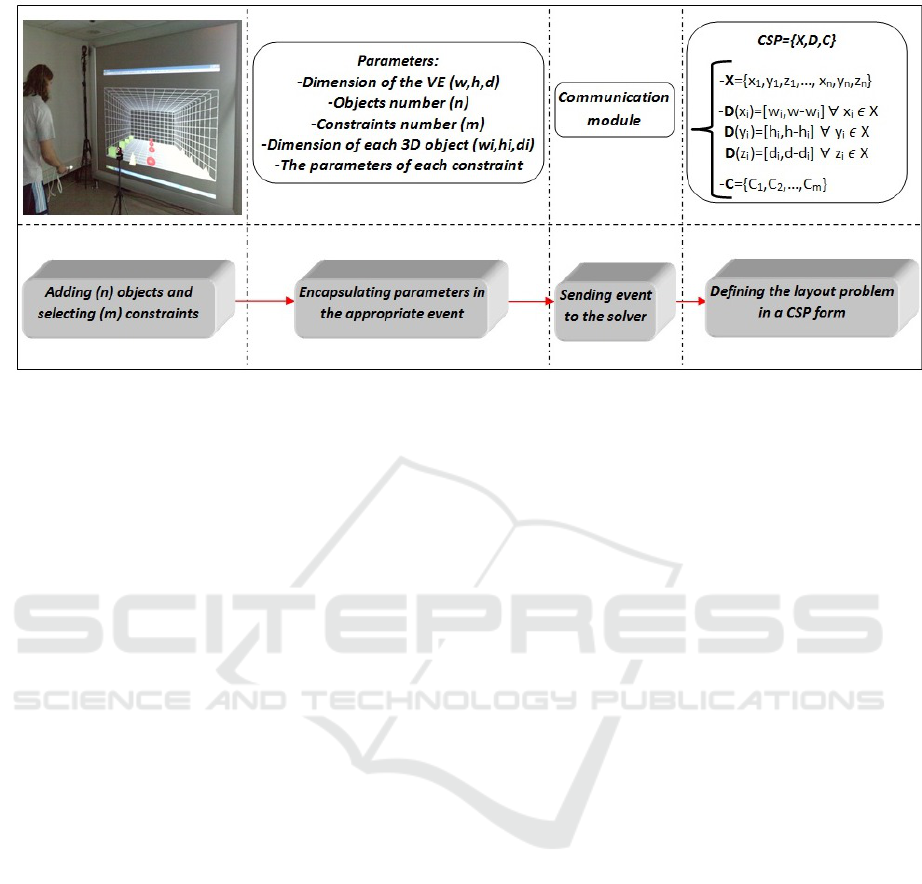
Figure 2: Architecture of the system.
modified. This displacement triggers the solver which
propagates the constraints and computes new results.
Let us consider a simple example where the user
moves the gray object (circled object) to the right
(Fig.3). An event will be automatically generated and
a new constraint, which sets the position of the gray
object, is defined in the already created CSP. These
constraints will be applied on the object whose in-
dex is encapsulated in the event sent to the solver.
Therefore the solver is re-called to detect a possible
constraints dissatisfaction and to compute the objects’
positions while respect all the constraints. The com-
puted data are encapsulated in another event sent to
the VE via the communication module, in order to re-
configure the 3D scene.
4 EXPERIMENTAL STUDY
Previous studies did not provide detailed analysis
of the human performance, and particularly, nor the
comparison between manual (without solver) and as-
sisted (with solver) 3D-layout tasks. There are multi-
ple issues to be considered when integrating a con-
straint solver in a VE: data exchange between the
constraint solver and VE, user interaction, and effec-
tive and sufficient user assistance. An experimental
study was conducted to evaluate the effectiveness of
a combination of a solver and a VE, with special fo-
cus on the interaction technique. Various data were
collected, including the effects on task completion
time and placement accuracy, as well as subjective
preference from users. The study compared two ap-
proaches, namely manual and assisted, with two dif-
ferent levels of layout difficulty, simple and complex.
The following hypotheses were proposed:
1. H1: the participants are satisfied with the solver
assistance.
2. H2: the interaction with the solver during the lay-
out task is easy.
3. H3: the participants solve the layout task faster
with the solver.
4. H4: the participants make fewer placement errors
with the solver.
A NASA-TLX questionnaire was used to access
user’s satisfaction (H1) and the ease of interaction
with the solver (H2). Task completion data was
collected for H3. The satisfaction of the hypothesis
H4 is relatively obvious since a solver does not make
errors. However, it is important to confirm it in the
interest of the solver integration.
4.1 Experimental Design
Twenty two subjects were recruited from a local
university aged from 22 to 47. The participants were
asked about their previous experience with video
games and VR and to rate their level of expertise.
For prior video games experience, fifteen out of the
twenty two participants answered yes to this question.
For VR expertise, seven subjects claimed they had a
moderate amount of experience with VR tasks while
nine subjects rated their experience as low and eight
as high.
A 2 x 2 balanced, within-subjects factorial design,
was used where the independent variables were the
user assistance (UA) and the task complexity level
(TCL). The first factor (UA) has two levels: assisted
Using Constraint Solver for 3D Layout Assistance in Human-scale Virtual Environment
31
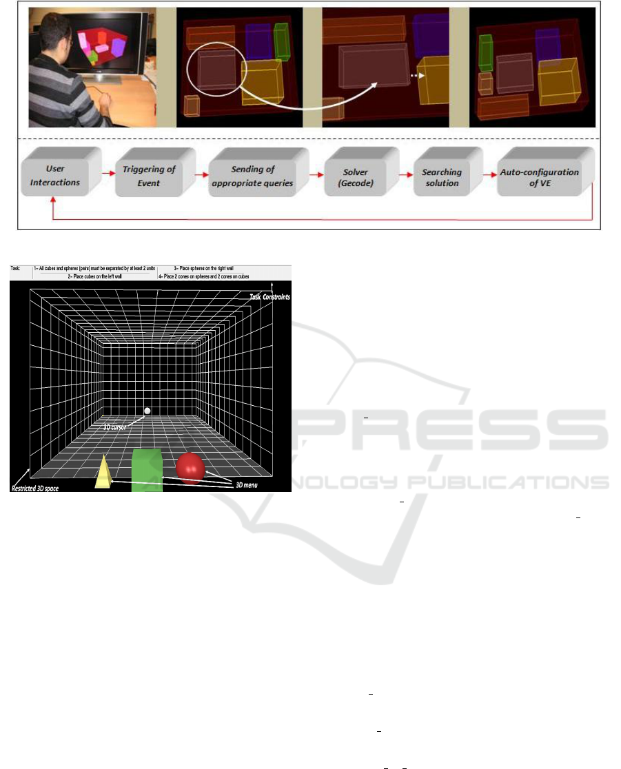
Figure 3: Illustration of the rearrangement of the 3D scene according to an object displacing.
Figure 4: Snapshot of the virtual environment at the begin-
ning of the task.
(with solver) and manual (without solver). Through a
rear-projected human-scale VE (Richard et al., 2006),
participants were instructed to layout twelve 3D ob-
jects (four cubes, four spheres and four cones) in the
space represented as a large 3D room while respecting
the constraints described with on-screen text. In order
to be able to generalize the results to different appli-
cation contexts a generic task and simple 3D environ-
ment was chosen. The task involves some constraints
such as object on object and object against wall.
At the beginning of the task, the 3D space was
empty. The user had to select a given object (cube,
sphere or cone) using a 3D menu (Fig. 4). During the
two layout tasks, a reminder (information sheets) of
the constraints was displayed on the top of the screen
as 2D text.
The manual task consists of laying out the ob-
jects in any order, while abiding by the proposed con-
straints. The participants were instructed to select
the objects using a 3D cursor. Selection was per-
formed by pressing and holding the B button of the
Wiimote
TM
and moving the selected object to a de-
sired position. The object is released when the partic-
ipant releases the B button on the controller (Fig. 5).
4.1.1 Manual Simple Task (MS)
The participant is required to manually lay out the 3D
scene while abiding by the following constraints:
• On ground constraint: The participant must place
all the objects (i.e., 4 cubes, 4 spheres and 4
cones) on the ground. There is no requirement
about the order of placement. The participant may
start with any object.
• Minimum distance constraint: The participant
must place the objects with a distance d min (2
unit squares) between them.
4.1.2 Manual Complex Task (MC)
The difficulty level of the simple task was increased
by adding three constraints (the On ground constraint
was removed). The participant needs to satisfy spe-
cific constraints related to different objects. There-
fore, more effort was required from the user to com-
plete each task.
• Left wall constraint: participants must place all
cubes against the left wall;
• Right wall constraint: participants must place all
spheres against the right wall;
• Object on object constraint: participants must se-
quentially place two cones on two separate cubes.
Similarly, the remaining two cones must be placed
on the two spheres. It is important to note that this
constraint requires a selection order: thus, to put
object 1 on object 2, the participant needs to first
select object 2 then object 1.
HUCAPP 2017 - International Conference on Human Computer Interaction Theory and Applications
32
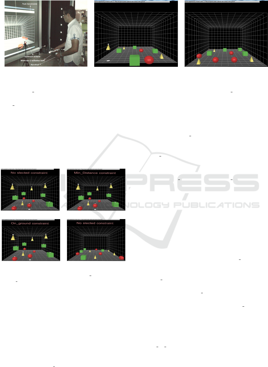
(a) (b) (c)
Figure 5: A subject uses a Wiimote
TM
(a) and shadows (b) to layout the 3D scene (c).
• Minimum distance constraint: participants must
place the objects (except cones) with a distance
d min (2 units) between them.
The assisted task consists of using the solver to
apply constraints on selected objects in order to au-
tomatically lay out the scene. The participants may
select a given object by pressing the A button on the
Wiimote
TM
. This allows the user to view (using the
joystick) and select (Z button) the desired constraint
from a menu and trigger the solver (Fig. 6).
(a) (b)
(c) (d)
Figure 6: A subject selects the Minimum distance (b) and
the On ground (c) constraints using the Nunchuk
TM
, and
finally call the solver for automatic layout (d).
4.1.3 Assisted Simple Task (AS)
In this condition, the same constraints as in the MS
condition were used, but the solver was used to as-
sist the users. Since the constraints should be applied
on all the objects, the participant may adopt different
strategies:
• Strategy 1:
(1) Select one object (cube or sphere or cone),
(2) select the On ground constraint, (3) select
two objects, (4) select the Minimum distance con-
straint and (5) validate the constraint and trigger
the solver for resolution. The same steps should
be repeated for all the remaining objects.
• Strategy 2:
(1) Select all objects (cubes, spheres and cones),
(2) Select the On ground constraint and (3) Val-
idate the constraint and trigger the solver. The
same steps should be repeated for the Mini-
mum distance constraint.
• Strategy 3:
(1) Select all objects (cubes, spheres and cones),
(2) select On ground and Minimum distance con-
straints, (3) validate constraints and launch the
solver.
4.1.4 Assisted Complex Task (AC)
In this condition, the same constraints as in MC con-
dition were used, but the participants had to perform
the layout task using the solver. Similarly to AS, the
participant may adopt different strategies:
• Strategy 1:
(1) Select a cube, (2) Select the Left wall con-
straint constraint, (3) Repeat these steps for the
other 3 cubes. (4) Select a sphere, (5) select the
Right wall constraint constraint, (6) repeat these
steps for the other 3 spheres. (7) Select two cubes,
(8) select the Minimum distance constraint, (9) re-
peat these steps for the other 2 cubes. (10) Select
two spheres, (11) select the Minimum distance
constraint, (12) repeat these steps for the other 2
spheres. (13) Select a cube and a cone, (14) se-
lect the Object on object constraint, (15) repeat
these steps for two other cube and cone. (16)
Select a sphere and a cone, (17) select the Ob-
ject
on object constraint constraint, (18) repeat
these steps for two other sphere and cone. (19)
Validate constraints and launch the solver for res-
olution.
Using Constraint Solver for 3D Layout Assistance in Human-scale Virtual Environment
33

• Strategy 2:
(1) Select all cubes, (2) select the Left wall con-
straint constraint, (3) Select all spheres, (4) se-
lect the Right wall constraint constraint, (5) select
all cubes, (6) select the Minimum distance con-
straint, (7) select all spheres, (8) select the Mini-
mum distance constraint, (9) select a cube and a
cone, (10) select the Object on object constraint
constraint, (11) repeat these steps for two other
cubes and cones. (12) Select a sphere and a cone,
(13) select the Object on object constraint con-
straint, (14) repeat these steps for two other sphere
and cone. (15) Validate constraints and launch the
solver for resolution.
• Strategy 3:
(1) Select all cubes and spheres, (2) select the
Minimum distance constraint, (3) select all cubes,
(4) select the Left wall constraint constraint, (5)
select all spheres, (6) select the Right wall con-
straint constraint, (7) select a cube and a cone, (8)
select the Object on object constraint constraint,
(9) repeat these steps for two other cubes and
cones, (10) select a sphere and a cone, (11) select
the Object on object constraint constraint, (12)
repeat these steps for two other sphere and cone.
(13) Validate constraints and launch the solver for
resolution.
The interaction strategy to perform the tasks has
not been rigorously defined in order to analyze
and study subjects’ preferences. The best strate-
gies were observed and it was determined that
strategy 3 in simple and complex assisted tasks
was chosen by more than 85% of subjects. This
information is very interesting and will help us
improve user interaction.
4.2 Procedure
The overall goal of the study was explained to the
participants, especially about the possibility of con-
trolling the solver during the layout task. Afterwards,
a brief overview of the four tasks was given. Before
starting the study, participants performed a training
session with each task in a randomized order without
recording any data. Each subject was given a set of
information sheets that described the constraints for
each condition. After each experiment, the partici-
pants completed the NASA-TLX questionnaire. To
avoid the learning effect, the tasks were counterbal-
anced. In conditions AS and AC two more ques-
tions were added to assess the participants’ satisfac-
tion and the subjective preference about the solver’s
assistance.
4.2.1 Collected Data
To investigate the effect of the solver integration on
task performance, several measures were utilized that
can be categorized as subjective preference (via ques-
tionnaire) and task performance in terms of comple-
tion time and layout errors.
• Satisfaction. Using a seven-points Likert scale
(i.e., 1 for ”very low” to 7 for ”very high”), sub-
jects were asked to rate their satisfaction of the
layout process and the solution proposed by the
solver. It should be noted that the satisfaction con-
cerns the final proposed solution and not the user
interaction.
• Assistance. Using the same seven-points Likert
scale, subjects were asked to express their opin-
ions about the assistance provided by the solver.
The aim was to know to what extent the solver’s
integration assisted subjects and facilitated the
layout tasks.
It should be noted that these two questions were
not asked in manual tasks (MS and MC) because
the participants lay out the scene themselves with-
out any assistance. In addition, in manual tasks
the subjects placed objects one by one according
to their preferences, unlike the assisted tasks (AS
and AC) where the solver’s decision (computed
solution) does not take their preferences into con-
sideration. For this reason, the question about the
satisfaction is only of interest when the solver is
used (i.e., assisted tasks).
• Workload. Subjects filled out the NASA-TLX
questionnaire to assess their level of workload us-
ing six indices:
- Mental Demands (MD): The mental and per-
ceptual activity required, such as thinking, cal-
culating, deciding, remembering, and looking;
- Physical Demands (PD): The physical activity
required, such as pulling, pushing, turning, and
controlling;
- Temporal Demands (TD): The time pressure
perceived due to the rate or pace at which tasks
or task elements occurred;
- Own Performance (OP): The estimation of suc-
cessfully accomplishing the goals;
- Effort (EF): The effort required to achieve the
task;
- Frustration (FR): The level of discouragement,
irritation and annoyance versus gratification,
contentment, and complacency felt during the
task.
HUCAPP 2017 - International Conference on Human Computer Interaction Theory and Applications
34

• Task Performance. Although the main objective
of the study was to assess to what extent the sub-
jects appreciated the assistance provided by the
solver, objective data (completion time and num-
ber of errors) was also collected. Completion time
is defined as the time between the first pressing on
the B button (Wiimote
TM
) and the moment when
the participant considers the task achieved. Lay-
out error can be evaluated by two parameters:
1. Placement Error: This type of error is not re-
lated to any of the constraints previously de-
scribed. The system checks whether or not each
object was included in the 3D scene (large 3D
cube) based on the x, y, and z coordinates. The
number of occurrences of this error was calcu-
lated for each experimental condition.
2. Distance Error: Since the Minimum Distance
constraint exists in all conditions, the error gen-
erated by the dissatisfaction of this constraint
was calculated. At the end of each task, the sys-
tem calculates the distance between each pair
of objects. If the calculated distance is greater
than the threshold (dmin), the system records
the occurrence of the error.
In addition to these objective data, we also mea-
sured the number of objects selection made by the
participants during tasks. Indeed, the study of this
data reflects the subject’s effort during the tasks.
The number of selection of each 3D object was
calculated for each experimental condition.
5 RESULTS AND DISCUSSION
Since the subjects have different levels of expertise
in video games and VR, a t-test was carried out to
check whether this difference of experience affects
task performance. The subjects were separated into
two groups:
• G1, includes subjects who have experience with
video games/VR (12 subjects).
• G2, includes subjects who have never played
video games (10 subjects).
In order to select the appropriate t-test (for equal
or different variances), an F-test was performed for
the dependent variable (completion time) with the
task complexity level (TCL) and user assistance (UA)
as the independent variables.Table 1 summarizes the
computed p-values of the F-test and the t-test.
According to the obtained p-values for the t-test,
there is no statistical difference between the tested
groups (G1 and G2) and therefore task performance
was not affected by the expertise level of the subjects.
Table 1: The P-values of the F-test and t-test (for all exper-
iment conditions)
MS AS MC AC
F-test 0.245 0.384 0.466 0.185
t-test 0.332 0.357 0.343 0.230
5.1 Objective Results
As stated before, a two-way analysis of variance
(ANOVA) was performed for the dependent variable
with TCL and UA as the independent variables. Ta-
ble 2 summarizes the main effects of the indepen-
dent variables as well as their interaction for the com-
pletion time. TCL and UA significantly affected the
completion time and there were no significant inter-
action effects between them.
Task Completion Time. The results for the TCL
were as expected. Unlike the simple task, in the com-
plex task, subjects had to perform many steps to sat-
isfy the four constraints. Therefore, subjects took
longer to complete the task. Similarly, the UA signif-
icantly affected task completion time. With the first
level of UA (without solver), subjects had to manu-
ally pick and place objects with a required level of
accuracy, which resulted in longer task time.
To assess H3, we calculated and compared the
mean task completion time for each task. Subjects
completed the layout task significantly faster under
condition AS (79.26 sec) than under condition MS
(118.06 sec). Similar results were obtained for MC
and AC: the completion time under condition AC was
significantly shorter (139.46 sec) than for MC (165.99
sec).
The results show that H3 was supported even for com-
plex tasks where the participants need to apply more
constraints on selected objects. The results obtained
for the hypothesis H3 can be explained by the fact that
subjects only needed to select objects and constraints
and trigger the solver. Additionally, subjects didn’t
need to refine the proposed solution since it satisfied
all the constraints. The validation of the H3 shows
that the use of the solver makes it faster and easier for
3D layout tasks compared to the manual method. It
should be noted that the task completion time includes
the time required by the solver to find a solution and
the time for interaction.
Table 2: The main and interaction effects of the indepen-
dent variables on the completion time.
Effect TCL UA TCL × UA
Time p < 0.05 p < 0.05 p = 0.4198
F
1,21
= 18.60 F
1,21
= 50.98 F
1,21
= 0.66
Using Constraint Solver for 3D Layout Assistance in Human-scale Virtual Environment
35

Placement and Distance Errors. When subjects
were assisted (AS and AC), the spatial configuration
proposed by the solver did not contain errors (no
placement and minimum distance errors). Therefore
the system will flawlessly reconfigure the VE. For this
reason, it is not justifiable to compare manual and as-
sisted tasks using these two types of errors. How-
ever, it is interesting to examine these errors in manual
tasks (MS and MC).
Results showed that about 27.27% of manipu-
lated objects were placed partially outside the VE in
MS and about 33.91% in MC. The participants often
failed to respect the minimum distance constraint. In
fact, 21.7% of the objects were placed too close to
each other (< d min) in MS and 16.2% in MC. This
relatively high number of errors was highly dependent
on the visual condition (without stereoscopy) despite
the use of shadows, but it could be reduced by incor-
porating stereo viewing and depth cues (Polys et al.,
2011). The use of the solver completely avoided this
type of error which validates hypothesis H4 concern-
ing the effect of the solver on object placement accu-
racy. These results can be explained by the fact that
the solver satisfies all constraints and correctly places
the objects .
Number of Selection. As previously mentioned,
the number of object selection reflects the subject’s
effort during the tasks. Subjects often selected the
same objects many times in the manual tasks, which
required far more effort than in the assisted tasks. Fig-
ure 7 shows that the average number of selection on
each object (obj0 to obj11) depends on the type of task
(manual or assisted). The subjects made more object
selections in the manual tasks and consequently took
more time. Thus, the use of the solver indirectly re-
duced the overall difficulty by reducing the number of
object selections.
Figure 7: Average number of selections for each object in
each condition.
5.2 Subjective Results
Task Workload. Subjects filled out a NASA-TLX
questionnaire to express their perceived level of work-
load. They were asked to rank each workload index
using a seven-point Likert scale. An ANOVA analysis
was performed to find the effect of the independent
variables (user assistance and task complexity level)
on the workload indexes (MD, PD, TD, OP, EF, FR).
As shown in Table 3, there were no significant
interaction effects between the two independent vari-
ables and no significant effect of TCL on temporal de-
mand, effort and frustration, whereas it significantly
affects the mental, physical demands and their own
performance. Indeed, the complex tasks required a
higher mental and physical demands (Mean
{MD}
=
3.29 and Mean
{PD}
= 2.83) than the simple tasks
(Mean
{MD}
= 2.22 and Mean
{PD}
= 2.18). For their
own performance, a lower score is observed in the
complex tasks (Mean
{OP}
= 5.85) than in the simple
ones (Mean
{OP}
= 6.27).
For the second independent variable (UA), the
results showed a significant effect on all the work-
load indexes. The Table 3 illustrates how partici-
pants found the non-assisted tasks causing a higher
mental, physical and temporal demands (Mean
{MD}
=
3.04, Mean
{PD}
= 3.04 and Mean
{T D}
= 4.93), a
higher level of effort and frustration (Mean
{EF}
=
3.58 and Mean
{FR}
= 2.97), and a lower feeling
of performance (Mean
{OP}
= 5.62) than in the as-
sisted tasks (Mean
{MD}
= 2.47, Mean
{PD}
= 1.97,
Mean
{T D}
= 4.14, Mean
{EF}
= 2.62, Mean
{FR}
=
1.77 and Mean
{OP}
= 6.5).
Satisfaction and Solver Assistance. Subjects were
asked to answer two additional questions about satis-
faction and solver’s assistance. For the satisfaction
level, they assess solutions proposed by the solver
(Fig. 8.a). In condition AS, 20 subjects reported that
they were satisfied with the proposed solution. Two
subjects gave a neutral response and said that the pro-
posed spatial configuration is not optimized although
all of the constraints were satisfied. In condition AC,
16 subjects were either satisfied or very satisfied with
the proposed solution. Only two subjects reported that
the solver had not given the best solution. It is impor-
tant to note that the solver can find many solutions but
only proposes the first one, which is not necessarily
the best according to a subject’s preferences.
Subjects were also asked to evaluate the assis-
tance level provided by the solver over the layout
tasks (Fig. 8.b). In condition AS, 21 subjects reported
that the layout became easier to set up when using the
solver; only one subject did not feel any difference be-
tween manual tasks and the assisted ones. In the AC
condition, all subjects reported that the solver made
the task much easier.
According to the results of workload, satisfaction and
assistance, the hypothesis H1 was supported. In addi-
HUCAPP 2017 - International Conference on Human Computer Interaction Theory and Applications
36
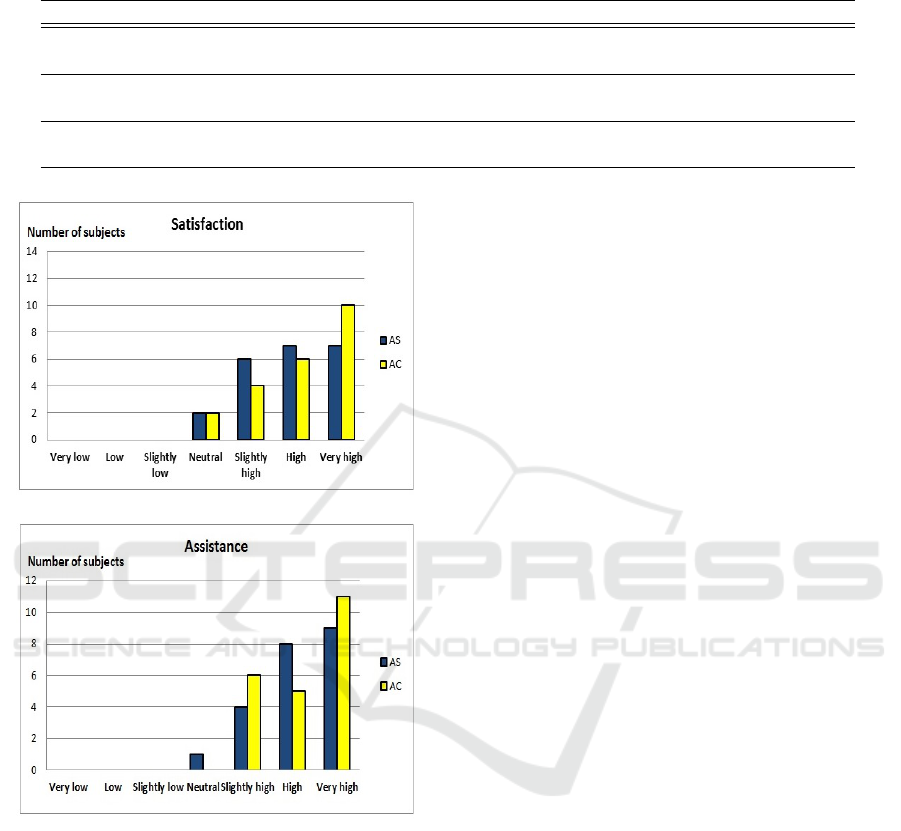
Table 3: The main and interaction effects of the independent variables on the workload indexes (Mental demand (MD),
Physical demand (PD), Temporal Demands (TD), Own Performance (OP), Effort (EF), Frustration (FR).
Effect MD PD TD OP EF FR
TCL p = 0.0001 p = 0.0071 p = 0.703 p = 0.0166 p = 0.2663 p = 0.1025
F
1,21
= 17.64 F
1,21
= 7.58 F
1,21
= 0.15 F
1,21
= 5.95 F
1,21
= 1.25 F
1,21
= 2.72
UA p = 0.0286 p < 0.0001 p = 0.0174 p < 0.0001 p = 0.0018 p < 0.0001
F
1,21
= 4.95 F
1,21
= 20.50 F
1,21
= 5.87 F
1,21
= 26.26 F
1,21
= 10.34 F
1,21
= 18.90
TCL × UA p = 0.9349 p = 0.4272 p = 0.6127 p = 0.6281 p = 0.5788 p = 1.00
F
1,21
= 0.01 F
1,21
= 0.64 F
1,21
= 0.26 F
1,21
= 0.24 F
1,21
= 0.31 F
1,21
= 0.001
(a)
(b)
Figure 8: Satisfaction (a) and subjective feelings of assis-
tance level provided by the solver (b) for conditions AS and
AC.
tion to the benefits of utilizing the solver on task per-
formance, subjects strongly appreciated the provided
assistance.
Interaction Technique Evaluation. Most of the
participants reported that the interaction with the
solver through the proposed technique was easy and
intuitive. However, some subjects had difficulties
identifying and applying the constraints. Some sub-
jects reported that the selection of objects upon which
constraints were to be applied was slightly tedious.
This is due to the fact that some subjects have chosen
one of the least effective strategies to interact with the
system.According to these results, the hypothesis H2
was moderately supported. The low satisfaction of
this hypothesis shows that although the solver assis-
tance satisfied the subjects and made the 3D layout
easier, the interaction protocol is not yet optimized
and requires some improvements. This difficulty is
inherent to the proposed interaction technique. This
lack of accuracy also affected task performance be-
cause subjects had to push the B button several times
to select a given object. Similarly, the use of the
Nunchuk
TM
to select and apply constraints was con-
sidered slightly difficult. Subjects needed to navigate
in the constraint menu before finding the desired one.
This problem could be reduced by more intuitive in-
teraction techniques based on multi-modality (for ex-
ample introducing voice commands to select objects
and constraints).
6 CONCLUSION AND FUTURE
WORK
The main goal of the study was to propose a combina-
tion of virtual reality and constraint programming to
simulate layout tasks and assist users. Both subjective
and objective effects of the solver integration were in-
vestigated by comparing manual versus assisted tasks
for two levels of difficulty. Four conditions were pro-
posed: MS (manual simple task), AS (assisted sim-
ple task), MC (manual complex task) and AC (as-
sisted complex task). The results indicated that the
use of the solver reduced both the number of object
selections and errors, regardless of the level of the
task’s difficulty. The results also revealed that par-
ticipants peroformed the layout task faster when the
solver was used. Most of the subjects reported that
the solver was useful and assisted them with complet-
ing layout tasks and they were generally satisfied by
the proposed solution. Both objective and subjective
data also showed that the proposed interaction tech-
nique has some shortcomings. In order to improve
Using Constraint Solver for 3D Layout Assistance in Human-scale Virtual Environment
37

interaction with the solver, we propose that future de-
signs use a multimodal approach based on gestures
and voice commands which facilitate the selection
and validation of constraints (solver control) and/or
objects. We are currently developing a specific appli-
cation jointly with industrial partners. This applica-
tion involves real objects and specific constraints.
REFERENCES
Calderon, C., Cavazza, M., and Diaz, D. (2003). A new
approach to the interactive resolution of configuration
problems in virtual environments. Lecture notes in
computer science, 2733:112 – 122.
Drieux, G., Guillaume, F., Leon, J., and Chevassus, N.
(2005). Samira: A platform of virtual mainte-
nance simulation with haptic feedback incorporating
a model preparation process. In Proceedings of Vir-
tual Concepts.
Essabbah, M., Bouyer, G., and Otmane, S. (2014). A
framework to design 3d interaction assistance in
constraints-based virtual environments. Virtual Real-
ity, 18(3):219–234.
Fages, F., Soliman, S., and Coolen, R. (2004). Clpgui:
A generic graphical user interface for constraint logic
programming. Constraints, 9:241 – 262.
Fernando, T., Murray, N., Tan, K., and Wimalaratne, P.
(1999). Software architecture for a constraint-based
virtual environment. Proceedings of the ACM sympo-
sium on Virtual reality software and technology, pages
147–154.
Fruhwirth, T. and Abdennadher, S. (2003). Essentials of
constraint programming. Springer Verlag.
Jacquenot, G. (2009). Mthode gnrique pour l’optimisation
d’agencement gometrique et fonctionnel. Thse de
Doctorat, Ecole Centrale de Nantes.
Marriott, K., Moulder, P., Stuckey, P. J., and Borning, A.
(2001). Solving disjunctive constraints for interactive
graphical applications. In CP, pages 361–376.
Medjdoub, B. (2004). Constraint-based adaptation for
complew space configuration in building services.
Journal of Information Technology in Construction,
243(2007):627–636.
Merrell, P., Schkufza, E., Li, Z., Agrawala, M., and Koltun,
V. (2011). Interactive furniture layout using interior
design guidelines. ACM Trans. Graph., 30(4):87–95.
Messinger, P. R., Stroulia, E., Lyons, K., Bone, M., Niu,
R. H., Smirnov, K., and Perelgut, S. (2009). Virtual
worlds past, present, and future: New directions in so-
cial computing. Decision Support Systems, 47(3):204
– 228.
OptiTrack (2011). Optical motion capture systems and
tracking software, http://www.naturalpoint.com/ opti-
track/.
Polys, N. F., Bowman, D. A., and North, C. (2011). The
role of depth and gestalt cues in information-rich vir-
tual environments. Int. J. Hum.-Comput. Stud., 69(1-
2):30–51.
Richard, P., Chamaret, D., Inglese, F., Lucidarme, P., and
Ferrier, J. (2006). Human-scale virtual environment
for product design: Effect of sensory substitution.
IJVR.
Sanchez, S., Roux, O. L., Inglese, F., Luga, H., and Gail-
dart, V. (2002). Constraint-based 3d-object layout us-
ing a genetic algorithm.
Smelik, R., Galka, K., Kraker, K. J. D., Kuijper, F., and
Bidarra, R. (2011). Semantic constraints for procedu-
ral generation of virtual worlds. volume 1, page 9.
Sutherland, I. E. (1964). Sketch pad a man-machine graph-
ical communication system. In Proceedings of the
SHARE design automation workshop, pages 329–346,
New York, NY, USA. ACM.
Theodosiou, G. and Sapidis, N. S. (2004). Information
models of layout constraints for product life-cycle
management: a solid-modelling approach. Computer-
Aided Design, 36(6):549–564.
Tim, T., Rafael, B., Ruben, M. S., and Klaas, J. K. (2009).
Rule-based layout solving and its application to proce-
dural interior generation. In Proceedings of the CASA
workshop on 3D advanced media in gaming and sim-
ulation (3AMIGAS), pages 212–227.
Xu, K., Stewart, J., and Fiume, E. (2002). Constraint-
based automatic placement for scene composition. In
Graphics Interface Proceedings, University of Cal-
gary.
Zorriassatine, F., Wykses, C., Parkin, R., and Gindy, N.
(2003). A survey of virtual prototyping techniques
for mechanical product development. Journal of En-
gineering Manufacture, page 217.
HUCAPP 2017 - International Conference on Human Computer Interaction Theory and Applications
38
