
Multi-view ToF Fusion for Object Detection in Industrial Applications
Inge Coudron and Toon Goedem´e
EAVISE Research Group, KU Leuven, Jan Pieter De Nayerlaan 5, Sint-Katelijne-Waver, Belgium
{inge.coudron, toon.goedeme}@kuleuven.be
Keywords:
Extrinsic Calibration, Multi-sensor, Object Detection.
Abstract:
The use of time-of-flight (ToF) cameras in industrial applications has become increasingly popular due to the
camera’s reduced cost and its ability to provide real-time depth information. Still, one of the main drawbacks
of these cameras has been their limited field of view. We therefore propose a technique to fuse the views
of multiple ToF cameras. By mounting t wo cameras side by side and pointing them away from each other,
the horizontal field of view can be artificiall y extended. The combined views can then be used for object
detection. The main advantages of our technique is that the calibration is fully automatic and only one shot of
the calibration target is needed. Furthermore, no overlap between the views is required.
1 INTRODUCTION
Object detection remains an important challenge in
industry. In ma ny of these applications, a la rge scene
area needs to be covered. Hence a camera with a wide
field of view is usually required. Since the field o f
view of a single ToF camera is limited, multiple ca-
meras mu st be com bined. This requires to first cali-
brate the rela tive poses (i.e. extrinsic paramete rs) of
the cameras.
Once the data from the different cameras is trans-
formed into a common reference frame, it can be fed
to the object detection framework. A popular appro-
ach to the 3D object detection problem is to exploit
range images (Bielicki and Sitnik, 2013). These ima-
ges make data processing significantly faster, as they
convert the mo st time-consuming tasks (e.g ., nearest
neighbor search) from a 3D space into a 2D space. We
will there fore rende r the registered point clouds with
a virtua l camera to simulate a depth sensor.
In this paper, we present a convenient extern al ca-
libration method for a multi-ToF system. That is to
say, the human interaction and export knowledge re-
quired for the calibration is kept to a minim um. The
views from the different ToF camera s c an be merged
into an extended range image usable for 3D object
detection. The remainde r of this paper is organized as
follows. Firstly, the Related Work section provides an
overview of existing calibration techniques. Section 3
introdu ces our app roach for multi-view TOF fusion.
Experiments in section 4 show the accuracy in cali-
bration. Finally, a short conclusion is given.
2 RELATED WORK
The calibr ation of mu ltiple cameras is a well-studied
problem in computer vision. The most co mmon met-
hod for calibrating conventional intensity cameras is
to use a checkerboard which is obser ved at different
positions and orie ntations within the cameras shared
field of view (Zhang , 2000). Given the image coor-
dinates of the reference po ints (i.e., the checkerboard
corners) and the g eometry of the checkerboard (i.e. ,
the numb e r of squares and the squa re dime nsion), the
camera parameters can be estimated using a closed
form so lution w.r.t. the pinhole camera model. An ite-
rative bundle adjustment algorithm can then be used
to refine the parameters. The same stand ard technique
could be used for ToF cameras as well, as they pro-
vide an amplitude image associated with each range
image. However, the low resolution of the amplitude
images makes it difficult to detect the checkerboard
corners reliably resulting in ina ccurate c alibration.
To overcome this limitation, other methods have
been proposed that work directly on 3D shapes. Au-
vinet et al. (Auvinet et al., 2012), for example, use
the intersection points of triplets of plane s as ref e-
rence points. The equation of each plane can be cal-
culated by using a singular value decomposition of
points lying on the plane. Given the sets of co rre-
sponding reference points, the rigid body transfo rma-
tion between the pair of cameras is estimated in a le-
ast square sense. Another method presented by Ruan
et al. (Ruan and Huber, 2014), u ses the centers of a
spherical calibration target as reference poin ts. The
Coudron I. and GoedemÃl’ T.
Multi-view ToF Fusion for Object Detection in Industrial Applications.
DOI: 10.5220/0006136802030207
In Proceedings of the 12th International Joint Conference on Computer Vision, Imaging and Computer Graphics Theory and Applications (VISIGRAPP 2017), pages 203-207
ISBN: 978-989-758-225-7
Copyright
c
2017 by SCITEPRESS – Science and Technology Publications, Lda. All rights reserved
203
spherical target has the advantage that it is rotation
invariant. However, the extraction of the center of the
sphere f rom a noisy p oint cloud is le ss robust, sinc e
the ac tive illumination will be mostly scattere d away
by the spherical surface. Furthermore, note that these
methods still require a significant amount of human
operation, since the calibratio n target must be moved
and matched in many different positions.
Alternatively, a method that takes only one pa ir of
3D images is the Iterative Closest Point (ICP) algo-
rithm (Besl and McKay, 19 92). The ICP algorithm
has been widely used for 3D registration. The ri-
gid bo dy transformation between two point clouds is
estimated by minimizing the distance from a point
in one cloud to the closest point in the other c loud.
A popular variant of this method minimizes the dis-
tance b etween a point an d the tangent plane at its cor-
respond ence point in stead. The point-to-plane error
metric usually performs better in structured e nviron-
ments (Low, 2004 ). One o f the advantages of this
algorithm is that in contrast to the first algorithm, it
does not rely on local fe ature extraction. Unfortuna-
tely, the ICP algorithm requir es sufficient overlap be-
tween the point clouds to succ eed (Chetverikov et a l.,
2002). Hence, at first sight, it might not seem like
an appropriate method for the artificial extension of
a ToF camera’s field of view addre ssed in this work.
We will h owever show that using a proper calibration
target, the metho d contributes to an easy to use cali-
bration tool.
3 MATERIALS AND METHODS
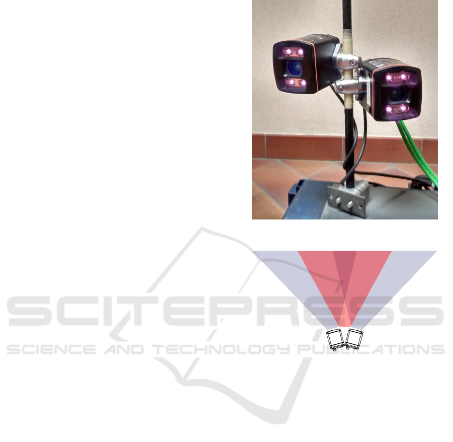
3.1 Camera Set-up
The camera set- up is depicted in 1. Two IFM Efec-
tor O3D303 ToF cameras are mounted side by side
and pointing away from each other to artificially ex-
tend the field of view as can be seen in figure 2. The
red trian gle depicts the field of view that would have
been covered if a single ToF camera was placed in the
middle. As c an be seen in this figure, a small area at
the bottom is not covered. Th is is not necessarily a
problem since the minimum operatin g distance must
be respected anyway. With two cameras, the grey area
that is covered depends on the angle be tween the ca-
meras. Increasing the angle, further extends the area
covered. However, this also implies that th e unco -
vered area in the middle enlarges. Hence a trade-
off must be made depending on the desired operating
range.
To be able to fuse the data from the different ca-
meras, it is important that the images are captur ed sy-
Figure 1: Camera set-up.
Figure 2: Artificially extended field of view.
nchronously. This can be achieved by cascading the
cameras via hardware trigger. The first camera will
automatically trigger the second camer a after com-
pletion of the imag e capture . However, if both came-
ras are operating on the same active illumination fre-
quency measur ement errors may occur due to m utual
interference from simultaneous exposure (see Fig. 3).
By setting the cameras on a different frequency chan-
nel the occurrence of measurement errors can be re -
duced. Both ca meras are connected to a single GigE
port throug h a switch.
3.2 External Calibration
To determine the rigid body transformation between
two point clouds, 6 degrees of freedom (DoF) need
to be eliminated. In theory, a set of 4 non-coplanar
referenc e points is sufficient. Nevertheless, it is best
to use as many points as possible to increase the re-
liability of the transformation found. As such, a ca-
libration target is defined using geometric primitives
VISAPP 2017 - International Conference on Computer Vision Theory and Applications
204
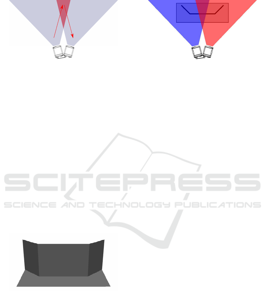
Figure 3: Mutual interference by ToF cameras during si-
multaneous operation with the same active illumination fr e-
quency.
that eliminates all DoFs. Possible primitives are a
sphere eliminating 3 DoF (viz. three translations), a
plane eliminating 3 DoF as well (viz. one translation
and two rotation s) and others. In this work, we will
use a calibration target with multiple planar regions.
The motivation for this selection is tha t p la nes c a n be
acquired more reliably with a ToF camera than shapes
with varying normals such as spheres.
The main idea behind our approac h is that we do
not directly register the two ToF views with each ot-
her. Instead, each camera individually registers o nly
to th e observed part of the calibration target using
the ICP algorithm. Since both parts of the calibra-
tion target are defined in the same co ordinate system,
the point clouds a re transformed into a common refe-
rence frame a nd the extrinsic parameter s between the
cameras can be derived. The proposed calibration tar-
get ca n be seen in Fig. 4. The calibration target is split
into two parts, one that is observed by the left camera
and one by the right camera (see Fig. 5).
Figure 4: CAD model of the calibration target.
A few considerations still need to be addressed.
First of all, the ICP algorithm is a local registration
method, meaning tha t an initial estimation of the glo-
bal tr ansformation is necessary to obtain a good re-
sult. Chances are otherwise that the algorithm will get
stuck in local minima. Secondly, the input dep th data
is transformed to match the calibration model and
not vice versa. Th irdly, due to the p la nar geometry
of the calibration target, the po int-to-plane distance
Figure 5: Calibration target as seen by each camera.
will provide a mor e robust error metric than the stan -
dard point-to-point distance. Lastly, since ToF came-
ras suffer from multi-path interference, edges might
be represented inaccurately. Therefore, the edges are
eroded in the actual calib ration model.
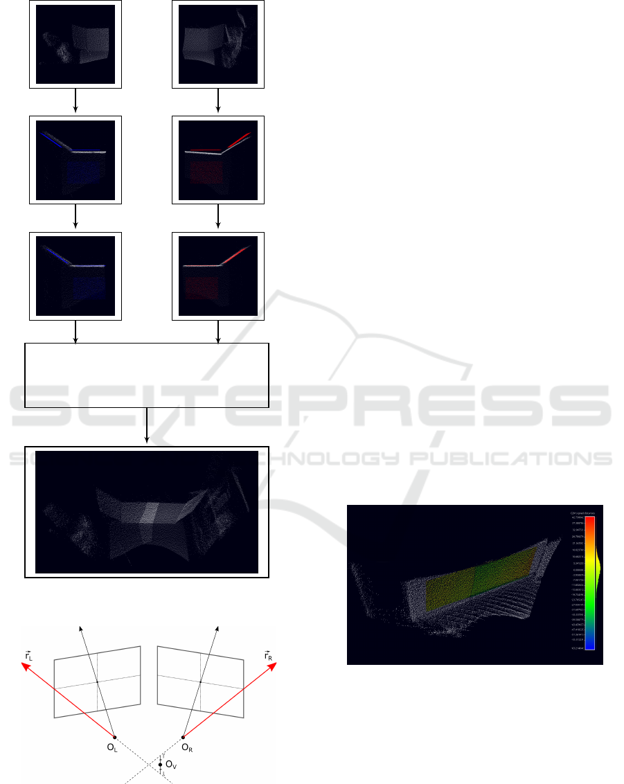
A complete overview of the calibration method is
shown in figure 6. An initial estimate of the transfor-
mation matrix is obtain e d by mea suring the distance
between either c a mera and the corresponding ca libra-
tion part, and taking into a ccount the angle between
the two c a meras. Next, th e ICP algorithm is per for-
med to refine these transfor mation estimates. Since
both calibration par ts are referenced in a comm on
coordinate system, the rigid transformation from one
camera to the other can be derived. The data from the
different cameras can now be fused together.
3.3 Data Fusion
The main g oal of data fusion is to comb ine the data
from the To F camer a s such that it can be used by
an obje ct detection framework. The registered point
clouds could simply be summed into a larger point
cloud. However, the core of our de te ction framework
is based on 2D detection methods for computational
reasons. Therefore , the combined point cloud must be
projected onto an image plane. The simple and well-
known pinhole camera model is used to describe the
3D to 2D projec tion. To make sure that the com plete
point cloud fits on the image plane, appropriate mode l
parameters must be selected.
First of all, a single viewpoint is defined for the
virtual camera. This viewpoint is chosen such that
the horizontal field of view of the virtual camera mat-
ches the co mbined horizontal field of view of the ToF
cameras as can be seen in figure 7. Consequently,
the virtual camera is placed at the intersection of the
horizontal boundary field of view vectors. However,
since the ToF cameras are not perfectly aligned, the
viewing rays will not intersect. Therefor e the inter-
section p oint is calc ulated as the point that minimizes
the distance to each ray.
Next the intrinsic parameters of the virtual camera
Multi-view ToF Fusion for Object Detection in Industrial Applications
205
Left camera C
L
Right camera C
R
T
EST
L
T
ICP
L
T
EST
R
T
ICP
R
Transformation matrix fro m C
L
to C
R
:
T = T
−1
EST
R
T
−1
ICP
R
T
ICP
L
T
EST
L
Figure 6: Overview of the calibration method.
Figure 7: Sensor origin of the virtual camera.
are chosen in accordance with the original ToF ca-
meras. Based on the extrinsic p arameters between
the two ToF cam eras the angle of view can be esti-
mated. The focal length of the ToF camera is main-
tained. Since the angle of view and foca l length are
now fixed, the resolution o f the image plane is fixed as
well. Each point in the point cloud is then projected
on the camera image using the pinhole camera model.
This way a range image is obtained that can be used
for object detection as shown in the next section.
4 RESULTS
4.1 Registration Experiment
To obtain an idea of the accuracy of the calibration,
the camera-setup was pointed towards a wall. Using
the meth od described previously, the point clouds
were combined into a range image. Next a plane was
fitted to the wall. In figure 8, the difference between
each point of the wall and the mesh representation of
the plane is shown. The color indicates the distance
between the fitted p la ne and wall. When the distance
is small, the point is co lored green. The histogram
has a Gaussian distribution due to the noisy nature
of the range data itself. The root mea n square error
between th e fitted plane and wall is 9.84mm, which
correspo nds to the relative accuracy of the camera. If
there would have been a discrepancy between both
due to incorrect calibration, th e n the histogra m would
have been more skewed or have outliers.
Figure 8: Accuracy of the calibration.
4.2 Application Example
Existing 3D object detection methods can be slow
due to the 3D complexity (Abbeloos and Goedem´e,
2016). The c ore idea of our obje c t detec tion frame-
work is therefore to reduce the 3D problem into a 2D
space. The work flow of our object d etection frame-
work is shown in figure 9. Firstly, the point clouds
VISAPP 2017 - International Conference on Computer Vision Theory and Applications
206
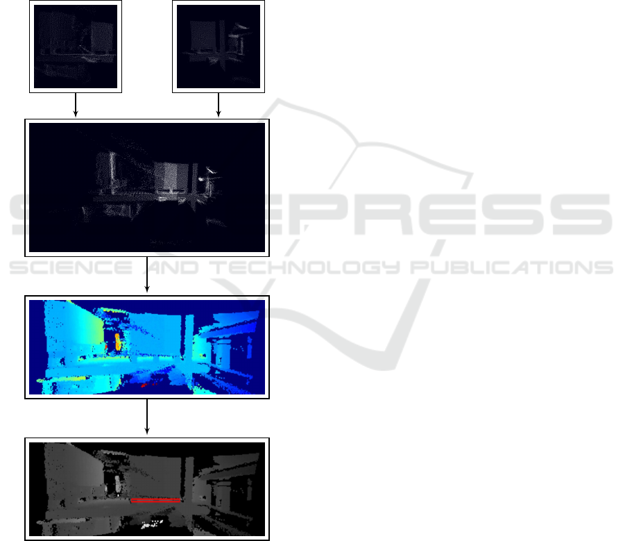
are merged using the extrinsic para meters obtained
during calibration. Then th e combined point clou d
is projected onto a ra nge image. Using a template
matching technique ( e.g. LINEMOD (Hinterstoisser
et al., 2012) ), the object ca n be detected in the range
image. Lastly, all 2D detection results can be re-
projected back into 3D space for an object location
refinement. Eac h 2D detection provide s two coord i-
nates, while the third coordinate is estimated from the
available de pth inform ation. The pose r e finement can,
for example, b e ac hieved with the ICP algorithm.
Left camera C
L
Right camera C
R
3D transformation
3D-2D projection
2D detection
Figure 9: Object detection in an industrial application.
5 CONCLUSIONS
We proposed an accurate and ea sy-to-use technique
for extrinsic calibration of two ToF cameras that are
placed side-by-side with only a small overlap between
the views. We demonstrated that using only a part of
the calibration target in each view, ICP can be used to
register both views despite the limited overlap. The
calibration target that has been used consists of four
planar region s. This has the benefit that it is mo re ro-
bust to noisy range data. Furthermore, for the calibra -
tion only one shot of the c alibration target is requ ired.
The effectiveness of our method was also proven in a
real-life application.
REFERENCES
Abbeloos, W. and Goedem´e, T. (2016). Point pair feature
based object detection for random bin picking. In Pro-
ceedings CRV 2016, number accepted. University of
Victoria.
Auvinet, E., Meunier, J., and Multon, F. (2012). Multi-
ple depth cameras calibration and body volume recon-
struction for gait analysis. In Information Science,
Signal Processing and their Applications (ISSPA),
2012 11th International Conference on, pages 478–
483. IEEE.
Besl, P. J. and McKay, N. D. (1992). Method for registration
of 3-d shapes. In Robotics-DL tentative, pages 586–
606. International Society for Optics and Photonics.
Bielicki, J. and Sitnik, R. (2013). A method of 3d ob-
ject recognition and localization in a cloud of points.
EURASIP Journal on Advances in Signal Processing,
2013(1):1.
Chetverikov, D., Svirko, D., Stepanov, D., and Krsek, P.
(2002). The trimmed iterative closest point algorithm.
In Pattern Recognition, 2002. Proceedings. 16th In-
ternational Conference on, volume 3, pages 545–548.
IEEE.
Hinterstoisser, S ., Cagniart, C., Ilic, S., Sturm, P., Navab,
N., Fua, P., and Lepetit, V. (2012). Gradient response
maps for real-t ime detection of textureless objects.
IEEE Transactions on Pattern Analysis and Machine
Intelligence, 34(5):876–888.
Low, K.-L. (2004). Linear least-squares optimization for
point-to-plane icp surface registration. Chapel Hill,
University of North Carolina, 4.
Ruan, M. and Huber, D. (2014). Cal ibration of 3d sensors
using a spherical target. I n 2014 2nd International
Conference on 3D Vision, volume 1, pages 187–193.
IEEE.
Zhang, Z. (2000). A flexible new technique for camera ca-
libration. IEEE Transactions on pattern analysis and
machine intelligence, 22(11):1330–1334.
Multi-view ToF Fusion for Object Detection in Industrial Applications
207
