
CSG Ray Tracing Revisited: Interactive Rendering of Massive Models
Made of Non-planar Higher Order Primitives
Seyedmorteza Mostajabodaveh
1,2
, Andreas Dietrich
1,2
, Thomas Gierlinger
1,2
, Frank Michel
1,2
and Andr
´
e Strok
1,2
1
Fraunhofer IGD, Darmstadt, Germany
2
Technische Universit
¨
at Darmstadt, Darmstadt, Germany
Keywords:
Real-time Rendering, Rendering Algorithms, Image-based Rendering.
Abstract:
In many scientific and engineering areas, CAD models are constructed by combining simple primitives using
Boolean set operations. Rendering such a dataset usually requires a preprocess, where the surface of the CAD
model is approximated by an often highly complex triangle mesh.
Real-time ray tracing provides an alternative to triangle rasterization as it allows for the direct visualization
of (higher-order) solid and planar primitives without having to triangulate them. Additionally, Boolean com-
positing operations can be performed implicitly per ray, primitives have low storage requirements, and curved
surfaces appear pixel-accurate. In this paper we demonstrate these properties using massive real-world CAD
models.
1 INTRODUCTION
Although constructive solid geometry (CSG) is one
of the oldest techniques for modeling solid objects,
it is still found in CAD packages due to its intuitive
concept. Complicated solid objects are constructed
by combining simple solid primitives using Boolean
set operators (typically union, intersection, and differ-
ence). While CSG is often applied to model solids, it
is rarely found in rendering systems. Rather than di-
rectly rendering CSG primitives and composites, such
models are usually preprocessed and converted into a
surface representation, most often a triangle mesh, as
it can be efficiently rendered on current graphics hard-
ware. This is a viable approach for small and mid-size
scenes. However, for complex datasets, preprocessing
can become prohibitively time consuming, moreover
it can result in a huge number of triangles, potentially
too many to fit into GPU memory.
An alternative is to directly ray trace complex
CSG models (Glassner, 1989). With the public avail-
ability of real-time ray tracing frameworks, such
as NVIDIA’s OptiX (Parker et al., 2010) or Intel’s
Embree (Wald et al., 2014), it has become feasible to
ray trace even huge CAD models at interactive frame
rates. Additionally, these frameworks scale to multi-
ple GPUs (NVIDIA Optix) or CPUs (Intel Embree)
which is a big advantage compared to rasterization
frameworks. Our CSG ray tracing approach has a
number of attractive benefits:
On-the-fly Compositing. Boolean set operations are
performed on a per-ray basis immediately during
rendering. It is therefore not necessary to ap-
ply them in a preprocess, which enables the user
to change the set operators while inspecting the
scene.
Low Storage Requirement. Since no a priori trian-
gulation of primitives is necessary, they can be
described by a small set of parameters. For ex-
ample, for a cylinder only height and radius need
to be stored. (Additionally a transformation ma-
trix may be needed, but it is not always required
to store a full 4 × 4 matrix as we will see further
below.) This enables holding scenes in memory,
which would not fit in a triangulated form (see
Figure 1).
Pixel-accurate Higher Order Surfaces. Higher or-
der primitives, such as cylinders or tori, can be
directly tested for intersection with a ray by solv-
ing the appropriate equations without having to
triangulate first. Consequently, no discretization
artifacts are visible, and curved surfaces appear
perfectly smooth (see Figure 5).
The main contribution of this paper is to present a
method to apply CSG operations in real-time during
258
Mostajabodaveh S., Dietrich A., Gierlinger T., Michel F. and Stork A.
CSG Ray Tracing Revisited: Interactive Rendering of Massive Models Made of Non-planar Higher Order Primitives.
DOI: 10.5220/0006136402580265
In Proceedings of the 12th International Joint Conference on Computer Vision, Imaging and Computer Graphics Theory and Applications (VISIGRAPP 2017), pages 258-265
ISBN: 978-989-758-224-0
Copyright
c
2017 by SCITEPRESS – Science and Technology Publications, Lda. All rights reserved
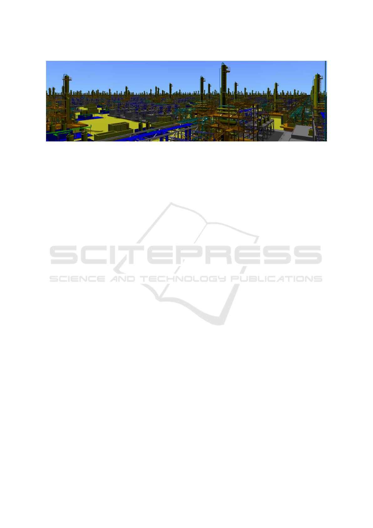
Figure 1: A complex CAD scene built out of 8,000 individual plant models. In total, the scene consists of more than
100,000,000 non-planar second-order (cylinders, cones, etc.) and forth-order (tori) primitives, ray traced at more than
10 frames per second on 16 CPU cores, including pixel-accurate shadows.
ray tracing while keeping the memory overhead low.
Additionally, we have evaluated this method in com-
parison to two well-known rasterization-based CSG
operation techniques: (Goldfeather et al., 1986) and
(Stewart et al., 2002).
Structure of the Paper. In chapter 2, related work
to our approach is described. In chapter 3, our CSG
ray tracing approach and its implementation using
NVIDIA Optix (Parker et al., 2010) is described.
In chapter 4, the proposed ray tracing approach is
compared to rasterization-based CSG rendering ap-
proaches (Goldfeather (Goldfeather et al., 1986) and
SCS (Stewart et al., 2002)). Additionally, we describe
our experiences of applying real-time CSG ray tracing
to models from two different domains. The first one
is a complex IC package of a Cell Broadband Engine
chip. The second one is a collection of plant mod-
els described in the AVEVA PDMS 3D model for-
mat (RVM). Conclusions of the paper are presented
in chapter 5.
2 RELATED WORK
An early algorithm for directly ray tracing CSG ob-
jects without extracting a surface mesh was presented
by Roth (Roth, 1982). It computes ray–object inter-
section intervals and combines them using Boolean
operations. Our approach is similar to this paper.
However, we benefit from state-of-the-art ray tracing
techniques and utilize today’s modern parallel graph-
ics and central processors. Later (Goldfeather et al.,
1986) demonstrated how to directly render CSG mod-
els using a depth-layering Z-buffer approach. The
number of render passes required in this method is
of O(n
2
) complexity where n is the number of prim-
itives. The required number of draw calls for this
method is similarly of subquadratic order. (Wiegand,
1996) implements a GPU accelerated version of this
algorithm. (Stewart et al., 2002) introduces an image-
based Sequence Convex Subtraction(SCS) algorithm
utilizing depth and stencil buffer to render CSG mod-
els. While this approach only supports convex primi-
tives, it can render the CSG model in a constant num-
ber of passes. The drawback of this method is its
large number of required draw calls to achieve the cor-
rect stencil and depth buffer values which is of sub-
quadratic order w.r.t the number of primitives. (Guha
et al., 2003) devised an algorithm which uses depth
and stencil buffers to perform depth peeling (Everitt,
2001) which peels off the model layers and perform
CSG operations on the fly. For every peeled layer,
it tests if the pixels belong to the final result. If a
result pixel was found, the pixel is masked for the
next peeling steps to reduce the computation load.
The number of passes for this method is still de-
pendent on the number of primitives which causes
a performance drop when being applied to massive
CSG models. (Hable and Rossignac, 2005) combines
depth peeling and a linear formulation of Boolean ex-
pressions to render CSG models. It depth peels the
scene while performing CSG operations from front-
to-back. The objects need to be drawn in k stages,
where k is the scene’s number of depth-layers. As
massive and complex scenes are made of a tremen-
dous number of layers (e.g. for doing CSG opera-
tions on a PCB board made of many different lay-
ers), this method will have a significant performance
drop. More recently, Romeiro et al. (Romeiro et al.,
2006) used a combination of spatial subdivision and
ray tracing methods to render massive CSG models.
They tried to construct a simple Octree containing the
CSG tree which can be used for rendering the model
correctly. As this method ends up with a huge number
of draw calls, it can distribute the workload properly
on CPU and GPU for small enough models. How-
ever, the CPU will limits the GPU rendering for han-
CSG Ray Tracing Revisited: Interactive Rendering of Massive Models Made of Non-planar Higher Order Primitives
259

dling massive models. In 2010 Hijazi et al. (Hijazi
et al., 2010) interactively ray traced CSG objects de-
fined as implicit functions using interval arithmetic.
(Engel, 2014) presents a two stage procedure to ren-
der deformable meshes made by CSG operations. In
the first stage, the fragments are collected into a big
enough constantly allocated buffer, and in the second
stage, they are sorted by depth and CSG operations
are applied per-pixel. This method requires a huge
amount of memory to store the whole fragments in
the first stage. The size of buffer can exceed the avail-
able GPU memory, e.g. for PCB board models which
contain a lot of different levels of primitives overlap-
ping each other.
3 CSG RAY TRACING
When modeling a scene with CSG techniques, sim-
ple objects, such as boxes, cylinders, tori, etc., form
more complex objects by applying Boolean set opera-
tions, where the basic operators are union, difference,
and intersection. (Although we will here use solids
the concept is also applicable to the combination of
2D objects.) A compound object can be described by
means of a binary tree, where the leaves correspond
to primitives and the inner nodes to set operations.
3.1 Interval Evaluation
Ray tracing such a structure can be done in a straight-
forward way. For each ray all the intersection points
of the ray with the primitives of the scene are calcu-
lated. This leads to a set of intervals that determine the
ranges where a ray runs inside or outside of a prim-
itive. These intervals can be grouped in a so-called
Roth diagram (Roth, 1982). Here, for each primitive
that was pierced by the ray, all entry and exit points
are recorded in a sorted order. For each two primitives
that are to be combined, the intervals in the Roth di-
agram are merged according to the relevant Boolean
operation. The resulting Roth diagram, i.e, the result-
ing intervals, represent the entry and exit points of the
composite object. The entry point with the closest dis-
tance to the ray origin represents the eventual hitpoint
(i.e., the nearest surface point which is visible).
3.2 Optimized Hitpoint Calculation
Obviously, for scenes with millions of primitives this
can result in a high number of intervals. While the
amount of memory required to store these intervals
may be negligible for a single ray, it can become pro-
hibitive on GPUs (or many-core architectures in gen-
eral) where hundreds of thousands of rays may be
traced in parallel.
In order to avoid having to compute and store all
intersection intervals along a ray, we take advantage
of the structure of our scenes. Similar to depth peel-
ing, from the camera perspective the CSG model is or-
ganized into a number of layers L
i
(i = 1, ..., l). Each
layer is composed of a number of positive solids P
i, j
( j = 1,..., p
i
) and negative solids N
i,k
(k = 1, ..., n
i
).
We will refer to the negative solids as cutouts in the
following. Thus, the CSG operations for a scene S can
be described as
S =
l
∑
i=1
L
i
with L
i
=
p
i
∑
j=1
P
i, j
−
n
i
∑
k=1
N
i,k
where + and − denote union and difference set op-
erations, respectively. Basically, a layer can be seen
as the difference of two compound (positive and neg-
ative) objects. Because of this, CSG ray tracing a sin-
gle layer can be done by tracking when a ray runs
within a positive or negative medium. To this end, we
employ two counters (posDepth and negDepth) that
are attached as custom parameters to each ray. When-
ever the ray tracer finds the closest intersection of a
ray with the primitives of a layer, a hit program is
called which is illustrated in algorithm 1.
Algorithm 1: RayTraceLayer(ray).
ray: current ray hitting a primitive
1: if entering primitive then
2: delta := +1;
3: else
4: delta := −1;
5: end if
6:
7: if positive primitive hit then
8: ray.posDepth += delta;
9: else
10: ray.negDepth += delta;
11: end if
12:
13: if (ray.posDepth > 0) && (ray.negDepth <= 0)
then
14: ReportHit(); // final hit in layer found
15: else
16: ContinueRay(ray); // still inside a negative
medium
17: end if
Each time a ray enters or leaves a positive or nega-
tive primitive, the counters are increased or decreased,
respectively. In case we are inside a positive medium,
GRAPP 2017 - International Conference on Computer Graphics Theory and Applications
260

but not inside a negative medium, we found the cor-
rect hitpoint corresponding to a layer. Otherwise ray
traversal continues using the updated counters.
To find the final global hitpoint in the scene, a pri-
mary ray is sequentially tested against all layers, and
from the set of layer hitpoints the nearest one is ac-
cepted as final position for shading. In the scene graph
used by the ray tracing engines, the layers of a scene
can be stored as independent sub-trees, which can be
intersected separately.
3.3 Implementation
The heart of a ray tracer is its acceleration struc-
ture. We have used the Bounding Volume Hierar-
chy (BVH) (MacDonald and Booth, 1990) accelera-
tion structure as it provides better performance for our
CSG models than other available acceleration struc-
tures. To exploit multi-threaded acceleration structure
construction in NVIDIA Optix (Parker et al., 2010),
its scenegraph is constructed in correspondence to the
binary tree description of the CSG operations. As we
described in the last section, the ray definition needs
to be extended to store depth of positive and negative
primitives intersections. Nvidia Optix (Parker et al.,
2010) provides a rtcDeclare macro to attach addi-
tional information to a ray definition. When a ray–
primitive intersection is reported, the shading func-
tion is executed. The shader is implemented accord-
ing to algorithm 1. The primitives supported by our
implementation are shown in figure 4.
The ray–primitive intersection test is calculated
with 32-bit floating point operations for all primi-
tives robustly except the circular torus where inter-
section test equation is quartic; while this equation
type can be solved in constant time (Abramowitz,
1974), achieving a robust solution demands double-
precision calculation. Furthermore, the accumulation
buffer (Haeberli and Akeley, 1990) is used to remove
artifacts from the final result image when the camera
is fixed.
4 RESULTS
Our original motivation for applying CSG ray trac-
ing to CAD data stems from two massive models:
A complex electronic circuit that is contained in an
IC package of a Cell Broadband Engine chip (Gjonaj
et al., 2006), and a collection of plant models. To
compare the performance of the CSG ray tracer, we
have proposed three test cases to compare the ray
tracing approach to well-known rasterization image-
based CSG rendering techniques (Goldfeather et al.,
1986) and (Stewart et al., 2002). OpenCSG (Kirsch
and D
¨
ollner, 2005) is a library for image-based CSG
rendering which provides optimized implementations
of these two methods. OpenCSG 1.4 (which is re-
leased September 2014) is used for implementing and
evaluating the test cases. For the sake of simplic-
ity, the primitives rendered with OpenCSG are tessel-
lated with fixed number of triangles which result in
not pixel-accurate images in most of cases; especially
when the primitives are close to the camera.
4.1 Comparison with
Rasterization-based Approaches
To clarify our approach’s benefits, it is necessary to
compare it against state-of-the-art real-time CSG ren-
dering algorithms. Goldfeather (Goldfeather et al.,
1986) and SCS (Stewart et al., 2002) are two of the
well-known CSG rendering methods. OpenCSG as a
library for CSG model rendering provides optimized
implementations of these two methods. Three differ-
ent test cases are defined to compare performance of
our proposed approach in comparison to (Goldfeather
et al., 1986) and SCS (Stewart et al., 2002). The test
cases are defined as follows:
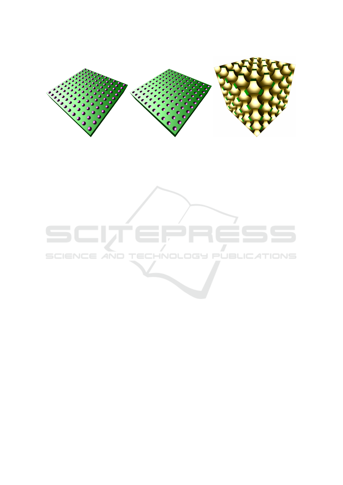
• Unions test model: Consists of a box with n
spheres placed on top of it (Figure 2a).
• Subtraction test model: Consists of a box with
n spheres placed on top of it which are reduced
from the supporting box (Figure 2b).
• Overlapping subtraction test model: The model
consists of a cubic box from which a cubic grid of
spheres is subtracted (Figure 2c).
The test system used for comparison has an Intel
Core i5-6400 CPU, one NVIDIA Geforce GTX 960,
and 16 GB of memory.
The rasterization-based and ray tracing based
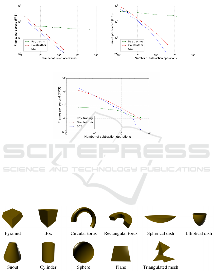
evaluation results are shown in figure 3. Figure 3a
shows the number of union operations and resulting
frames per second for rendering the union test case.
It shows that the rasterization-based rendering meth-
ods are faster for few number of primitives. However,
their performance vanishes with increasing number of
union operations. The ray tracing approach’s perfor-
mance is reducing with lower rate in comparison to
the rasterization-based approaches w.r.t. the number
of CSG operations. Furthermore, It can be seen that
the ray tracing approach keeps 40 frames per second
while rendering 1 million pixel-accurate spheres.
Figure 3b shows the rendering performance curve
(frames per second) of different rendering approaches
for models with different number of subtraction oper-
ations. Similar to the union test case, for a small num-
CSG Ray Tracing Revisited: Interactive Rendering of Massive Models Made of Non-planar Higher Order Primitives
261
(a) model made by union operations (b) model made by subtraction opera-
tions
(c) model made by overlapping subtrac-
tion operations
Figure 2: Evaluation of CSG models. Three CSG models were designed to compare the proposed CSG ray tracing approach
against (Goldfeather et al., 1986) and (Stewart et al., 2002) rasterization-based CSG rendering algorithms. The first model
(left figure) is the union of a number of spheres and a supporting box underneath. The second model (middle figure) is similar
to the first model but the spheres are subtracted from the supporting box. The last model (right figure) is constructed by
subtracting a 3d grid of spheres from a box. These cases are used to evaluate every aspect of CSG operations. The first one
is used to evaluate rendering of unions of primitives, the second one evaluates rendering of subtracted primitives, and the last
one is used to evaluate rendering of overlapping subtracted primitives. The evaluation results are shown in figure 3.
ber of subtractions the performance of rasterization-
based rendering approaches is higher than ray tracing.
Similarly it is abruptly dropping by increasing num-
ber of subtraction operations. A box with 200,000
holes inside can be ray traced approximately 20 times
per second.
Figure 3c shows the rendering performance for
the model made by subtracting different number of
overlapping holes. Since a lot of overlapping primi-
tives exist in this case, enabling hardware occlusion
query (Bittner et al., 2004) can have a significant im-
pact on the Goldfeather and SCS rendering modes be-
cause the primitives which do not contribute to the
final frame buffer will be removed from CSG render-
ing draw calls. Our measurements show that the oc-
clusion query improves the performance by factor of
2-10 for Goldfeather and 2-30 for SCS.
In this case ray tracing performance curve is
much lower than rasterization-based methods. On
our test machine ray tracing performance outperforms
the rasterization-based methods when more than 5
thousand CSG operations are performed. Although
number of frames per second is still larger than for
rasterization-based methods beyond 5k operations,
the absolute performance is not interactive anymore
(below 1 frames per second). The ray tracing per-
formance drops because a lot of subtracted primitives
are overlapping, the rays stop at every ray–primitive
intersection and a new ray is shot against the next sub-
tracted primitive. The acceleration structure has to be
traversed from root for every new ray shot which will
decreases the performance significantly.
4.2 Electric Circuit Model
A more practically relevant example, is an electric
circuit model consists of a number of stacked circuit
layers that are interconnected. In order to describe
the circuits, the model makes use of three different
primitives: extruded polygons, oriented boxes, and
cylinders (no triangles were used). Boxes are typi-
cally used for conductive circuit paths, while cylin-
ders model so-called vias, which connect circuit lay-
ers. Essentially, each model layer is an extruded 2D
design. This allows for storing the geometry data in a
very efficient way. For example, cylinders are always
oriented perpendicular to the layers, and only require
a center, vertical extrusion and radius as parameters.
Likewise, an extruded polygon is described by a set
of 2D points, plus its vertical position and extrusion
length. The extrusion vector is always perpendicular
to the 2D area.
Figure 5 shows two layers of the circuit model. It
can be seen how circular cutouts cut holes into an ex-
truded polygon. Conductive traces are formed with
boxes and cylinders. Since for all primitives the inter-
section with a ray is directly calculated, all curved sur-
faces are pixel-accurately displayed without the need
to use explicitly defined triangles.
For this scene we implemented all functions for
intersecting, shading, and traversal as custom pro-
grams in NVIDIA’s OptiX (Parker et al., 2010) frame-
work. The test scene shown in Figure 5 consists
of more than 88,000 primitives. On an NVIDIA
GeForce GTX 980 it can be rendered at more than
GRAPP 2017 - International Conference on Computer Graphics Theory and Applications
262
(a) Evaluation of union CSG operations (b) Evaluation of subtraction CSG operations
(c) Evaluation of overlapping subtraction CSG operations
Figure 3: Evaluation of CSG model rendering using different algorithms. The proposed ray tracing approach, and two
other rasterization-based CSG rendering methods (Goldfeather (Goldfeather et al., 1986) and SCS (Stewart et al., 2002))
are compared for rendering the models shown in Figure 2. Figure 3a evaluates the performance of rendering unions of
primitives. The performance of the rasterization-based rendering methods reduced significantly with increasing number of
CSG operations while the ray tracing approach performance is reducing slowly. The evaluation shows that the ray tracing
approach is well-fit to massive model rendering. Figure 3b evaluates the performance of primitive subtraction rendering. It
similarly shows that the ray tracing approach has significantly better performance for rendering a large number of subtracting
primitives. Figure 3c diagram evaluates rendering of CSG models having overlapping subtraction primitives. Calculating
pixel color covering a lot of overlapping subtracting primitives result in a lot of ray–primitive intersections which requires
traversing the ray tracer’s acceleration structure multiple times per pixel. Therefore the performance of the ray tracer drops
significantly while the impact on the stencil-buffer approaches is more moderate.
Figure 4: RVM primitives used in the plant model.
50 frames per second at full HD resolution. 4.3 Plant Model
This model (see Figure 1) was exported from the
AVEVA PDMS 3D CAD software, which is tailored
CSG Ray Tracing Revisited: Interactive Rendering of Massive Models Made of Non-planar Higher Order Primitives
263
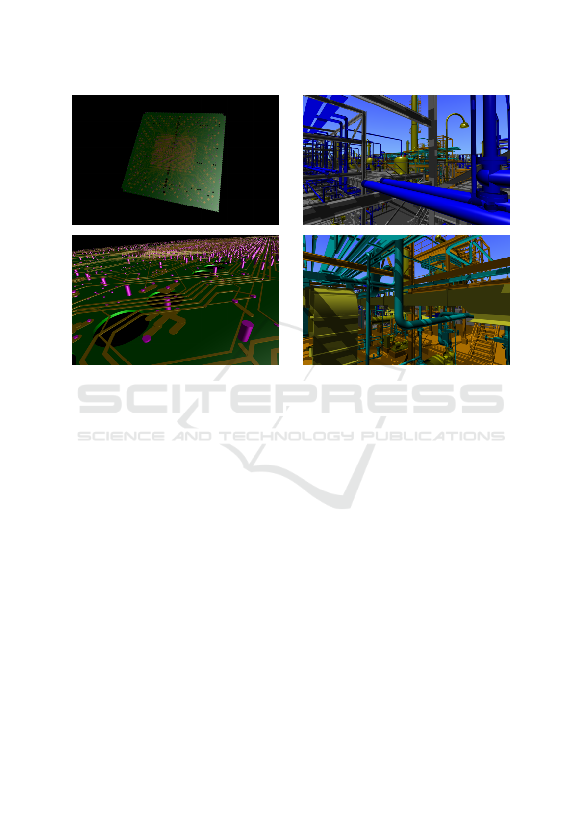
Figure 5: Two views of a Cell IC package. Top: Overview
of the layers. Bottom: Closeup view showing some cutouts.
Note the pixel-exact curved surfaces.
to the design of plant projects. The resulting data
is stored in RVM format (AVEVA, 2001). RVM de-
scribes geometry as a tree of named groups contain-
ing 11 types of primitives (including solids and pla-
nar primitives). Figure 4 shows the different RVM
primitives used to describe the plant model. In this
version of the model only positive primitives are in-
cluded, therefore only union operations need to be
performed, i.e., simply the closest ray intersection of
all primitives has to be determined.
The provided CAD data contains four different
plant datasets of varying size. As a stress test we
replicated them randomly 8,000 times. This resulted
in a scene consisting of more than 100,000,000 non-
planar primitives. Including acceleration structures
the whole scene amounts to more than 50 GB in
size. As this amount of data is too big to fit into
GPU memory, we ported our routines over to Intel’s
Embree (Wald et al., 2014) CPU ray tracing frame-
work. On a PC fitted with 64 GB of main memory and
two Intel Xeon E5-2650 v2 eight-core CPUs (clocked
at 2.60 GHz) the complete scene can be visualized at
10–20 frames per second including shadows.
Figure 6 presents two views illustrating the high
amount of detail found in the scene. Notice the intri-
cate structure of the pipes and tubes. Again, curved
Figure 6: Close up view of the plant model. The intri-
cate structure is modeled with the primitives described in
the AVEVA RVM CAD format.
surfaces appear pixel-exact.
5 CONCLUSIONS
In this paper, we demonstrated the application of real-
time ray tracing of massive CSG models made of
(higher-order) primitives using available state-of-the-
art ray tracing engines. This approach is of high prac-
tical relevance since in many scientific and engineer-
ing disciplines CAD models are designed which con-
sist of simple (solid or planar) primitives that can
be directly displayed by a ray tracer without hav-
ing to resort to triangulation. Apart from a straight-
forward implementation, real-time CSG ray tracing
has the advantage of on-the-fly compositing (with-
out any pre-processing), low storage requirements,
and pixel-accurate curved surfaces. Our results show
that our approach which is benefiting from today’s ad-
vanced rendering techniques has higher performance
for rendering massive CSG model compared to well-
known approaches e.g. Goldfeather (Goldfeather
et al., 1986) and SCS (Stewart et al., 2002). Addition-
ally, we applied our approach to two practical models:
PCB board, and factory which are made by CSG oper-
ations. We showed that 100 Mio of non-planar higher
GRAPP 2017 - International Conference on Computer Graphics Theory and Applications
264

order primitives (second-order and forth-order) can be
ray traced on 16 cores CPU at 10 frames per second.
ACKNOWLEDGEMENTS
The work of the authors has been supported by the
European Union’s Seventh Framework Programme
(FP7/2007-2013) under grant agreement no 619439.
REFERENCES
Abramowitz, M. (1974). Handbook of Mathematical Func-
tions, With Formulas, Graphs, and Mathematical Ta-
bles,. Dover Publications, Incorporated.
AVEVA (2001). PDMS DESIGN Reference
Manual Part 3: Elements and Attributes.
http://www.scribd.com/doc/23187647/Pdms-Design.
Bittner, J., Wimmer, M., Piringer, H., and Purgathofer, W.
(2004). Coherent hierarchical culling: Hardware oc-
clusion queries made useful. Computer Graphics Fo-
rum, 23(3):615–624.
Engel, W. (2014). GPU Pro 5: Advanced Rendering Tech-
niques. CRC Press.
Everitt, C. (2001). Interactive order-independent trans-
parency.
Gjonaj, E., Perotoni, M., and Weiland, T. (2006). Large
Scale Simulation of an Integrated Circuit Package.
In Proceedings of the 15th Conference on Electrical
Performance of Electronic Packaging (EPEP), pages
291–294.
Glassner, A. (1989). An Introduction to Ray Tracing. Mor-
gan Kaufmann.
Goldfeather, J., Hultquist, J. P., and Fuchs, H. (1986). Fast
Constructive-Solid Geometry Display in the Pixel-
Powers Graphics System. In Computer Graphics
(Proceedings of ACM SIGGRAPH), pages 107–116.
Guha, S., Krishnan, S., Munagala, K., and Venkatasubra-
manian, S. (2003). Application of the two-sided depth
test to csg rendering. In Proceedings of the 2003 Sym-
posium on Interactive 3D Graphics, I3D ’03, pages
177–180, New York, NY, USA. ACM.
Hable, J. and Rossignac, J. (2005). Blister: Gpu-based ren-
dering of boolean combinations of free-form triangu-
lated shapes. ACM Trans. Graph., 24(3):1024–1031.
Haeberli, P. and Akeley, K. (1990). The accumulation
buffer: Hardware support for high-quality rendering.
In Proceedings of the 17th Annual Conference on
Computer Graphics and Interactive Techniques, SIG-
GRAPH ’90, pages 309–318, New York, NY, USA.
ACM.
Hijazi, Y., Knoll, A., Schott, M., Kensler, A. E., Hansen,
C. D., and Hagen, H. (2010). CSG Operations of Ar-
bitrary Primitives with Interval Arithmetic and Real-
Time Ray Casting. In Scientific Visualization: Ad-
vanced Concepts, pages 78–89.
Kirsch, F. and D
¨
ollner, J. (2005). Opencsg: A library for
image-based csg rendering. In Proceedings of the An-
nual Conference on USENIX Annual Technical Con-
ference, ATEC ’05, pages 49–49, Berkeley, CA, USA.
USENIX Association.
MacDonald, D. J. and Booth, K. S. (1990). Heuristics for
ray tracing using space subdivision. Vis. Comput.,
6(3):153–166.
Parker, S. G., Bigler, J., Dietrich, A., Friedrich, H., Hobe-
rock, J., Luebke, D., McAllister, D., McGuire, M.,
Morley, K., Robison, A., and Stich, M. (2010). OptiX:
A General Purpose Ray Tracing Engine. In ACM
Transactions on Graphics (Proceedings of ACM SIG-
GRAPH), pages 66:1–66:13.
Romeiro, F., Velho, L., and de Figueiredo, L. H. (2006).
Hardware-assisted Rendering of CSG Models. In Pro-
ceedings of XIX Brazilian Symposium on Computer
Graphics and Image Processing (SIBGRAPI), pages
139–146.
Roth, S. D. (1982). Ray Casting for Modeling Solids. Com-
puter Graphics and Image Processing, 18(2):109–
144.
Stewart, N., Leach, G., and John, S. (2002). Linear-time
csg rendering of intersected convex objects. In In 10th
International Conference in Central Europe on Com-
puter Graphics, Visualization and Computer Vision -
WSCG 2002 (2002, pages 437–444.
Wald, I., Woop, S., Benthin, C., Johnson, G. S., and Ernst,
M. (2014). Embree: A Kernel Framework for Efficient
CPU Ray Tracing. In ACM Transactions on Graph-
ics (Proceedings of ACM SIGGRAPH), pages 143:1–
143:8.
Wiegand, T. E. (1996). Interactive rendering of csg models.
Computer Graphics Forum, 15(4):249–261.
CSG Ray Tracing Revisited: Interactive Rendering of Massive Models Made of Non-planar Higher Order Primitives
265
