
Fast Free Floor Detection for Range Cameras
Izaak Van Crombrugge
1
, Luc Mertens
1
and Rudi Penne
1,2
1
Faculty of Applied Engineering, University of Antwerp, Groenenborgerlaan 171, 2020 Antwerp, Belgium
2
Dept. of Mathematics, University of Antwerp, Middelheimlaan 1, 2020 Antwerp, Belgium
{izaak.vancrombrugge, luc.mertens, rudi.penne}@uantwerp.be
Keywords:
Planar Motion, Time-of-Flight Camera, RGB-D Camera, Free Floor Detection, Obstacle Detection, Ground
Plane Segmentation, Collision Avoidance.
Abstract:
A robust and fast free floor detection algorithm is indispensable in autonomous or assisted navigation as
it labels the drivable surface and marks obstacles. In this paper we propose a simple and fast method to
segment the free floor surface in range camera data by calculating the Euclidean distance between every
measured point of the point cloud and the ground plane. This method is accurate for planar motion, i.e. as
long as the camera stays at a fixed height and angle above the ground plane. This is most often the case in
driving mobile platforms in an indoor environment. Given this condition, the ground plane stays invariant
in camera coordinates. Obstacles as low as 40 mm are reliably detected. The detection works correct even
when ’multipath’ errors are present, a typical phenomenon of distance overestimation in corners when using
time-of-flight range cameras. To demonstrate the application of our segmentation method, we implemented it
to create a simple but accurate navigation map.
1 INTRODUCTION
When it comes to autonomous or assisted navigation,
obstacle detection is a key problem that needs to be
solved. For driving robots this corresponds directly
to detecting the free floor area, as all detections that
are not free floor must be labeled as obstacles. Given
the limited resources of mobile platforms, a fast and
robust method is preferred.
The success of existing floor detection methods
for single or multiple RGB camera systems (Li and
Birchfield, 2010; Aggarwal et al., 2014; Pears and
Liang, 2001; Liang and Pears, 2002; Lin and Song,
2015) is strongly dependent on visual clues. The tex-
ture, reflective properties and shading of the observed
scene have an important influence on the outcome.
To work reliably in a new environment, tweaking of
the parameters or new training has to be done. The
needed calculation time is also higher than 100 ms per
frame, which is too high for fast moving vehicles.
The usage of range cameras such as time-of-flight
cameras gives the possibility to use geometric infor-
mation, instead of relying on assumptions of the vi-
sual image. Often complex point cloud computations
are used to segment planes (Holz et al., 2011; Holz
et al., 2012; Poppinga et al., 2008; Schwarz et al.,
2011; Ye and Hegde, 2015; Pham et al., 2016; Qian
and Ye, 2014) like RANSAC plane fitting (Fischler
and Bolles, 1981; Torr and Zisserman, 2000) or re-
gion growing, resulting in slower than real-time pro-
cessing times. The method of (Penne et al., 2013) is
very fast, but does not segment the floor directly.
The aforementioned methods do not take advan-
tage of the assumption that the floor is at a fixed dis-
tance and angle from the sensor on the mobile plat-
form. In (Kircali and Tek, 2014) this prior knowledge
is used, resulting in a faster calculation. However,
their technique uses only a single threshold value. In
contrast, the technique we propose in this paper uses
two threshold values to cope with multipath errors
that occur in time-of-flight measurements. The pro-
posed method results in even faster calculations than
the one presented in (Kircali and Tek, 2014), has in-
tuitive parameters, and is algorithmically very sim-
ple, allowing for easy implementation on various plat-
forms.
2 CONDITIONS
The application of our technique is limited to planar
motion. The following conditions have to be met:
• The camera is mounted at a fixed height and angle
on the mobile platform.
Van Crombrugge I., Mertens L. and Penne R.
Fast Free Floor Detection for Range Cameras.
DOI: 10.5220/0006133505090516
In Proceedings of the 12th International Joint Conference on Computer Vision, Imaging and Computer Graphics Theory and Applications (VISIGRAPP 2017), pages 509-516
ISBN: 978-989-758-225-7
Copyright
c
2017 by SCITEPRESS – Science and Technology Publications, Lda. All rights reserved
509

• The floor plane is a flat surface.
• Translations are parallel to the floor plane.
• The axis of rotation is always perpendicular to the
floor plane.
3 PROCEDURE
The data flow is illustrated in Figure 1. The men-
tioned transformation matrix T is only needed to con-
struct the navigation map, which is not part of the
floor segmentation algorithm.
3.1 Calibration
First a calibration is done in a scene with enough con-
tinuous free floor surface. An area with valid floor
points is selected by hand and a plane is fitted through
the selected points using a least squares fit. The more
floor pixels are selected, the more reliable the fitted
plane will be. This step can also be automated us-
ing RANSAC plane fitting (Fischler and Bolles, 1981;
Torr and Zisserman, 2000). As this calibration is exe-
cuted only once for a given setup, it does not need to
run at real time speed.
The result of the calibration step is a floor plane π
given by the equation
π ↔ n
x
p
x
+ n
y
p
y
+ n
z
p
z
+ d = 0 (1)
where we choose the parameters so that (n
x
,n
y
,n
z
) =
~n the unit normal vector pointing towards the camera.
The pinhole center of the camera is the origin of
the used coordinate system, so the height h of the
camera above the floor can easily be found: h = −d.
This calculated height can then be compared to a
physical measurement of the height of the mounted
camera to confirm that the calibration is correct.
Note that when the camera motion is planar, the
plane equation is invariant in camera coordinates be-
cause nor the angle nor the distance of the camera to
the plane change.
3.1.1 Automatic Calibration
The knowledge that the ground plane is invariant for
planar motion can also be used to implement auto-
matic calibration. When moving around, the ground
plane can be detected as the one constant plane be-
cause – relative to the camera – most other planes will
be moving. The automatic calibration comprises of
the following steps:
1. Capture N image frames while moving.
2. From every frame, sample K points.
3. Merge the sampled points of all frames into one
point cloud.
4. Extract the largest plane in the point cloud using
a RANSAC plane fitting algorithm.
In practice, the point cloud would become too large
if all points of all frames would be used. N should
be chosen large enough so that there is enough move-
ment to filter out all non-ground planes. K is chosen
so that the point cloud has a practical size (= N · K
points) for the chosen RANSAC plane fitting algo-
rithm.
3.2 Distance Calculation
The calibration results in four scalars that determine
the floor plane: n
x
, n
y
, n
z
and d. Knowing that
k~nk = 1, the signed distance δ from any given point
P = (p
x
, p
y
, p
z
) to the floor plane π is
δ =
p
x
p
y
p
z
1
n
x
n
y
n
z
d
. (2)
As a result of the chosen normal direction: δ > 0
for points below the floor plane and δ < 0 for points
above the floor plane, such as the points of obstacles.
4 APPLICATION IN
TIME-OF-FLIGHT CAMERAS
Range cameras such as time-of-flight cameras usually
offer an organized point cloud in the form of X-, Y-
and Z-images. Given these images, for every pixel
the distance to the floor plane can be calculated. This
distance can then be compared to a threshold to mark
every pixel as being part of the floor plane or not.
4.1 Multipath Measurement Errors
A frequently occurring error in time-of-flight mea-
surements is the distance overestimation near corners
of even slightly reflective surfaces as the scattered
light is added to the direct measurement. This causes
some parts of the floor to be measured lower than the
actual floor plane. By using the signed distance, this
measurement error can be distinguished from distance
deviations caused by obstacles. Multipath deforma-
tions lie below the expected floor plane and have a
positive distance to the plane. Obstacles lie above the
plane and have a negative distance.
Two thresholds have to be defined, as shown in
Figure 2. The first one for the maximum distance
VISAPP 2017 - International Conference on Computer Vision Theory and Applications
510
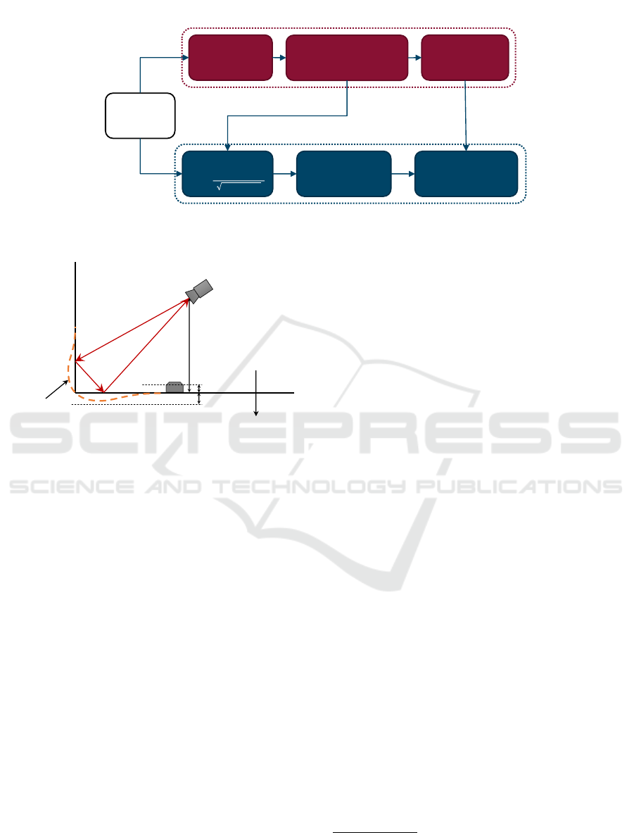
ToF camera
RANSAC plane
detection
Calibration parameters
Transformation
matrix
Calibration
Distance image
Segmented image
Navigation map:
projected on floor
Realtime floor detection
Figure 1: The data flow consists of two main parts: offline calibration and real time floor detection.
wall
floor
ToF camera
distance
overestimation
threshold 1
threshold 2
0
𝛿
h
Figure 2: Time-of-flight cameras tend to overestimate the
distance near corners due to the multiple paths the reflected
light can take.
above the floor plane. This threshold has to be larger
than the maximum expected noise and smaller than
the minimum size of obstacles that have to be de-
tected. The second threshold limits the allowable dis-
tance below the floor plane. It has to be larger than
the maximum expected overestimation due to multi-
path reflections and smaller than the depth of e.g. de-
scending stairs or steps.
4.2 Computing Time and Memory Cost
For every pixel, only three multiplications, three ad-
ditions and one or two comparisons are needed, so
the calculation time behaves linearly. This makes the
technique suitable for newer range cameras with ever
increasing image resolutions without having to sub-
sample. The simple computation is especially suitable
for mobile robots with limited computational power.
The needed memory is also linear. For every pixel
only four variables are stored: the measured coordi-
nates x, y, and z and the resulting Boolean stating if
the pixel is part of the free floor or not. The stored
calibration data consists of only four scalar parame-
ters
1
(n
x
, n
y
, n
z
, and d in equation 1) representing the
plane.
4.2.1 Advantages
• Scalable with higher resolution cameras given the
linear time and memory requirements.
• Scalable with multiple cameras on one platform.
• Suitable for low cost, low power, and low weight
mobile platforms.
• High speed computation allows for faster move-
ment and navigation.
• Multiple floor models could be tested to compen-
sate for small camera rotations caused by the flex-
ing of the camera mounting.
5 MEASUREMENTS
To validate our method, we did three experiments:
• A practical test with a Kinect time-of-flight cam-
era mounted on a wheelchair. The resulting seg-
mentation and generated floor map in Figure 5 are
meant for visual evaluation.
• Simulations to quantify the effect of camera roll
on the obtained accuracy.
• A numerical comparison with (Kircali and Tek,
2014), where we apply our method on the same
dataset and compare this with their results.
1
Only three parameters are linear independent, but we
chose to save all four parameters to simplify the computa-
tions and interpretations.
Fast Free Floor Detection for Range Cameras
511
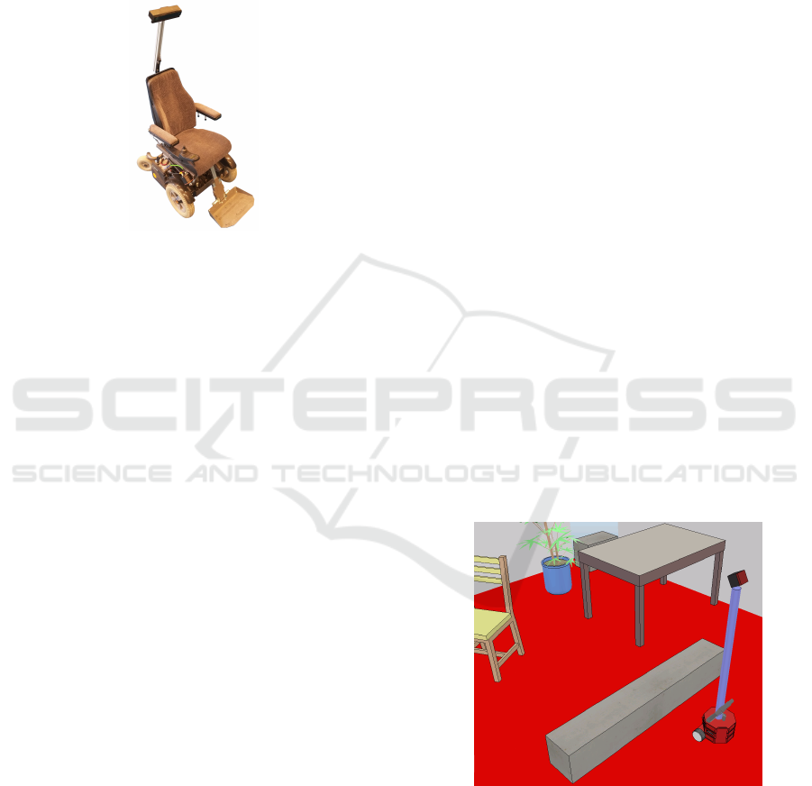
5.1 Experimental Setup
In the first experiment we mounted a Microsoft Kinect
for Xbox One time-of-flight sensor on an electric
wheelchair. As shown in Figure 3, the camera was
placed at a height of 1600 mm and at an angle of 20
◦
with respect to the ground plane.
Figure 3: The experimental setup consists of a Kinect time-
of-flight camera mounted on an electric wheelchair.
We used a first threshold of 40 mm above the floor
plane to be large enough to prevent false positives
caused by noise and low enough to detect common
obstacles and non-drivable surfaces. A second thresh-
old of 100 mm below the floor was chosen to account
for the multipath measurement errors.
After calculating the distance from every pixel to
the ground plane, a 3 by 3 median filter or a 5 by 5
Gaussian filter is applied to filter out measurement
noise. The result of this filtering is thresholded. The
pixels with an invalid measurement get a distance of
’Not-a-Number’. Thus for every pixel the segmenta-
tion results in one of three possible states: part of the
floor, obstacle or no information.
5.2 Results
The processing was done in Matlab on an Intel Core
i7-4810MQ processor (2.8 GHz quad-core). In Ta-
ble 1 the timings of the different parts of the algorithm
are shown. The duration of the described method is
only the detection time. The projection and map cre-
ation are optional steps and are not part of the seg-
mentation. The used Gaussian blur filter had a ker-
nel with standard deviation σ = 5 and a filter size of
5 by 5. Due to the large σ relative to the filter size,
this filter acts like an approximation of an averaging
filter. The results shown in Figure 5 were obtained
using this Gaussian blur filter.
To demonstrate the output of our floor detection,
the results are overlaid on the luminance image of the
time-of-flight camera in red and green. We also cre-
ated a navigation map by projecting the world points
on the floor plane using transformation matrix T (see
Figure 1). Every bin in the navigation map scales to a
5 cm by 5 cm square in world space. The more detec-
tions are projected in a square, the brighter the green
or red color will be.
The results give a reliable segmentation with no
false detections of free floor. On rare occasions part of
the free floor is detected as an obstacle. This happens
when the wheelchair accelerates abruptly, causing the
camera mounting to flex a bit. When the acceleration
ends, the false negatives disappear. This can easily be
solved by using a stiffer mounting and is not a failing
of the method.
5.2.1 Note
The presented results were obtained using Matlab
which has a relatively large computational overhead.
When using lower level programming languages to
implement this algorithm, the needed calculation time
could be further reduced.
5.3 Simulation Results
As long as the camera roll and tilt variation is neg-
ligible, the condition of planar motion is assumed to
be met and the floor segmentation is accurate. Using
a manually created ground truth is impractical, as the
accuracy of the manual segmentation would be lower
than that of the algorithm. To be able to do a numeri-
cal evaluation of the accuracy we used a simulation in
V-REP (Rohmer et al., 2013).
Figure 4: Simulated scene for numerical evaluation of the
accuracy.
A time-of-flight camera was mounted on a robot
at a height of 1151 mm and tilted downwards 30
◦
as
shown in Figure 4. The camera has the same focal
length and resolution as the Kinect used in the exper-
iments. An RGB camera is placed at the exact same
position and orientation as the range camera, which is
VISAPP 2017 - International Conference on Computer Vision Theory and Applications
512
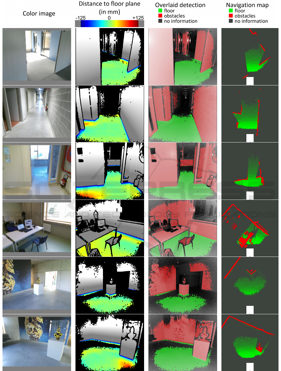
Figure 5: Measurement result in various scenes. In the navigation map the position of the wheelchair is shown as a white
rectangle and the camera position as a small black dot at the bottom of the map.
Fast Free Floor Detection for Range Cameras
513
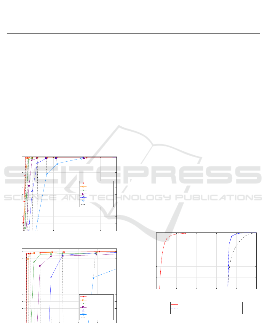
Table 1: Timing of the algorithm averaged over 810 frames in 6 different scenes. All times are in milliseconds.
Detection [ms] Selection & projection [ms] Map creation [ms] Total [ms]
Without filter 0.73 8.21 8.56 17.50
With 5 × 5 Gaussian filter 2.54 6.38 6.76 15.68
With 3 × 3 median filter 12.13 7.46 7.13 26.72
only possible in simulation. The floor is colored red
so that the ground truth can be determined based on
the RGB-image.
The calibration was done when the camera had no
roll. To see the effect of camera roll on our meth-
ods accuracy, the same simulation was repeated with
camera roll angles of 1
◦
to 10
◦
compared to the cal-
ibration orientation. Figure 6 shows the increase in
false positives when the camera roll angle increases.
The results are plotted in ”Receiver Operating
Characteristic” curves. They show the quality of a bi-
nary classifier by plotting the true positive rate against
the false positive rate. We also plotted the accuracy,
the ratio between the number of correctly segmented
pixels and the total number of valid pixels.
0 0.05 0.1 0.15 0.2 0.25 0.3
False ground detection rate
0.5
0.55
0.6
0.65
0.7
0.75
0.8
0.85
0.9
0.95
1
True ground detection rate
Free Floor ROC (Simulation) Overview
100
150
200
300
0° angle error
1° angle error
2° angle error
3° angle error
5° angle error
10° angle error
150 Threshold in mm
0 0.05 0.1 0.15 0.2 0.25
False ground detection rate
0.99
0.991
0.992
0.993
0.994
0.995
0.996
0.997
0.998
0.999
1
True ground detection rate
Free Floor ROC (Simulation) Zoomed in
30
40
50
70
100
150
200
300
0° angle error
1° angle error
2° angle error
3° angle error
5° angle error
10° angle error
150 Threshold in mm
Figure 6: Receiver Operating Characteristic curves for our
floor detection algorithm on a simulation dataset for thresh-
olds between 10 mm and 300 mm. Two zoom levels are
shown for clarity.
The mean accuracy of the 300 simulated frames
shown in Figure 8 was 0.992 with a threshold height
of 30 mm. They were obtained with 0
◦
roll error.
The spikes with lower accuracy are caused where the
frames of the RGB camera and the range camera were
not correctly synchronised, so that the detection was
compared with the ground truth of the previous or
next frame.
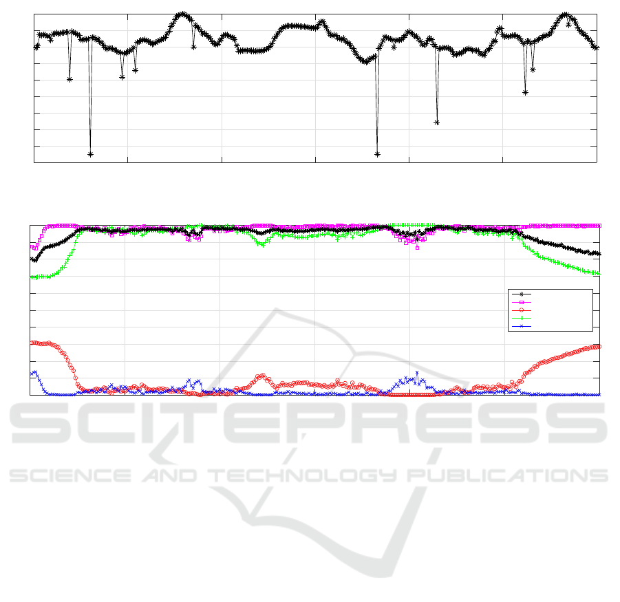
5.4 Numerical Comparison
Using one of the datasets used in (Kircali and Tek,
2014), a comparison of the accuracy between both
methods can be made. Although the platform used
to capture this dataset does not satisfy the condition of
planar motion as it has too much roll and tilt, the accu-
racy obtained using our method is surprisingly good
compared to the results of (Kircali and Tek, 2014).
The excessive roll and tilt is notable in Figure 9 in
the first 25 and last 40 frames. Still, the mean accu-
racy over all 300 frames is 0.951 using our method,
while their mean accuracy was around 0.85. This dif-
ference can be explained by the relatively high rate
of false positive ground detections produced by their
method. Their false positive rate was higher than 0.35
while the ROC curves in Figure 7 shows much lower
false positive rates for our method.
0 0.1 0.2 0.3 0.4 0.5
False ground detection rate
0.5
0.6
0.7
0.8
0.9
1
True ground detection rate
Free Floor ROC
Our method
Fixed pitch method of Kircali and Tek, 2014
Pitch compensated method of Kircali and Tek, 2014
Figure 7: Receiver Operating Characteristic curves for our
proposed method applied on the dataset of (Kircali and Tek,
2014) for thresholds between 5 mm and 150 mm, and their
results on the same dataset.
VISAPP 2017 - International Conference on Computer Vision Theory and Applications
514
0 50 100 150 200 250 300
Frame number
0.955
0.96
0.965
0.97
0.975
0.98
0.985
0.99
0.995
1
Simulation Accuracy per Frame
Figure 8: Accuracy results in a simulation with no roll error of 300 frames.
0 50 100 150 200 250 300
Frame number
0
0.1
0.2
0.3
0.4
0.5
0.6
0.7
0.8
0.9
1
Accuracy per frame
total Accuracy
true positive floor
false positive floor
true positive obstacles
false positive obstacles
Figure 9: Accuracy results for our proposed method applied on the dataset of (Kircali and Tek, 2014). For every frame the
True Positive Rate, False Positive Rate and total Accuracy was calculated. The effect of excessive roll and tilt is notable in
the first 25 and last 40 frames.
6 CONCLUSIONS
We have proposed a very simple method to differenti-
ate between free floor surfaces and obstacles for mo-
bile platforms that use planar motion. The segmen-
tation step itself takes less than 1 ms without filtering
and less than 3 ms with a 5 by 5 Gaussian blur fil-
ter, staying well within the time restrictions of real
time obstacle avoidance. The calculation time can be
further reduced by implementing the algorithm in a
lower level programming language as the current re-
sults are obtained using Matlab.
When compared to a state of art floor detection
method for range cameras, the results of our algo-
rithm show a significantly higher accuracy. This ac-
curacy is even higher when the measurement is made
with a stiffer platform satisfying the planar motion
condition, such as the used wheelchair. Beside the
numeric evaluation, the accurate segmentation can
clearly be seen in the images with the segmentation
overlay (third column in Figure 5). A movie with the
results can be found on our website: op3mech.be.
ACKNOWLEDGEMENTS
This research was made possible by the Smart Data
Clouds project, a TETRA project funded by VLAIO
(Flanders Innovation & Entrepreneurship).
REFERENCES
Aggarwal, S., Namboodiri, A. M., and Jawahar, C. V.
(2014). Estimating Floor Regions in Cluttered In-
door Scenes from First Person Camera View. In 2014
22nd International Conference on Pattern Recogni-
tion (ICPR), pages 4275–4280.
Fischler, M. A. and Bolles, R. C. (1981). Random sample
consensus: a paradigm for model fitting with appli-
cations to image analysis and automated cartography.
Communications of the ACM, 24(6):381–395.
Holz, D., Holzer, S., Rusu, R. B., and Behnke, S. (2012).
Real-Time Plane Segmentation Using RGB-D Cam-
eras, pages 306–317. Springer Berlin Heidelberg.
Holz, D., Schnabel, R., Droeschel, D., St
¨
uckler, J., and
Behnke, S. (2011). Towards Semantic Scene Anal-
Fast Free Floor Detection for Range Cameras
515

ysis with Time-of-Flight Cameras, pages 121–132.
Springer Berlin Heidelberg, Berlin, Heidelberg.
Kircali, D. and Tek, F. B. (2014). Ground Plane Detection
Using an RGB-D Sensor. In Information Sciences and
Systems 2014, pages 69–77.
Li, Y. and Birchfield, S. T. (2010). Image-Based Segmen-
tation of Indoor Corridor Floors for a Mobile Robot.
In IEEE/RSJ 2010 International Conference on Intel-
ligent Robots and Systems (IROS 2010), pages 837–
843.
Liang, B. and Pears, N. (2002). Ground plane segmentation
from multiple visual cues. In Second Internation Con-
ference on Image and Graphics, Pts 1 and 2, volume
4875 of Proceedings of the Society of Photo-Optical
Instrumentation Engineers (SPIE), pages 822–829.
Lin, C.-H. and Song, K.-T. (2015). Robust ground plane re-
gion detection using multiple visual cues for obstacle
avoidance of a mobile robot. ROBOTICA, 33(2):436–
450.
Pears, N. and Liang, B. (2001). Ground plane segmenta-
tion for mobile robot visual navigation. In IROS 2001:
Proceedings of the 2001 IEEE/RJS International Con-
ference on Intelligent Robots and Systems, Vols 1-4:
Expanding the Societal Role of Robotics in the Next
Millennium, pages 1513–1518.
Penne, R., Mertens, L., and Ribbens, B. (2013). Planar Seg-
mentation by Time-of-Flight Cameras. In Advanced
Concepts for Intelligent Vision Systems, ACIVS 2013,
volume 8192 of Lecture Notes in Computer Science,
pages 286–297.
Pham, H.-H., Le, T.-L., and Vuillerme, N. (2016). Real-
Time Obstacle Detection System in Indoor Envi-
ronment for the Visually Impaired Using Microsoft
Kinect Sensor. Journal of Sensors.
Poppinga, J., Vaskevicius, N., Birk, A., and Pathak, K.
(2008). Fast Plane Detection and Polygonalization in
Noisy 3D Range Images. In 2008 IEEE/RSJ Interna-
tional Conference on Robots and Intelligent Systems,
Vols 1-3, Conference Proceedings, pages 3378–3383.
Qian, X. and Ye, C. (2014). NCC-RANSAC: A Fast Plane
Extraction Method for 3-D Range Data Segmentation.
IEEE Transactions on Cybernetics, 44(12):2771–
2783.
Rohmer, E., Singh, S. P., and Freese, M. (2013). V-rep:
A versatile and scalable robot simulation framework.
In 2013 IEEE/RSJ International Conference on Intel-
ligent Robots and Systems, pages 1321–1326. IEEE.
Schwarz, L. A., Mateus, D., Lallemand, J., and Navab, N.
(2011). Tracking planes with time of flight cameras
and j-linkage. In Applications of Computer Vision
(WACV), 2011 IEEE Workshop on, pages 664–671.
Torr, P. H. and Zisserman, A. (2000). Mlesac: A new ro-
bust estimator with application to estimating image
geometry. Computer Vision and Image Understand-
ing, 78(1):138–156.
Ye, C. and Hegde, G. M. (2015). Plane Segmentation of 3D
Time-of-Flight Camera’s Range Data by Normalized
Cuts for Navigating a Tracked Robot. International
Journal of Intelligent Control and Systems, 20(1):9–
15.
VISAPP 2017 - International Conference on Computer Vision Theory and Applications
516
