
Integrating Interface Modeling and Analysis in an Industrial Setting
Ivan Kurtev
1
, Mathijs Schuts
2
, Jozef Hooman
3
and Dirk-Jan Swagerman
2
1
Altran, Eindhoven, The Netherlands
2
Philips, Best, The Netherlands
3
TNO-ESI & Radboud University, Eindhoven, The Netherlands
Keywords:
Interface Modeling, Interface Analysis, Component Verification, Component Monitoring, Model-based
Engineering.
Abstract:
Precise specification of system component interfaces enables analysis of component behavior and checking of
conformance of an implementation to the interface specification. Very often component interfaces are only de-
fined by their signature and without a formal description of the admissible behavior and timing assumptions.
In this paper we present a framework named ComMA (Component Modeling and Analysis) that supports
model-based engineering (MBE) of high-tech systems by formalizing interface specifications. ComMA pro-
vides a family of domain-specific languages that integrate existing techniques from formal behavioral and time
modeling and is easily extensible. It contains tools that support different phases of the development process
and can be integrated in the industrial way of working. The framework is applied in the context of the family
of interventional X-ray machines developed by Philips.
1 INTRODUCTION
Modern high-tech systems are complex artefacts that
support many usage scenarios and system configura-
tions. They integrate a large number of software and
hardware components often provided by third party
suppliers. Precise specification of the interfaces of
these components is vital for a successful system in-
tegration.
Problem Statement
Typically an interface lists its methods (commands)
and notifications (events) that form an interface sig-
nature and is sometimes accompanied by an indi-
cation of allowed interactions. Timing expectations
for replying to a command, periodicity of events
and others usually stay implicit. This concerns both
internal interfaces (between own developed compo-
nents) and external interfaces with third party com-
ponents. Problems may occur during integration and
after changes in component upgrades. For example,
an external supplier may deliver a new version of a
component with improved hardware or software and
implicitly changed time behavior. This might lead to a
difficult to detect, unexpected, and erroneous system
behavior.
Companies often use certain standards for trans-
parent deployment of interfaces, such as COM or
company-specific solutions, but the interface defini-
tions themselves are usually only specified in a docu-
ment in natural text and informal diagrams. The infor-
mal and potentially imprecise interface specifications
make it difficult to guarantee that software implemen-
tations conform to their specification.
Goal
The goal of our work is to support model-based en-
gineering (MBE) of high-tech systems in a way that
avoids the aforementioned problems by formalizing
interface specifications. Besides a definition of the
signature, an interface description should also include
a specification of the allowed behavior, i.e., which se-
quences of method calls and notifications are allowed,
and the timing constraints.
Furthermore, the aim is to provide practical tool
support for handling interfaces throughout the devel-
opment process: from the early phases of interface
definition to the implementation, testing and mainte-
nance of interfaces. For instance, during the initial
interface specification phase, visualization and simu-
lation are often useful to detect issues early in the pro-
cess. Later, the automatic generation of implementa-
Kurtev I., Schuts M., Hooman J. and Swagerman D.
Integrating Interface Modeling and Analysis in an Industrial Setting.
DOI: 10.5220/0006133103450352
In Proceedings of the 5th International Conference on Model-Driven Engineering and Software Development (MODELSWARD 2017), pages 345-352
ISBN: 978-989-758-210-3
Copyright
c
2017 by SCITEPRESS – Science and Technology Publications, Lda. All rights reserved
345

tion artefacts speeds up the development. During the
testing and maintenance phases it is important to be
able to check conformance to interface specifications
after upgrades of components. This is especially rele-
vant for upgrades of third party components.
Finally, a major concern is the ability of the tools
to be easily integrated in the industrial workflow. This
means that they can deal with the existing standard(s)
for component deployment, can support a large and
heterogeneous group of industrial users and, hence,
have to be prepared for frequent change requests.
In this paper we focus on high-tech systems in the
medical domain. The industrial context is the fam-
ily of interventional X-ray machines developed by
Philips.
Approach and Contribution
We developed a framework named ComMA (Compo-
nent Modeling and Analysis) that contains a family
of Domain-Specific Languages (DSLs) (van Deursen
and Klint, 1998) and supporting tools. In addition to
the interface signature, engineers can define the inter-
face behavior in a state machine-based DSL. Timing
constraints are defined as relations between commu-
nication events decorated with the admissible time in-
tervals. The most important analysis tool allows mon-
itoring and checking of component executions against
interface specifications. The monitoring can be per-
formed for already existing traces or by monitoring
executions at runtime. Model transformations serve
as bridges to other analysis and visualization tools.
ComMA supports several phases in the develop-
ment process. During the initial phase of interface
specification, engineers can obtain an executable rep-
resentation in order to simulate and validate the com-
ponent behavior model and get confidence whether it
captures their intention. Document generation is par-
tially supported in combination with the generation of
visual representations of some model aspects. An im-
plementation of company-specific interface proxies is
obtained by code generation. Component monitoring
is used during testing and maintenance phases.
The DSL for interface specification combines con-
cepts available in approaches for behavioral and time
modeling. These approaches usually use dedicated
(and often formal) languages and tools. Our approach
provides an integrated solution based on a single spec-
ification language that is extensible, reflects the needs
of engineers and can be incorporated in the indus-
trial way of working. The DSLs in ComMA are
not buisness-specific and therefore can be regarded as
horizontal DSLs. Business-specific functionality (in
the context of Philips) is present in some of the trans-
formation tools, for example, code generators that re-
flect the company best practices and infrastructure.
Paper Outline
We first position our work with regards to tools and
techniques with similar purpose (Section 2). An
overview of the DSLs and the available support for
different development phases is presented in Sec-
tion 3. ComMA DSLs are illustrated in the context
of an industrial case. The case study is about mod-
eling the power control unit of interventional X-ray
machines developed by Philips (Section 4). The be-
havioral specification language and runtime monitor-
ing support are explained in Section 5 and Section 6
respectively. The paper concludes with a discussion
and future work considerations.
2 RELATED WORK
The need for interface specifications has been ad-
dressed in a number of academic and industrial ini-
tiatives. Verum ASD (G.H. Broadfoot, 2005) and
its successor Dezyne are toolsets for component in-
terface modeling and design. The available tools sup-
port checking of conformance between an interface
and its design, checking for deadlocks and livelocks
and property-preserving code generation. Both ASD
and Dezyne use model checking under the hood and
shield the engineers from intricacies of formal tech-
niques. Dezyne uses a DSL tailored to facilitate the
supported model checking tasks. This comes with the
price of limitations, for example, data passed to the
interface methods cannot be read and changed. Spec-
ification of time behavior is not supported.
Unified Modeling Language (UML) and its profile
for systems modeling SysML allow component inter-
face specification and modeling of implementation.
Marte is a UML profile for modeling real-time sys-
tems that allows specification of timing constraints.
Several commercial tools such as IBM Rhapsody and
Enterprise Architect among others support execution
of UML models. Analysis of UML and SysML mod-
els requires dedicated tools and a choice of a suitable
formalization of the language semantics (Kim et al.,
2013). Engineers usually need only a subset of the ex-
pressive power of these rich languages. Furthermore,
UML often needs tailoring for a given problem area
via profiles which is in effect a domain-specific ex-
tension to the language.
Runtime verification (Falcone et al., 2013) is a
technique for monitoring the behavior of software
MODELSWARD 2017 - 5th International Conference on Model-Driven Engineering and Software Development
346
during its execution and checking if the behavior con-
forms to a specification. Existing approaches use
specifications based on grammars, automata, code an-
notations and rules. In the presented work we were in-
spired by the rule systems for runtime verification Ea-
gle and RuleR (Barringer et al., 2007). Our monitor-
ing tool uses state machines expressed in the ComMA
DSL for interface specification and interprets them
as a set of runtime monitoring rules. The monitor-
ing algorithm uses the main ideas in the algorithm of
RuleR.
Several formal languages exist for specification of
temporal properties of systems. It is generally dif-
ficult for the practitioners to specify temporal logic
formulas against a formal representation of the system
under development. The timing fragment of our DSL
is inspired by Metric Temporal Logic (MTL) (Ouak-
nine and Worrell, 2008), an extension to Linear Tem-
poral Logic (LTL). Engineers can specify timing
properties in terms of the commands and events de-
fined in the interface signature. We do not use the full
expressive power of MTL but limit ourselves to the
commonly found practical scenarios.
Timing constraints can also be expressed as a
timed automaton in Uppaal (Behrmann et al., 2004).
This approach was applied in one of the earlier ver-
sions of our DSL for interface behavior where time
variables and constraints were used. The feedback
from the engineers indicated a preference for a differ-
ent style for specifying timing constraints. This moti-
vated our choice for the MTL-based approach.
There are several general and industry-specific
initiatives for interface definition languages. Franca
is an initiative originated from an automotive industry
consortium
1
. Similarly to Franca, ComMA provides
a language for interface signatures and state-based be-
havior with additional support for timing constraints
and analysis features.
3 OVERVIEW OF COMMA
The ComMA framework provides three main DSLs
to be used by engineers.
• DSL for interface signatures. Engineers can de-
fine the signatures of interfaces as groups of com-
mands and notifications.
• DSL for interface behavior. The behavior is de-
fined as state machines accompanied by timing
rules.
• DSL for capturing execution traces. The format
of traces is independent from a particular commu-
1
http://franca.github.io/franca/
nication protocol. Engineers are not expected to
use this DSL directly. Execution traces are usu-
ally automatically generated from sources such as
execution logs or captured network traffic.
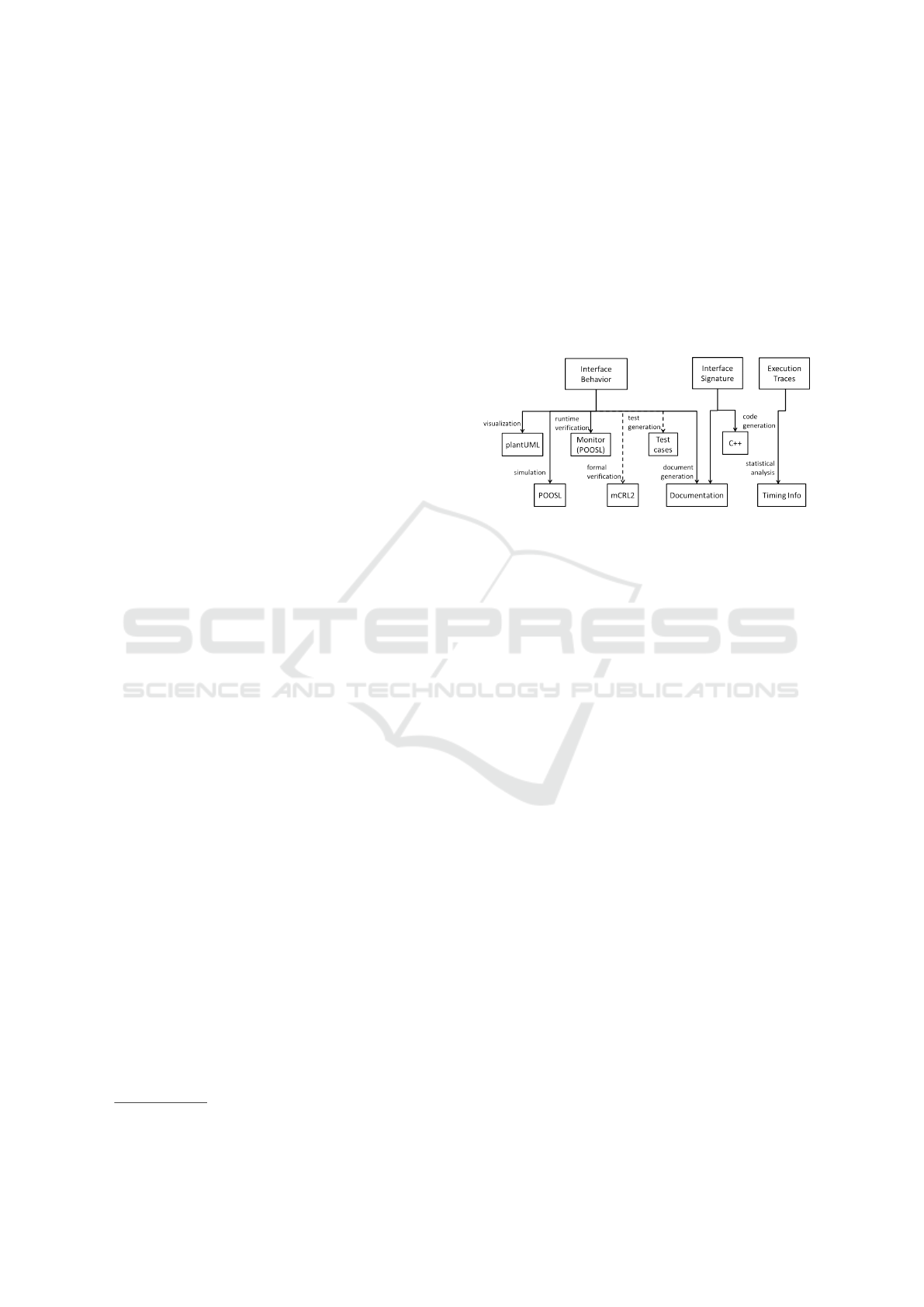
ComMA supports different phases in the develop-
ment process. Starting from a single model which
contains behavior specification or interface signature,
different artifacts can be obtained via model transfor-
mations. An overview of this support is given in Fig.
1. Arrows represent model transformations and the
label indicates the supported task.
Figure 1: Overview of ComMA languages and available
tool support.
• Visualization. A graphical overview of state ma-
chines is often useful. ComMA provides gener-
ation of plantUML files that can be rendered as
state machines. In addition to that, all timing rules
can be intuitively represented as annotated UML
sequence diagrams.
• Simulation. Simulation of a model helps in re-
ceiving an early feedback and detecting errors.
State machine models are transformed to POOSL
programs (Parallel Object Oriented Specification
Language) (Theelen et al., 2007). Engineers can
use the POOSL environment that has a step-by-
step execution facility with visual support.
• Runtime monitoring. A modified version of the
transformation to POOSL produces an executable
monitor for runtime verification. This feature is
explained in details in Section 6.
• Formal verification and model-based testing. The
transformations to formal verification and model-
based testing frameworks are given as dashed
lines because they are not fully implemented for
the behavior specification DSL. We have a prior
experience with a similar DSL for which gener-
ators to mCRL2 models (Groote and Mousavi,
2014) and model-based testing specifications
were developed and applied.
• Code generation. Interface signatures can be
transformed to C++ code that is a declaration
of the interface before its deployment on the
company-specific platform.
Integrating Interface Modeling and Analysis in an Industrial Setting
347

• Document generation. The GenDoc document
generation framework
2
is used to extract com-
ments from models and insert them in a document
template. This process also utilizes the diagrams
obtained from state machines and timing rules.
• Statistical Analysis. Models of execution traces
are used for statistical analysis of time informa-
tion. The times for execution of interface com-
mands are extracted to a separate file suitable for
statistical processing.
• Reverse engineering. Interface behavior of al-
ready existing components can be automatically
derived by using model learning techniques. The
derived models are then manually augmented and
timing constraints are added. Some of the aspects
of this reverse engineering process are still an on-
going work.
ComMA DSLs provide a textual syntax defined in
Xtext (Bettini, 2013). Code editors with syntax high-
lighting, static analysis and code completion are au-
tomatically generated by the Xtext framework. The
DSLs were developed in a close collaboration with
their intended users. After the initial design, a series
of short increments as response to feature requests
were executed.
4 INDUSTRIAL APPLICATION
Our work is motivated by the needs in the develop-
ment of interventional X-ray machines of the com-
pany Philips. These machines have a complex dis-
tributed architecture with many software and hard-
ware components. In this paper we use the power
control unit as an example component. This unit is
responsible for powering the hardware components.
In case of a power failure it uses a Uninterruptable
Power Supply (UPS). If the UPS is exhausted the sys-
tem is automatically shutdown. The unit has 3 main
interfaces: a user interface with On and Off buttons
and light indicators, a physical power supply inter-
face, and a software control interface. In this paper we
focus on the software interfaces. They allow polling
the system about the status of startup and shutdown
scenarios. The unit sends notifications on changes in
the status of the system. The interfaces also allow ex-
ecution of testing scenarios in which stimuli are sent
to simulate the main events such as On/Off button is
pressed, power has failed, etc.
ComMA is applied in several phases in the devel-
opment. The interface signatures, behavior and tim-
ing rules are expressed in the corresponding DSLs.
2
https://www.eclipse.org/gendoc/
The timing properties of interest are the allowed time
to execute certain commands, the time for complet-
ing a scenario for startup/shutdown, and the periods
of recurrence of certain events. For example, once the
unit is on UPS source it shall send periodic notifica-
tions about the energy level of the UPS. Philips uses a
company-specific component middleware. ComMA
is used for automatic generation of interface prox-
ies. At the time of testing and integration, the runtime
monitoring tool checks if the component implementa-
tion adheres to the behavioral specification and timing
requirements.
The following sections elaborate how ComMA
was applied in the relevant steps in the development
process.
5 LANGUAGE FOR SPECIFYING
COMPONENT INTERFACES
ComMA provides a simple DSL for defining interface
signatures. Simplified versions of two interfaces are
given: ISuSd for Startup/Shutdown and ITest.
interface ISuSd {
Types:
enum State { S y stemOn S y s t e mOff }
enum Ups S t a t e { OnMains O n Batter y }
commands
State GetState
notifications
Stat e U p date ( State )
Ups S t ate U p d ate ( UpsState )
}
The definition of the interface signature is
straightforward. We distinguish between commands
that may be called synchronously and asynchronous
notifications sent to the clients. Users can define enu-
merations, record types and collection types.
It should be noted that ISuSd does not provide
commands for the actual startup and shutdown of the
system. The user does this via the On and Off but-
tons. For testing purposes the On and Off stimuli can
be sent via the ITest interface.
interface ITest {
Types:
enum Sti m u l u s {
Sys t e mOn B u t ton Syst e m O ffB u t ton
...
}
enum State {
SystemOn Syst e m Of f T ra n s it i o ni n g
MODELSWARD 2017 - 5th International Conference on Model-Driven Engineering and Software Development
348

Syste m O f f Sys t e m Off E r r or
Sy s t em O n Tra n s it i o ni n g
}
commands
bool Injec t S t im u l u s ( Stimulus )
State GetState
notifications
Sta t e U p date ( State )
}
Command InjectStimulus simulates an event that
may happen during the operation of the unit. It returns
true if the component can initiate a testing scenario
and false otherwise.
The command GetState returns the current state
of the unit. It is more informative than the similar
command defined in ISuSd interface. The startup and
shutdown procedures take time, hence the system en-
ters transitioning states before the completion of the
procedure.
Another DSL part of ComMA allows interface be-
havior specifications. The behavior of one or more
interfaces is given in several state machines. A state
machine is associated with at least one interface. In
terms of the DSL we say that a machine ’provides’
interfaces. The calls to commands in the provided in-
terfaces can be used as triggers in the state transitions.
The DSL allows only flat machines, that is, nested
states are forbidden. The machines are completely or-
thogonal, they do not share variables and have disjoint
sets of transition triggers. All state transitions must
be observable: either a transition is triggered by a call
or the transition effect is observable, for example, by
sending a notification.
The following listing shows a part of the model of
the interface behavior. Some transitions are omitted.
machine P o w e rCo n t r o l
provides ISuSd ITest {
Variables:
UpsState u p s S tate
init:
upsState := O n M a i n s
initial state S y s t e m O ff {
transition
trigger: ISuS d :: G e t S t a t e do:
reply( I S u S d :: State :: SystemOff )
next state: SystemO f f
transition
trigger: Inj e c t Sti m u l us ( Stimulus s)
guard: ( s == Sys t e m On B u t ton ) do:
ITest :: S tate U p d a te (
Sy s t em O n Tra n s it i o ni n g
)
reply( t rue )
next state: Sy s t em O n Tra n s it i o ni n g
// Other tra n s i t ions
}
state S y st e m O nT r a ns i t io n i ng {
mandatory transition do:
ITest :: S tate U p d a te ( SystemOn )
next state: SystemOn
// Other tra n s i t ions
}
state Sys t e m O n { . . . }
state S y st e m Of f T ra n s i t i o n in g {...}
state S y s tem O f f Err o r {...}
}
The states in the machine PowerControl corre-
spond to the possible states defined in the ITest in-
terface. Transitions can be triggered by calls to inter-
face commands and can be guarded. Reception of a
call for which there is no transition defined in a given
state or all guards are false is treated as an error.
Transition bodies contain actions which are as-
signments to variables, if-then-else branching and
sending output events. Transitions may happen also
without a trigger. A transition may be indicated as
mandatory meaning that it must happen at some point
while the machine is in the given state. Static checks
are implemented for mutually exclusive mandatory
transitions, for example, the ones that leave the cur-
rent state and always prevent the enactement of other
mandatory transitions. A mandatory transition is
shown in state SystemOnTransitioning. It reflects the
fact that the system will always complete the startup
procedure and will send a notification before moving
to SystemOn.
The language supports non-determinism in two
ways. First, it is possible to give more than one target
state for a transition. The second form concerns un-
known values in notifications and replies. The value
is given as ’*’ symbol.
The behavior specification DSL allows the defini-
tion of time constraints in the form of rules. These
rules give the admissible intervals between events in
different contexts. There are four rule types.
re q u e st S t ate I S uSd
call ISuSd :: G etState
-[ .. 15. 0 ms] - > reply
The interval rule constrains the allowed interval
between two events. The example rule named re-
questStateISuSd establishes that the time for replying
to the GetState command is no more than 15 ms.
Integrating Interface Modeling and Analysis in an Industrial Setting
349
The second rule type is called conditional inter-
val. It states that if both events are observed then
the interval between them is not exceeding the spec-
ified interval. This rule is suitable in case of non-
deterministic transitions when an event may have al-
ternative follow-ups.
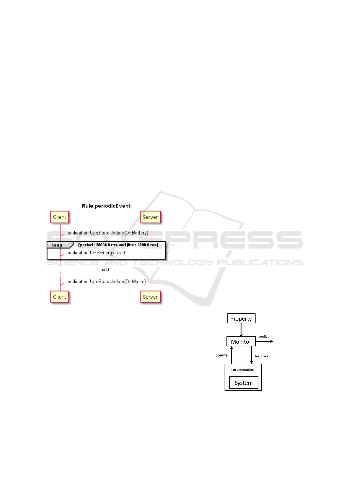
The third rule type allows specifications of peri-
odic events. The following rule states that notification
on UPS level is given every two minutes.
notification U p s Sta t e U pda t e ( O n B a t t ery )
then
notification U P S Ene r g y Lev e l
with period 12 0 0 0 0 . 0 ms
jitter 2000.0 ms
until
notification U p s Sta t e U pda t e ( OnMai n s )
The periodic event will not be observed once the
system is back on mains power (until clause).
The visual representation of a periodic event rule
is shown in Fig. 2.
Figure 2: Diagrammatic representation of a periodic time
rule as a sequence diagram.
The last rule type allows specification of timed
scenarios.
group S t a rtU p S cen a r io
call I n j ect S t i mul u s ( S y s tem O n But t o n )
and
reply( t rue )
-> [ .. 1 5.0 ms ] between events
-[ .. 1000.0 ms ]- >
notification
ISuSd :: S tate U p d a te (
ISuSd :: S tate :: SystemO n
)
end group
A startup scenario consists of injecting the stimu-
lus SystemOnButton followed by a reply with value
true and a notification. The notification should be ob-
served not later than 1 second after the reply.
6 COMPONENT MONITORING
The runtime monitoring support of ComMA was mo-
tivated by the need to extend the current Philips test
infrastructure. At the time of component integration,
system functions are extensively tested. The experi-
ence at Philips shows that issues discovered at system
level are often traced back to issues related to the con-
formance of components (possibly supplied by a third
party) to their interface specifications. Many issues of
this kind are manifested during the interaction of sev-
eral components and it is difficult to detect them if
a component is tested in isolation. Monitoring and
checking component interactions can reveal the prob-
lems at an earlier phase and help in analyzing logs
harvested from systems in the field.
The relation between runtime verification and test-
ing is already described in the literature (Leucker and
Schallhart, 2009). Runtime verification shares com-
monalities with testing based on oracles. In our con-
text, the interface behavior specification can be used
to check if the component responses are correct, that
is, the oracles used in testing are derived from the
model.
General Scheme for Component
Monitoring
Generally, runtime verification is a technique for
checking system behavior against a property during
the execution of the system. The general scheme (Fal-
cone et al., 2013) is given in Fig. 3.
Figure 3: General scheme of runtime verification.
The property may be given in a formal specifica-
tion language (automata, logic formula, grammar), as
a set of rules or a program. A monitor is derived
MODELSWARD 2017 - 5th International Conference on Model-Driven Engineering and Software Development
350

from a set of properties. The task of the monitor is
to observe the execution of the system and to produce
a verdict: a statement if the observation satisfies the
properties. The observation may be a series of system
states or a series of input and output events. Moni-
toring is executed either step by step along with the
system execution or over a log that contains the ob-
servations.
This general approach is applied as follows. The
system is a component that implements a set of inter-
faces. Behavior specification of the interfaces (state
machines and timing rules) plays the role of proper-
ties. Monitoring is done after the execution is com-
plete and the observations are available. An observa-
tion is a timed sequence of the commands sent to the
component and the system responses.
The monitor is a POOSL program that is synthe-
sized from the state machine models and the timing
rules. It receives the commands in the execution trace,
compares them to outputs from the model and pro-
duces the verdict. Verdicts can be errors and warn-
ings. Errors are violations of the state machine logic.
Warnings are violations of time rules. Detection of an
error stops the monitoring process, after a warning the
monitoring continues.
The process of component monitoring is inte-
grated in the development workflow at Philips. The
monitoring framework is available as a chain of com-
mand line tools that work together with the test infras-
tructure. Currently, test scripts produce the execution
sequences to be monitored.
In the following subsections we elaborate on the
mechanisms for capturing the observations, the im-
plementation of monitors, and error reporting. We
also report on the results of applying component mon-
itoring on the power control unit.
Capturing Observations
The component monitoring implemented in ComMA
does not require instrumentation of the checked com-
ponents. Very often they are third party compo-
nents and the implementation is not directly acces-
sible. Furthermore, the components do not always
produce suitable execution logs. In the presented in-
dustrial application, the components are available via
a distributed platform developed in-house at Philips.
The communication protocol is implemented on top
of the HTTP protocol. In order to obtain an execution
trace, the network traffic is sniffed and the relevant
communication events are filtered.
Observations captured by monitoring the network
need reordering before they are sent to the moni-
tor. Several commands can be sent concurrently from
multiple clients. These commands are queued at the
component side and executed sequentially. Our mon-
itoring algorithm reorders the events into a sequence
of pairs of a command and a reply.
Currently component monitoring is applied offline
after the execution trace is complete but we do not
perceive serious conceptual obstacles to execute it at
runtime.
Implementation of Monitor
The transitions defined in the state machines and the
timing rules are interpreted as monitor rules in a way
similar to the rules used in RuleR. The monitoring
algorithm is adapted accordingly.
A transition in a given state and with a given
trigger is treated as a rule for which the trigger and
transition guard are the precondition. The enactment
of the transition produces a set of expected observa-
tions: output events in the body of the transition. If
the rule is non-deterministic then several sets of ex-
pected observations are produced. The observations
received from the system are compared with the sets
of expected observations and inconsistent sets are re-
moved. Inconsistent sets are those with expected ob-
servations that differ from the real observations. If
no consistent set is present at a certain execution step
then the system behavior violates the specification. If
in a given state a command is received for which there
is no transition or all guards of the relevant transitions
are false then an error is raised.
Transitions without a trigger are interpreted as fol-
lows. When the model enters a given state all such
transitions with a guard that is true are potentially ap-
plicable. In order to simplify the monitoring algo-
rithm the behavior specifications are restricted. Tran-
sitions without triggers can produce only a single
notification. If the system emits a notification, the
monitor is asked if this notification can be produced.
Mandatory transitions that are not fired lead to errors.
Checking of timing rules uses time stamps of
events produced by the network sniffing tool. Ev-
ery timing rule is transformed to an automaton that
consumes timestamped events. The automaton is ac-
tivated if a triggering event is consumed. During
the monitoring a set of activated rules is maintained.
When the next event is consumed the activated rules
may produce a verdict or stay active. Other rules may
be activated in turn.
All errors and warnings are reported in textual and
diagrammatic way. Diagrams are UML sequence dia-
grams with the context of the problem and the differ-
ence between the expected and the observed behavior.
Integrating Interface Modeling and Analysis in an Industrial Setting
351

Application of Component Monitoring on
the Power Control Unit
Component monitoring was applied on the power
control unit provided by a supplier and several issues
were found. For instance, duplicated notifications on
state changes in a situation where a single notifica-
tion is expected and missing notifications when the
system goes on UPS source. Statistical analysis was
also applied on execution traces. The time intervals
for completing the executions of a given command
were collected and plotted in a diagram. The actual
distribution shape showed two peaks whereas a single
peak was expected. Further investigation revealed the
implementation decisions that were the cause of this
effect.
The described issues were missed in system level
tests. Component monitoring of behavior including
time improved the testing process.
7 CONCLUSIONS
The need for precise component interface specifica-
tions is longstanding in the industry and has drawn
attention of the research community. We presented
ComMA, a framework for interface behavior specifi-
cation with a rich tool support for different develop-
ment phases. The DSLs in ComMA integrate tech-
niques and results from different research areas and
provide a single entry point for engineers to specify
and develop component interfaces.
We did not employ the full expressive power of
the used formal languages. Instead, DSL constructs
are selected on the basis of the concrete needs of the
engineers and optimized for solving their most recur-
ring problems. Our experience in applying the DSLs
shows that this approach is crucial for the tool and lan-
guage adoption along with pragmatical aspects like
stable editors, ergonomic concrete syntax and visual-
ization. Whenever necessary, capabilities of special-
ized analysis tools can be used by building bridges in
the form of model transformations.
In general, ComMA was successfully applied on
the power control unit and fulfilled the tasks that were
the initial motivation of the framework. The applica-
tion of the techniques to several other components at
Philips is an ongoing work. This will provide further
validation insights.
The developed languages are not business-specific
and are not restricted to the medical domain. They are
aimed at problems that are found in other domains as
well and utilize general techniques thus making the
framework easily generalizable.
Future work intentions include extending the
toolset with transformations to model-based testing
and model checking facilities. Further experimenta-
tion with model learning aims at extending and im-
proving the interface behavior extraction from exist-
ing components.
REFERENCES
Barringer, H., Rydeheard, D. E., and Havelund, K. (2007).
Rule systems for run-time monitoring: From Eagle to
RuleR. In Sokolsky, O. and Tasiran, S., editors, Run-
time Verification, RV 2007, volume 4839 of Lecture
Notes in Computer Science, pages 111–125. Springer.
Behrmann, G., David, A., and Larsen, K. G. (2004). A
tutorial on Uppaal. In Bernardo, M. and Corradini, F.,
editors, Formal Methods for the Design of Real-Time
Systems, volume 3185 of Lecture Notes in Computer
Science, pages 200–236. Springer.
Bettini, L. (2013). Implementing Domain-Specific Lan-
guages with Xtext and Xtend. Packt Publishing Ltd.
Falcone, Y., Havelund, K., and Reger, G. (2013). A tutorial
on runtime verification. In Broy, M., Peled, D. A., and
Kalus, G., editors, Engineering Dependable Software
Systems, volume 34 of NATO Science for Peace and
Security Series, D: Information and Communication
Security, pages 141–175. IOS Press.
Groote, J. F. and Mousavi, M. R. (2014). Modeling and
Analysis of Communicating Systems. MIT Press.
Kim, H., Fried, D., Menegay, P., Soremekun, G., and Os-
ter, C. (2013). Application of integrated modeling and
analysis to development of complex systems. Proce-
dia Computer Science, 16:98 – 107.
Leucker, M. and Schallhart, C. (2009). A brief account of
runtime verification. The Journal of Logic and Alge-
braic Programming, 78(5):293 – 303.
Ouaknine, J. and Worrell, J. (2008). Some recent results in
metric temporal logic. In Cassez, F. and Jard, C., edi-
tors, Formal Modeling and Analysis of Timed Systems,
6th International Conference, FORMATS 2008, Saint
Malo, France, September 15-17, 2008. Proceedings,
volume 5215 of Lecture Notes in Computer Science,
pages 1–13. Springer.
G.H. Broadfoot (2005). ASD case notes: Costs and ben-
efits of applying formal methods to industrial control
software. In Fitzgerald, J., Hayes, I., and Tarlecki, A.,
editors, FM 2005: Formal Methods, LNCS, vol. 3582,
pages 548–551. Springer, Heidelberg.
Theelen, B. D., Florescu, O., Geilen, M., Huang, J., van der
Putten, P., and Voeten, J. (2007). Software/Hardware
Engineering with the Parallel Object-Oriented Specifi-
cation Language. In Proc. of MEMOCODE’07, pages
139–148. IEEE.
van Deursen, A. and Klint, P. (1998). Little languages: lit-
tle maintenance? Journal of Software Maintenance,
10(2):75–92.
MODELSWARD 2017 - 5th International Conference on Model-Driven Engineering and Software Development
352
