
Automating the Customization of Model-Driven Software
Engineering Environments
César Cuevas Cuesta, Patricia López Martínez and José M. Drake
Group of Software Engineering and Real-Time, University of Cantabria, Santander, Spain
Keywords: MDE, Meta-modelling, Development Environments, Process Engineering.
Abstract: This paper presents a strategy to facilitate the customization of MDSE software development environments,
which aims at providing the software engineers who design, implement and maintain those environments
with capacity to automate the generation of tools supporting new development processes. A generic
conception for the design of software development environments based on the MDSE paradigm, called
MDDE (Model-Driven Development Environment), has been defined as basis of the proposed strategy. In
MDDE, the definition of the processes that determine the functionality of an environment as well as their
options regarding interaction, supervision and control by the users are completely formulated as models. To
support this capability, the MDDE reference model includes a meta-model that formalizes such models. A
sample implementation called MDDE-MinMAST2 is presented for illustrative purposes.
1 INTRODUCTION
Model-Driven Software Engineering (MDSE)
(Schmidt, 2006) is nowadays considered one of the
most appropriate paradigms for coping with the
increasing complexity inherent to software
development. MDSE environments deal with a wide
variety of aspects of the software being developed,
providing uniform support for the basic management
processes (creation, verification, transformation,
persistence, etc.) involved in software development.
However, their usability is sometimes far from
efficient, because they can also include more
sophisticated tools. Software development processes
are typically complex, repetitive, and most of all,
dependent on the customs of the companies. Hence,
the domain-specific engineers who use the
environments may not find them friendly because
the processes they require are not easily supported.
Adapting the environments to the specific needs of a
company or domain is not an easy task, since the
engineers responsible for their development usually
experience a conflict that represents an important
drawback for the adoption of any new software
discipline (not only MDSE): If they do not want to
frequently ask for assistance to those experts in the
infrastructure of the platform on which the
environment is built atop (e.g. in an MDSE context,
experts in EMF), they must become experts on it
themselves. This necessity clashes with their
common reluctance to work outside their fields or to
use new technologies, such as MDSE. Indeed, they
would prefer to make use of well-known tools that
allow them to work in their fields in an isolated
manner. Therefore, the adequate strategy to
encourage the acceptance of a software discipline
cannot be to expect that the environment designers
will become experts in its associated technologies.
Instead, from our viewpoint, the efforts must target
the development of strategies and facilities for the
environment designers to become autonomous, by
means of a light adoption of the new discipline,
MDSE in this case.
Thus, under this philosophy, we present MDDE
(Model-Driven Development Environment), a
generic conception for the design of MDSE
environments. Its purpose is to foster the adoption
and consolidation of MDSE by those engineers
responsible for the design/customization of new
environments for their corresponding domain-
specific methodologies. This is achieved by
simplifying the way in which the designer adds to
the environment support for new development
processes or tools. Being an MDSE approach,
adding a new development process will consist on
its formulation as a model. This model will be later
interpreted by an internal tool provided by the
environment, which will generate all the resources
Cuevas Cuesta C., Løspez Martà nez P. and M. Drake J.
Automating the Customization of Model-Driven Software Engineering Environments.
DOI: 10.5220/0006130903370344
In Proceedings of the 5th International Conference on Model-Driven Engineering and Software Development (MODELSWARD 2017), pages 337-344
ISBN: 978-989-758-210-3
Copyright
c
2017 by SCITEPRESS – Science and Technology Publications, Lda. All rights reserved
337

required for the execution and control of the process.
The main component of MDDE is its reference
model. It defines the basic functional and
interactional capabilities that are common to any
MDDE environment. It provides the developer of
software systems with the information he needs for
working with any MDDE environment and the
designer of environments with the base architecture
that rules the design of new environments or the
customization of existing ones.
The rest of the paper is structured as follows.
Section 2 presents an overview of the MDDE
conception and reference model. Section 3 analyses
the possibilities that MDDE provides for designing
environments while Section 4 presents a sample
MDDE environment. Finally, Section 5 and 6 expose
some related work and conclusions, respectively.
2 MDDE OVERVIEW AND
REFERENCE MODEL
2.1 MDDE Operational Foundations
The operational approach on which MDDE is based
considers that the end users utilize the environments
by means of the supervised execution of processes.
These processes consist of the sequential or iterative
execution of more basic operations, called tasks,
which are primitive operations implemented by code
in the environment. According to MDSE, the
processes are defined as models that describe,
among other things, the sequence of constituent
tasks. The tasks are also defined as models, which
describe their nature, the models on which they
operate, their involved model transformations and
the information provided to the user to take
decisions and to control, supervise, validate or
orchestrate their execution.
Hence, the design and specification of processes
in an MDDE environment basically means to
formulate models and not to write code. In order to
support this capability, the reference model includes
a meta-model (presented in subsection 2.2) that
formalizes the models of processes and types of
tasks. Any MDDE environment includes a native
tool that interprets these models, allowing the
supervised execution of the processes.
2.2 MDDE Reference Model
The reference model can be seen from three
different viewpoints:
The structural view addresses the constituent
conceptual elements, the relations among them
and their formulation as a meta-model.
The functional view defines the elements that
form the internal engine of the environment and
the interfaces that it uses.
The implementation view. Although the reference
model is agnostic from the underlying MDSE
platform, a specific implementation is required to
validate it. This is orthogonal to the domain or
methodology to which the environment is
oriented. For instance, we may have a sample
MDDE environment implemented on
Eclipse/EMF and oriented to the design of RTS
using a given methodology such as MAST
(González Harbour et al. 2001). This
environment would be called MDDE-
Eclipse/EMF-MAST.
This paper focuses on the structural aspects, which
are explained in the rest of the section, although a
proof of concept MDDE environment
implementation is presented in section 4. Due to
space limitations, the exposition of the functional
view is omitted, but a deep study about it can be
found in (Cuevas, 2016), including a study of the
suitability of Eclipse as supporting platform.
2.2.1 Conceptual Elements
Models. The information managed in an MDDE
environment is formulated as models compliant to
meta-models that are part of the environment. Three
types of models can be distinguished according to
their function:
Tool Models, which describe the operability,
configuration and status of the tools (processes)
provided by the environment.
Domain Models, which contain information
about some aspect of the system under
development (SUD).
Interaction Models, which formulate information
exchanged between the user and the
environment.
An orthogonal classification can be done according
to the model lifecycle:
Native Models, included in the environment
since its creation and hence, delivered with it.
They are typically tool models.
Project Models, with information relevant to the
specific SUD. They are typically domain models.
Temporal Models, created to manage internal
information during a development process.
The set of native models together with the rest of
native elements (e.g. model transformations, sets of
MODELSWARD 2017 - 5th International Conference on Model-Driven Engineering and Software Development
338

constraints, etc.) constitute the basis of the
functional and evolutional capabilities of an MDDE
environment. Due to their nature, these models
cannot be modified or eliminated. In contrast,
project models can be produced manually by the
user or generated by the invocation of an
environment process. In any case, they are always
persisted in the environment data space.
MDDE Tools (mTool). An mTool is a high-level
process provided by an MDDE environment to assist
the user in incorporating information about the SUD
into the environment or presenting the SUD
information according to its own viewpoint.
Moreover, the user can process the information by
applying transformation, integration or analysis
techniques provided by the mTools. An mTool is
invoked explicitly by the user and it is composed of
a sequence of lower level, elementary activities
(tasks), defined individually to allow reutilization in
different mTools.
Each mTool is formulated as a model, so that
incorporating the tool to the environment only
requires to register such model. Some mTools are
native, i.e. their models are registered in the
environment during its creation and stay unaffected
during the whole environment lifecycle. On the
other hand, the environment designer can define new
mTools, either by providing their descriptive models
or by modifying the models of already existing ones.
The model of an mTool describes its:
Functionality, i.e. the set of tasks it includes.
Invocation context, i.e. the environment element
on which the mTool can be invoked, either
directly (menu or button) or by contextual
selection.
Configuration options, defined as a sub-model
that specifies the identifiers, types and default
values of the configuration parameters.
Status information, which will be generated
during the tool execution. This execution status
is also described as a sub-model which is
fulfilled according to the results obtained during
the execution. This sub-model provides
information about the success/failure of the
execution of each internal task and the models
generated during the execution of the mTool.
The execution of an mTool is always controlled and
supervised by the user. After invocation, there are at
least three points in which the user intervention is
required: 1) setting or accepting the launch
configuration; 2) launching the execution; and 3)
setting the execution as finished, which involves
eliminating all the status information and temporal
models. When these are the only interaction points
between the user and the mTool, the execution is
said to be performed in the continuous mode,
whereas in the step-by-step mode the execution
requires the user to take part in the launch of every
individual internal task. As will be explained later in
this section, to facilitate the management of an
mTool execution, upon tool invocation the
environment deploys an interaction frame
with all
the required controls. This frame is automatically
populated according to the mTool descriptive model,
showing the sequence of constituent tasks along with
their corresponding configuration parameters.
MDDE Tasks (mTask). The basic operative element
of the MDDE reference model is the mTask. An
mTask represents any useful operation in the
management of the SUD or the environment itself.
The mTasks are the elementary activities that form
the mTools included in the environment. This
element is introduced due to different reasons:
To enable the reutilization of operations shared
among different mTools.
To enable the execution of artefacts developed
outside the environment.
To provide an homogeneous management
interface that eases the composition of activities
in the processes and the interaction with the
environment resources.
An mTask can be atomic or interactive. An atomic
mTask is executed without user intervention, since
the data required for the execution comes from the
initial configuration of its container mTool. On the
other hand, an interactive mTask requires user
intervention either for managing the information
used by the task or for deciding among different
control flow options. According to how the mTasks
implement their functionality, an orthogonal
categorization distinguishes between mTasks that
implement conventional MDSE operations and
mTasks that adapt artefacts (see next paragraph).
MDDE Artefacts (mGadgets). They are software
resources (code) used by the mTools during their
execution but that have been developed outside the
environment, independently of the MDDE reference
model. Their usage by an mTool as well as their
interaction with the environment resources are not
performed directly, but an adapter is required for
their invocation, configuration and interaction.
An mGadget can be internal (executed in the
environment memory space, where it is invoked) or
external (executed in other memory space, either in
same processor or in a different one – external or
remote mGadget). The management of the external
mGadgets and their interaction with the environment
are supported by a set of communication
Automating the Customization of Model-Driven Software Engineering Environments
339
mechanisms defined in the framework and provided
by the platform on which the environment executes.
Likewise, the invocation requires an application
aimed at launching mGadgets (called
mGadgetLauncher) to be run on the same memory
space as the mGadget.
The distinction between internal/external gadgets
implies a parallel distinction between their
corresponding adapter mTasks. The ones that adapt
an internal mGadget provide the input models
required by the mGadget, properly formatted, store
the output models created by the mGadget and
transmit the control and status messages between the
gadget and the environment. However, the
adaptation of an external gadget requires the
intervention of the underlying communication
service of the platform and the serialization of the
input/output models and the messages interchanged
among the adapter task and the mGadget.
Information not Formulated as Models. The
external scope of an MDDE environment is typically
heterogeneous, which sometimes makes impossible
to keep all the information formulated as models
compliant to meta-models known by the
environment. Therefore, MDDE has been designed
to support information formulated by means of
textual languages, which facilitates the interchange
of information with other environments/systems that
have their own specific language. It is also useful for
granting persistence when the information lifecycle
is longer than the environment`s. As an example, an
MDDE environment can provide capability for
importing or exporting XML textual information,
formalized by means of W3C-Schema templates, or
specific textual languages formalized with Xtext
(Eysholdt and Behrens, 2016).
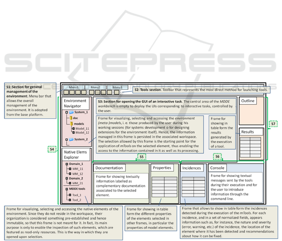
MDDE Workbench. This is the reference GUI that
must be implemented by any MDDE environment.
Figure 1 sketches the basic workbench design,
formed by a set of interaction frames, graphical
zones with viewers and controls that implement the
interaction mechanism with the user. The Elements
Management section (S4) includes two explorer-like
frames which allow the access to all the information
(model, meta-models, etc.) of the environment. The
Elements Information section (S5) exposes the
information relative to the selected individual
elements. The Processes Execution section (S6)
exposes information about the execution of the
mTools. Finally, the Processes Management section
(S7) lets the user control the execution of an invoked
mTool, set values for the configuration parameters,
supervise the execution status and finish or abort the
execution. Figure 2 details the Tool Outline frame,
which shows the constitution of an mTool (sequence
of mTasks) and allows to control its execution.
Figure 1: MDDE workbench outline.
MODELSWARD 2017 - 5th International Conference on Model-Driven Engineering and Software Development
340
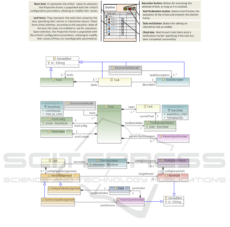
Figure 2: Interaction elements within the Tool outline frame.
Figure 3: Core of the MDDE meta-model.
Figure 4: Class Tool.
Figure 5: Definition and assignment of parameters.
2.2.2 MDDE Meta-Model
The MDDE meta-model formalizes the structural
aspects of the MDDE reference model. An MDDE
environment can be specified as a set of models
compliant to it. These models are the ones that
formulate the mTools available in the environment
(which in turn encapsulate the models of their
mTasks), the models of the mTaskTypes included in
the environment and the models that represent the
environments themselves, although the latter only
plays a role of container of the rest of models. An
mTaskType is a parameterized entity (and hence,
configurable) whose specific realization (assignment
of values to the configuration parameters) leads to a
specific mTask. Hence, the mTasks contained in the
model of an mTool are just realizations of the
mTaskTypes defined in the environment.
Figure 3 shows the core of the MDDE meta-
model.
TaskDescriptor
represents the concept of
mTaskType.
Task
represents the concept of mTask,
as specific realization of an mTaskType instance,
referenced through the
descriptor
reference.
Tool
represents the concept of mTool. The set of mTasks
that form the mTool are defined through the
tasks
association, all of them instances of
Task
. Finally,
EnvironmnentModel
represents the concept of
environment. Its instances reference the set of
mTools and mTaskTypes that form the specification
of the MDDE environment through its
tools
and
taskDescriptors
associations. Figure 4 and Figure
5 extend the exposition of the meta-model. The
Automating the Customization of Model-Driven Software Engineering Environments
341
detailed definition of each class is omitted here due
to space reasons. The complete meta-model
specification, along with its Ecore formulation, can
be found in http://www.istr.unican.es/members/
cesarcuevas/phd/es/mdde.html.
3 MDDE ENVIRONMENTS
DESIGN
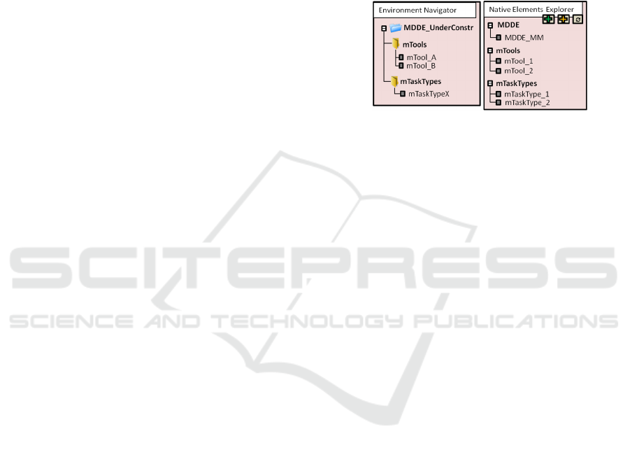
When oriented to an environment designer, the
layout of the MDDE workbench simplifies the
general version exposed in Section 2.2.1. It gets rid
of the Outline, Results and Console frames and the
contents of the Environment Navigator and Native
Elements Explorer are modified (see Figure 6). The
designer is now interested in the mTaskTypes
defined in the environment, which he can use to
define new mTools. Moreover, he can also design
new mTaskTypes. Now, the Environment Navigator
shows only a simple structure of containers in which
the designer can store his new defined mTools and
mTaskTypes, whereas the Native Elements Explorer
shows the MDDE meta-model and the native
mTaskTypes defined within the environment.
Furthermore, this last frame provides now controls
for adding new mTools or new mTaskTypes.
Creation of New mTools and mTaskTypes. An
MDDE environment provides the NewTool/
NewTaskType wizards which can be invoked from
the Add mTool/mTaskType buttons, respectively.
Upon invocation the corresponding mTool/
mTaskType model is created, with its
Tool/
TaskDescriptor
root container element properly
initialized. In the case of an mTool, the
Tool
instance contains two
Task
instances. The first one,
mTask_1, serves as template so it is not assigned to
any descriptor (it must be completed later); whereas
the second one, called Termination, corresponds to
the Process Finish type. Then, the generated model
is persisted in the
MDDE_UnderConstr
directory and
it is opened in the edition area for the user to
complete its construction.
Registration of New mTools and mTaskTypes.
Completing the model of a new mTool or
mTaskType may take several work sessions, so these
temporal models are persisted in the workspace but
they are not considered available MDDE assets.
When the new element is completely defined, it
must be explicitly added to the environment. With
that aim, two functionalities (Register mTool/
mTaskType) have been defined. The registration
process implies a preliminary phase of verification
(compliance to the MDDE meta-model and
constraints fulfilment). Once verified, the model
moves from its provisional location in the workspace
to the location established for the MDDE assets,
disappearing from the Environment Navigator frame
and appearing in the Native Elements Explorer one.
From that moment, the asset is available to be used
either in the design of systems (in the case of
mTools) or new mTools (in the case of mTaskTypes).
Figure 6: The frames Environment Navigator and
Explorer of native elements for environments design.
4 MDDE-MinMAST2
This section introduces MDDE-MinMAST2 as an
example of an MDDE environment. Its purpose is to
support the analysis and design of RTS according to
the MAST methodology. Again, due to space
reasons, the example is not completely exposed here.
Its complete specification, along with the Ecore
models that constitute its implementation on
Eclipse/EMF (MDDE-Eclipse/EMF-MinMAST2)
can be found in http://www.istr.unican.es/members/
cesarcuevas/phd/es/mdde.html.
4.1 MAST Overview
MAST (Modelling and Analysis Suite for Real-Time
Applications) (González Harbour et al., 2016) is a
suite for the design and analysis of RTS, developed
by the ISTR Group of the University of Cantabria. It
comprises both a methodology for modelling the
temporal behaviour of RTS and a set of tools that
operate on those models by applying different kinds
of analyses (schedulability analysis, scheduling
parameters assignment, simulation, etc.).
The modelling methodology is formulated by
means of three meta-models. The main one is the
MAST meta-model – currently in its evolution to
MAST-2 (Cuevas et al., 2012) –, used for modelling
real-time behaviour. The MASTResults meta-model
for modelling the results obtained by the analysis
tools and the MASTTraces meta-model for
MODELSWARD 2017 - 5th International Conference on Model-Driven Engineering and Software Development
342
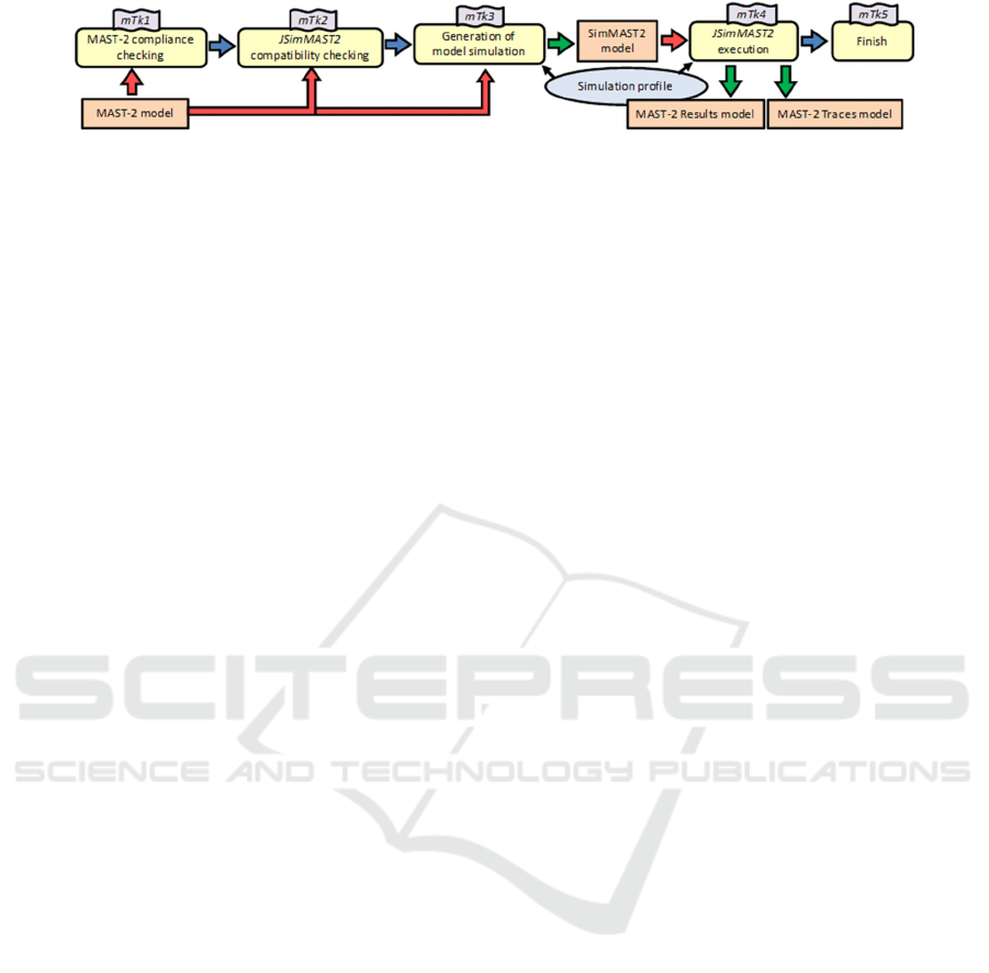
Figure 7: mTasks constituting the Simulation mTool.
modelling the traces generated by the simulation tool
complete the MAST modelling core.
In the current available version of the suite, the
analysis tools are implemented using Ada and Java
and are launched from primitive Ada/Java GUIs or
even from command line, using input models based
on plain text or XML. The MDDE approach is really
suitable in order to develop an MDSE environment
for MAST, since it does not require for the authors
of MAST, experts in the real-time analysis domain,
a deep knowledge of the MDSE technologies.
4.2 Processes in MDDE-MinMAST2
The environment currently provides three processes
or mTools: i) Creation of the MAST-2 model of an
RTS; ii) Schedulability analysis; iii) Simulation of
temporal behaviour. Given a MAST-2 model of a
RTS created by means of the first process, the
second one allows the application of schedulability
analysis based on different techniques implemented
in the MAST-1.x tools (Ada), whereas the third one
allows to simulate the temporal evolution of the
system using the JSimMAST tool (Cuevas and
Drake, 2010) (Java). Both processes generate a
MAST-2 Results model, and the simulation may
also produce a MAST-2 Traces model. The rest of
this section details the simulation mTool.
Figure 7 shows the internal composition of the
tool as a sequence of mTasks. Before applying the
simulation itself, the process verifies the correction
of the MAST-2 input model (mTk1) by checking the
satisfaction of the integrity constraints imposed on
the MAST-2 meta-model, and also its compatibility
with the JSimMAST tool (mTk2) by checking the
constraints imposed by this specific tool. Once we
have checked the model is correct, a simulation
execution profile must be chosen, and based on that
selection, the input model is transformed (mTk3)
into a simulation model (compliant to the
SimMAST2 meta-model). After that, the process
means the proper execution of the simulation (mTk4)
according to the established profile.
In its current status, the environment defines five
mTaskTypes that can be reused to formalize different
mTools:
M2M constraints verification (Cuevas et al.
2016). This first one is exposed in detail below.
MAST-2 SimMAST2 transformation.
Simulation execution (JSimMAST launch). This
is an example of task that adapts an internal
gadget (a Java application).
Schedulability analysis execution (MAST-1.x
external tools launch). This is an example of task
that adapts an external gadget (an Ada
application).
Process finish.
M2M Verification. It consists of an M2M
transformation that checks if a model verifies a set
of constraints imposed on its meta-model, generating
a diagnosis model as result (Cuevas et al. 2016).
This mTask is atomic and defines the following
configuration parameters: location of the model to
be verified, location of the generated diagnosis
model and the constraints package against the
checking is performed. This mTaskType represents a
paradigmatic example of reutilization, since mTasks
of this type can take part in multiple mTools of
different nature that, prior to model processing,
require the models to be checked against a certain
set of constraints. This is what happens specifically
in our example environment, since two tasks of this
type are used in the simulation tool (mTk1 and
mTk2), as shown in Figure 7, but also the
schedulability analysis tool (not included in the
paper) uses this mTaskType.
5 RELATED WORK
The methodology introduced in (Gamboa and
Syriani, 2016) presents some parallelisms with the
work presented here, both regarding the goal of
easing the usage of MDSE and the methodology
itself, based on the semi-automatic execution of
workflows (Russell et al., 2006). However, it is
mainly focused on the final users of MDSE
environments, both language engineers and domain-
specific modellers, trying to speed up their daily
activities. In contrast, our work is more oriented to
the adoption of MDSE by those software engineers,
typically not experts in MDSE, that are responsible
for the design and implementation of new
Automating the Customization of Model-Driven Software Engineering Environments
343

development environments to support the domain-
specific methodologies proposed by themselves;
environments that will later be used by the final
users aforementioned.
The proposed methodology has been
implemented in its own tool (Syriani et al., 2013),
although it can be implemented on top of different
base frameworks, supporting both meta-modelling in
two levels and deep meta-modelling (De Lara and
Guerra, 2010); (Rossini et al., 2014).
6 CONCLUSIONS
The design of an MDSE environment not only
requires to design meta-models for information
formalization and tools that perform its
transformations, but also to design processes that
encompass sets of models generated by the
concatenated and/or iterative application of tools
under the user supervision. Although the conception
of these processes is responsibility of the designer of
environments, their implementation based on the
MDSE infrastructure may be, due to its complexity,
beyond his expertise and knowledge. MDDE is
proposed to alleviate this task. It constitutes a
generic conception for MDSE environments that
includes the definition of a reference model for the
design of environments and a set of supporting
resources that facilitate the specification and
implementation of environments. By using the
MDDE reference model, the processes are
formulated as models. Such models describe in turn
the models and tools that take part in the process as
well as the interactions required to the user. These
descriptive models are interpreted by an internal tool
provided by the environment, allowing its automatic
(but assisted) execution. Automating the generation
of complex tools based on simpler primitive tools
available in the environment facilitates the
customization of the environments and its adaptation
to the particular aspects of each domain-specific
field. Besides, with this approach, the primitive tools
of the environments can be simpler and hence, easier
to maintain, design and reuse.
The validation of the MDDE approach is in its
initial phase, since only one implementation has
been developed as a proof of concept. It has been
built on top of Eclipse and its target domain is the
analysis and design of RTS using the MAST
methodology. Different domains must be addressed
for identifying possible extension points for MDDE,
extending it as a consequence and building new
corresponding implementations.
ACKNOWLEDGEMENTS
This work has been funded in part by the Spanish
Government under grant number TIN2014-56158-
C4-2-P (M2C2).
REFERENCES
Cuevas, C., 2016. Metaherramientas MDE para el diseño
de entornos de desarrollo de sistemas distribuidos de
tiempo real. PhD Thesis. Universidad de Cantabria.
Cuevas, C. et al., 2012. MAST 2 Metamodel. Internal
Report. Available at http://www.istr.unican.es/
members/cesarcuevas/phd/artifactsMAST2.html.
Cuevas C., Drake J.M., 2010. JSIMMAST: Java Simulator
for MAST Models. Available from:
http:istr.unican.es/jsimmast [September 2016].
Cuevas, C., López Martínez, P., Drake, J.M., 2016.
Model-driven approach for verifying conformity of
models in the presence of constraints. 4th
International Conference on Model-Driven
Engineering and Software Development, pp. 455-466.
De Lara, J., Guerra, E., 2010. Deep meta-modelling with
MetaDepth. In Objects, Models, Components,
Patterns, Anonymous. Springer, pp. 1-20.
Eysholdt, M., Behrens, H., 2010. Xtext: Implement your
language faster than the quick and dirty way. ACM
International Conference Companion on Object
Oriented Programming Systems Languages and
Applications Companion, pp. 307-309.
Gamboa, M.A., Syriani, E., 2016. Automating activities in
MDE tools. 4th International Conference on Model-
Driven Engineering and Software Development, pp.
123-133.
González Harbour, M., Gutiérrez García, J.J., Palencia
Gutiérrez, J.C., Drake Moyano, J.M., 2001. MAST:
Modelling and Analysis Suite for Real-Time
Applications. 13th Euromicro Conference on Real-
Time Systems, IEEE, pp. 125-134.
González Harbour, M. et al, 2016. MAST: Modelling and
Analysis Suite for Real-Time Applications. Available
from: http://istr.unican.es/mast [September 2016].
Rossini, A., de Lara, J., Guerra, E., Rutle, A., Wolter, U.,
2014. A Formalisation of Deep Metamodelling.
Formal Aspects of Computing, vol. 26, pp. 1115-1152.
Russell, N., Ter Hofstede, A. H., Mulyar, N., 2006.
Workflow Controlflow Patterns: A revised view. BPM
Center Report BPM-06-22.
Schmidt, D. C., 2006. Guest editor's introduction: Model-
Driven Engineering. Computer, vol. 39, pp. 25-31.
Syriani, E., Vangheluwe, H., Mannadiar, R., Hansen, C.,
Van Mierlo, S., Ergin, H., 2013. AToMPM: A web-
based modeling environment. In Demos/Posters/
StudentResearch@ MoDELS, 2013, pp. 21-25.
MODELSWARD 2017 - 5th International Conference on Model-Driven Engineering and Software Development
344
