
Image Resolution Enhancement based on Curvelet Transform
Zehira Haddad
1
, Adrien Chan Hon Tong
1
and Jaime Lopez Krahe
2
1
DTIM, The French Aerospace Lab, ONERA, Palaiseau, France
2
CHART/THIM, Paris 8 University, Saint Denis, France
{zehira.bousseksou, adrien.chan_hon_tong}@onera.fr, jlk@univ-paris8.fr
Keywords: Image Super Resolution, Interpolation, Curvelet Transform, Stationary and Discrete Wavelet Transform,
Image Fusion.
Abstract: We present an image resolution enhancement method based on Curvelet transform. This transform is used
to decompose the input image into different subbands. After this decomposition, a nonlinear function is
applied to the Curvelet coefficients in order to enhance the content of the different frequency subbands.
These enhanced frequency subbands are then interpolated. We increase the enhancement results by a fusion
of the obtained data and the interpolated input image. An image database is used for experiments. The visual
results are showing the superiority of the proposed technique compared to two state-of-art image resolution
enhancement techniques. These results have been confirmed by quantitative image quality metrics.
1 INTRODUCTION
Image resolution enhancement is an active field of
research. The main goal of this research is to remedy
the problems related to the image acquisition device
(Suganya et al., 2013), to the limited size of digital
image sensor or to the poor conditions of image
acquisition. Furthermore, the increasing ever more
important of screen sizes makes this problematic
more current.
The resolution is an important aspect of image.
Many techniques are proposed in order to enhance
the image resolution and are specifically dedicated
to super resolution. These techniques affect many
fields and different kinds of images. This is the case
of satellite images where the resolution enhancement
permits to extract more information of these images
(Suganya et al., 2013), (Abirami et al., 2013),
(Harikrishna et al., 2012). The same applies to
medical images where the goal is to facilitate the
radiologist diagnosis and interpretation (Muna et al.,
2011), (Hanan et al., 2011).
One of the most classical methods of image
resolution enhancement is the image interpolation.
This commonly technique permits to increase the
number of pixels in an image using known data
values to estimate unknown data values. Therefore,
it has been widely used in various imaging
applications such as facial reconstruction (Muna et
al., 2011), description coding (Hanan et al., 2011),
and image resolution enhancement (Carey et al.,
1999), (Demiral et al., 2010), (Xie et al., 2003).
The principal image interpolation techniques are
nearest neighbor interpolation, bilinear interpolation,
and bi-cubic interpolation. However, these well-
known techniques present some visual drawbacks
which are mainly due to the loss on the high image
frequency components corresponding to the edges.
In fact, we observe a smoothing in the interpolated
image. The principal goal of the actual researches is
to ameliorate the image quality of super resolution
by preserving the edge information. In this purpose,
different works involving frequency domain instead
of spatial domain have been proposed.
Consequently, the image is first converted to
frequency domain, treated and then converted back
to spatial domain. Fourier domain which is the basic
frequency domain is more appropriate for spectral
filtering by removing particular image frequencies.
Wavelet domain which is a time frequency domain
separates the image components into separated
images representing both spatial and frequency
information.
The wavelet transform has been used
successfully in image resolution enhancement and
various approaches resulting therefrom (Birare et al.,
2010). Many approaches such as that of G.
Anbarjafari and H. Demirel use a combination of the
Discrete Wavelet Transform (DWT) and
interpolation. These techniques reduce some
Haddad Z., Tong A. and Krahe J.
Image Resolution Enhancement based on Curvelet Transform.
DOI: 10.5220/0006127201670173
In Proceedings of the 12th International Joint Conference on Computer Vision, Imaging and Computer Graphics Theory and Applications (VISIGRAPP 2017), pages 167-173
ISBN: 978-989-758-225-7
Copyright
c
2017 by SCITEPRESS – Science and Technology Publications, Lda. All rights reserved
167

drawbacks. However, it introduces an aliasing
caused by the used interpolation in high frequency
wavelet sub-bands (Bagawade et al., 2012),
(Venkata et al., 2014). Other approaches combine
DWT and Stationary Wavelet Transform (SWT) in
order to preserve more the edges of image (Hasan et
al., 2011), (Battula et al., 2012). Note however that
the wavelet transform and other classical multi-
resolutions decompositions like Laplace pyramid,
form actually a restricted and limited category of
multidimensional signal representation. Indeed,
other more recent works have shown that it is
possible to define larger multiscale representations
establishing new transforms more suitable for the
representation of geometric structures and edges
(Tripathi et al., 2014). These multiscale
decompositions operate according to many
frequency directions. The proposed super resolution
approach is based precisely on a transform of this
new transform generation, the Curvelet transform.
This transform, in addition to its multiscale character
uses much directional information, which allows for
upon decomposition, images containing more
details. All these features make this transform the
one that best represents the curves and contours in
an image. Given the importance of edges and detail
information in image resolution enhancement, we
opt for the use of this transform for the super
resolution problematic.
This paper is organized as follows; in section 2
Curvelet transform is briefly introduced. Section 3 is
dedicated to the image resolution enhancement
approaches. The proposed Curvelet based image
resolution enhancement is introduced in section 4.
Section 5 shows experimental results with
comparison and analysis. Finally, section 6 is
devoted to conclusion and perspectives.
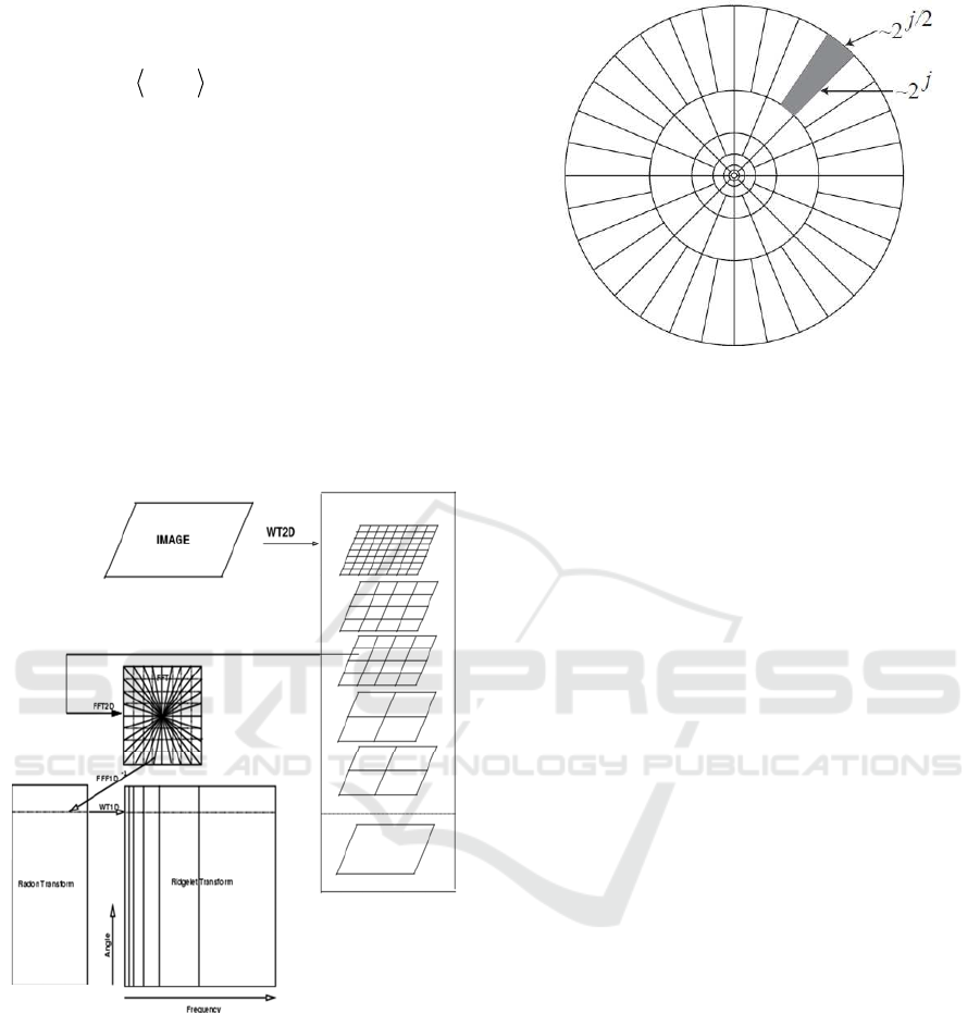
2 CURVELET TRANSFORM
Wavelet transform is adapted to the discontinuities
description of mono dimensional signals, but this
property is not true if the dimension increase. In
image processing, wavelets are used in separable
manner on the horizontal and vertical axes, which
generates a partial decorrelation of the image giving
many high energy coefficients along contours or
edges. To overcome this problem, several works was
continued in order to find which transform can filter
directly along the image contours. Thus many
transform have been proposed (Tripathi et al., 2014).
There are two major types of approaches, adaptive
and non-adaptive approaches. The first is based on
fixed and directional banks of filter which permit
image analysis at fixed positions, scales and
orientations. The second is based on an adaptive
approach from a geometric model providing local
analysis direction.
The Curvelet transform belong to the non-
adaptive approaches. This transform is derived from
Ridgelet transform.
Ridgelet coefficients (Land et al., 1986) are
obtained by applying 1D wavelet transform to all
image projections corresponding to Radon
transform. In Summary, Ridgelet transform is a 1D
wavelet analysis on slices of Radon transform where
the angle q is fixed. Continuous Ridgelets are
defined by the following formula.
12 ,, 12 12
,, , ,
ab
Rf a b f x x x x dx dx
(1)
When
1
2
,,
cos sin /
12
ab
ax x ba
is
1D wavelet constructed along a line oriented and
defined by the fallowing equation :
cos sin
12
x
xb
(2)
Their link with Radon transform is represented
by the following equation:
1
2
,, , /Rf a b Rf r a t b a dt
(3)
When Rf is the Radon transform defined by :
Rf (t,θ)=∫ f(x
1
,x
2
) δ(x
1
sinθ + x
2
cosθ - t) dx
1
dx
2
(4)
Ridgelet transform has been established to
analyze the objects that have discontinuities in
straight lines. The basic idea of Curvelet transform is
that a curve (contour) can be represented by several
segments of straight line. So, an image may contain
locally rectilinear contours. Ridgelet Analysis being
a multiscale analysis in each radial direction, the
Curvelet principle is to develop a multiscale analysis
using normalized and transported Ridgelets with
various scales.
We define a Curvelet as a function :
12
,
x
fxx
(5)
of scale 2
-j
, and orientation θ
l
, and position:
,
1/2
,1 2
2, 2
jl
jj
kl
xRkk
(6)
with R
θ
the rotation by θ and R
θ
-1
its transpose, by:
,
,,
l
jl
jlk j k
xRxx
(7)
VISAPP 2017 - International Conference on Computer Vision Theory and Applications
168
Cuvelet transform coefficients are defined by
Candes & Dohono:
2
,, ,,
,, ,
ilk ilk
cjlk f fx xdx
(8)
The various steps of the first implementation of
Curvelet transform are:
1) Decomposition into different J sub-bands
2) Partitioning
3) Ridgelet analysis (Radon transform + 1D
wavelet transform).
So, the block size B can change from a subband
k to another according to the following algorithm:
Initialize the block size B1 = Bmin.
For j=1 ,…J, for each high frequency image:
Partition subbands Wj into blocks Bj. Apply locally
the Ridgelet transform on each block:
If j mod 2 = 1 , Bj+1 = 2Bj ,
Otherwise, Bj+1 = Bj
Figure 1: Curvelet transform.
The implementation of the second generation
Curvelet transform consists of three steps:
Apply 2D FFT to obtain the Fourier samples
12
ˆ
,
f
ii
For each scale j and angle l, compute the
windowed frequency component and wrap it around
the origin
12 , 12
ˆ
ˆ
,,
jl
f
ii u ii
;
Compute the inverse 2D FFT in order to obtain
discrete Curvelet transform coefficients.
The windowing function
,12
ˆ
,
jl
uii
gives rise to
the frequency tiling as shown in Figure 2.
Figure 2: Curvelet transform partitionning.
3 IMAGE ENHANCEMENT
APPROACHES
We take a care to apply this function just on the high
frequency subbands and no on the low frequency
subband.
The image enhancement is a great area of
research. In (Land et al., 1986), Land creates a
model for human color constancy named the retinex
concept. There are SSR (Single Scale Retinal)
methods and MSR (Multiscale Retinex) methods
which combine several SSR outputs in order to
obtain a single output image which presents a good
dynamic range compression and also color
constancy and good tonal rendition. The Multiscale
Retinex presents the multiresolution concept
applying to the contrast enhancement. It
accomplishes dynamic range compression and is
used for different image processing domains. The
corresponding approach is detailed in (Barnard et al.,
1999). Otherwise, Velde in (Velde et al., 1999)
Velde proposes to use the wavelet transform for
enhancing the faintest edges and keeping untouched
the strongest. This method consists of decomposing
the image using the dyadic wavelet transform. The
gradient Gj,k at each scale j and at each pixel
location k is calculated from the wavelet coefficient
relative to the horizontal and vertical wavelet bands.
Then the two wavelet coefficients at scale j and
at pixel position k are multiplied by:
y (Gj,k)
where y is defined by
y(x) = (m/c)p if |x| < c
y(x) = (m/|x|)p if c ≤ |x| < m
y(x) = 1 if |x| ≥ m
(9)
Image Resolution Enhancement based on Curvelet Transform
169
p determines the degree of nonlinearity in the
nonlinear rescaling of the luminance, and must be in
[0, 1].
Coefficients larger than m are conserved. The c
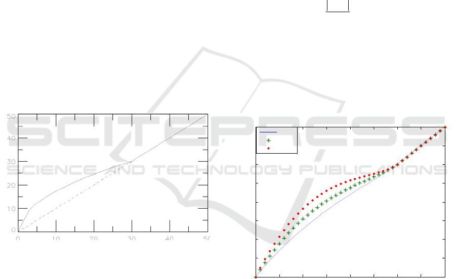
parameter corresponds to the noise level. Figure 3
shows the modified wavelet coefficients versus the
original wavelet coefficients for a given set of
parameters (m =30, c = 3, and p = 0,5). Finally, by
applying the inverse wavelet transform from the
modified wavelet coefficients, we obtain the
enhanced image. This work represents one of the
first to introduce the application of non-linear
function in order to enhance the image quality by
using a multiscale domain. Furthermore, other works
use the same idea in order to enhance the image
quality. For example, Stark et al in (Starck et al.,
2003) proposes a gray and color contrast
enhancement by using the cruvelet transform.
Similarly, Cherifi et al in (Cherifi et al., 2010) works
on a color contrast enhancement method based on
steerable filters. The basic idea of the proposed
approach is to use tools that have proven their
efficiency for image enhancement (the use of
nonlinear function) in order to use it for another
purpose which is the image resolution enhancement.
Figure 3: Enhanced coefficients versus original
coefficients. Parameters are m =30, c = 3, and p = 0,5.
4 THE PROPOSED APPROACHE
One of the major problems in image resolution
enhancement techniques concerns the edge quality
in an image. In fact, the most of these techniques
don’t preserve the sharpness of edges. In order to
increase the quality of the image of super resolution,
using a tool that enhances the edges is essential.
Curvelet transform is a multiscale and
multidirectional transform. As indicated by its name,
it is the transform which best represents the curves
and the contours in an image. The Curvelet
decomposition generates different images, one
image corresponding to low frequency band and set
of images corresponding to high frequency bands
with different orientations. Edges which correspond
to high frequencies are represented with very rich
information in Curvelet decomposition. For this
reason, we choose to use this transform in the
proposed image resolution enhancement method.
The proposed image resolution enhancement
approach firstly consists in decomposing the image
by Curvelet transform into different frequency
subbands resulting to different scales and different
orientations. Then, we enhance edges present in the
different high frequency images of the Curvelet
decomposition by using a nonlinear function
defining by the following formula:
(, )
(, ) 1 (, )
(, )
p
xi j
Gxi j xi j x M
Ri j
M
xotherwise
(10)
Where:
x(i,j) is the input image;
M the upper limit of nonlinear enhancement;
G the gain factor;
p defining the rate of attenuation towards M.
Figure 4 represents the enhancement function.
0 5 10 15 20 25 30 35 40
0
5
10
15
20
25
30
35
40
G=0,5
G=1
G=1,5
Figure 4: Enhancement function for M=30, p=1,5 and
different values of G.
We take a care to apply this function just on the
high frequency subbands and no on the low
frequency subband.
The translated information by Curvelet
coefficients says how they are aligned in the real
image. Indeed, more accurately a Curvelet is aligned
with a given curve in an image; higher is its
coefficient value. By applying the proposed
function, we increase moderately the coefficients in
order to enhance the edges. After enhance the edges
VISAPP 2017 - International Conference on Computer Vision Theory and Applications
170
images, the interpolation of image resulting of the
Curvelet decomposition is done by applying bicubic
interpolation of factor α. These steps are represented
by the dotted group in figure 5. We can stop here
and use the resulting image. However, we propose a
second approach which consists to fusion the
obtained image with the interpolated original image
by taking the maximum value component (global
scheme of figure 5).
The choice of bicubic interpolation method
instead of bilinear interpolation or nearest neighbor
is done because images resampled with this
interpolation are smoother and have fewer
interpolation artefacts, especially when speed is not
an issue.
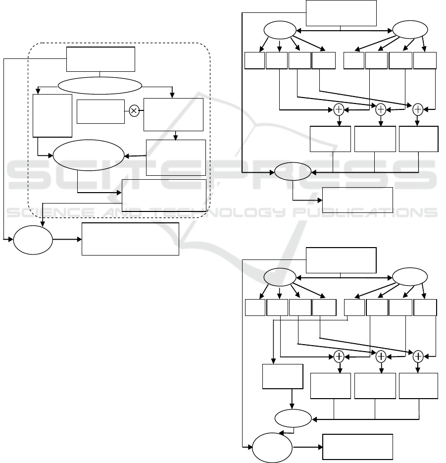
Interpolatio
n factor α
Low resolution image
(m×m)
Curvelet transform
Estimated image resolution
enhanced by curvelet
(
αm×α
m
)
Image
fusion
Enhanced images
of high frequency
Curvelet subbands
Inverse
Curvelet
High resolution image (αm×αm)
resulting from Curvelet
enhancement and image fusion
Low
frequency
Curvelet
image
Enhancement
function
Images of high
frequency
Curvelet subbands
Interpolation
factor α
Figure 5: The proposed approach.
5 EXPERIMENTAL RESULTS
For experiment, we use a database of twelve images.
These images are classical and well known in image
processing validation process. All the images are
gray scale and have 512*512 pixels. In order to
estimate the image quality, we use two image quality
measures: the classical PSNR and the structural
similarity index SSIM. In order to compare the
proposed approaches to other performant
approaches, we recall succinctly the image
resolution enhancement based on DWT and SWT
transform.
5.1 Image Resolution Enhancement
based on DWT and SWT
The input low resolution image is decomposed
through the DWT and SWT into four subbands
represented by LL (low-low), LH (low-high), HL
(high-low) and HH (high-high) each.
We summarize in the diagram of figure 6 and
that of figure 7, the principle steps of two
approaches based on DWT and SWT transform
(Tripathi et al., 2014).
Interpolation
facteu2
Interpolation
facteur2
Interpolation
facteur2
Interpolation factor α/2
Interpolation
factor α/2
Low resolution image
(m×n)
SWT
DWT
Estimated
HH
Estimated
LH
Estimated
HL
IDWT
High resolution
image (αm×αn)
HH LH
L H
LH HH LL HL
Figure 6: Image resolution enhancement based on DWT
and SWT.
Interpolation
facteurα
Interpolatio
n facteur2
Interpolation
facteur2
Interpolation factor α/2
Interpolation
factor α
Low resolution image
(m×n)
SWT
DWT
Interpolation
facteur2
Estimated
LL
Image
fusion
Estimated
HH
Estimated
LH
Estimated
HL
IDWT
High resolution
image (αm×αn)
HH LH
L H
LH HH LL HL
Figure 7: Image resolution enhancement based on DWT
and SWT and image fusion.
Image Resolution Enhancement based on Curvelet Transform
171
5.2 Image Resolution Enhancement
Results
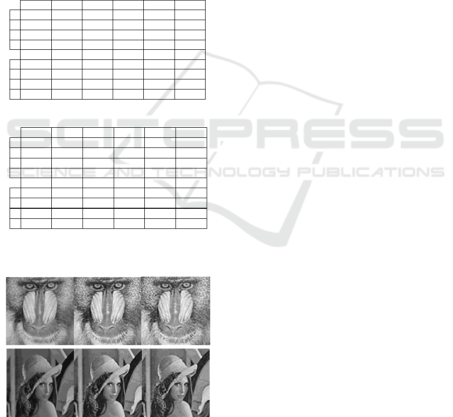
Tab1 and tab2 present PSNR and SSIM results of
the proposed image resolution enhancement
compared to the two approaches presented above.
(A) corresponds to DWT and SWT based approach.
(B) corresponds to DWT, SWT and image fusion
based approach. Our results correspond to (C) and
(D). In (C), we have the proposed approach based on
Curvelet enhancement and (D) the proposed
approach based on Curvelet enhancement and image
fusion.
Table 1: PSNR of resolution enhanced images (for α=4).
I1 I2 I3 I4 I5 I6
A 14,89 15,87 12,68 13,69 15,63 17,49
B 16,59 18,01 13,68 16,21 17,61 21,33
C
22,57 24,33 21,95
22,37 24,88 22,68
D 20,85 21,69 21,59
22,57 25,49 25,05
I7 I8 I9 I10 I11 I12
A 16,80 14,63 14,07 15,79 13,91 13,03
B 19,89 16,05 19,64 17,90 14,62 19,94
C 21,32
23,81
20,07
21,80 20,56 23,68
D
22,22
23,02
23,80
20,82 17,76 23,64
Table 2: SSIM of resolution enhanced images (for α=4).
I1 I2 I3 I4 I5 I6
A 0,558 0,673 0,562 0,415 0,493 0,388
B 0,706 0,773 0,649 0,540 0,619 0,503
C 0,768 0,895 0,785 0,686 0,764 0,628
D
0,826 0,903 0,794 0,704 0,780 0,647
I7 I8 I9 I10 I11 I12
A 0,295 0,444 0,318 0,275 0,424 0,409
B 0,399 0,572 0,483 0,379 0,529 0,757
C 0,551 0,703 0,571 0,519 0,641 0,806
D
0,565 0,728 0,629 0,528 0,655 0,883
Figure 8 presents two visual examples of the
proposed approach compared to DWT and SWT
based approaches.
Figure 8: Visually results of high image resolution
obtained by DWT and SWT based approaches (left) and
the proposed approach (right).
The obtained results demonstrate clearly the
superiority of the proposed approaches compared to
the others. However, we can notice that PSNR
results are shared between (C) and (D), while the
SSIM results (metric more sophisticated and more
effective than classical PSNR) show clearly that the
best approach is (D).
6 CONCLUSIONS
We propose an image resolution enhancement
approach based on Curvelet transform. Since the
main inconvenient of the majority of the literature
approaches concern the edges quality, we propose to
use a transform which is especially dedicated to the
good representation of image edges. For this, we
enhance the Curvelet coefficients of each subband
by applying an enhancement function. The obtained
results demonstrate also that by applying a fusion
between the resulted image by Curvlet enhancement
and the interpolated image, we observe better
results. We compare these proposed approaches with
two other approaches in the literature in term of
quality by using PSNR and SSIM. The obtained
results show that the proposed method is
considerably better than the other techniques.
As perspective, we propose to test the proposed
method on other types of images like satellite,
medical images. Also, we propose to work on
images containing text recognition. In fact, in this
type of images, we must generally use the super
resolution image in order to extend the text, this is
necessary for a good text detection and recognition
by OCR. Furthermore, the text in these images (like
geographical images) is generally confused with the
image contours and the use of the proposed
approach could give good results. So, the proposed
approach gives a solution to understand the image
content in small images in order to achieve the
desired objective.
REFERENCES
Suganya. P, Mohanapriya. N, Vanitha. A, 2013, Survey on
Image Resolution Techniques for Satellite Images,
International Journal of Computer Science and
Information Technologies, Vol. 4 no.6, pp. 835-838.
Abirami. A, Akshaya. N, Poornakala. D, Priyanka. D,
Ram kumar. C, 2013, Enhancement of Satellite Image
Resolution With Moving Objects, IOSR Journal of
Electronics and Communication Engineering (IOSR-
JECE), Volume 4, Issue 6, PP 22-27.
VISAPP 2017 - International Conference on Computer Vision Theory and Applications
172

Harikrishna. O, Maheshwari. A, 2012, Satellite Image
Resolution Enhancement using DWT Technique,
International Journal of Soft Computing and
Engineering (IJSCE) Volume-2, Issue-5.
Dr. Muna F. Al-Samaraie , Dr. Nedhal Abdul Majied Al
Saiyd, 2011, Medical colored image enhancement
using wavelet Transform followed by image
sharpening, Ubiquitous Computing and
Communication Journal, Volume 6 Number 5.
Hanan Saleh S. Ahmed and Md Jan Nordin, 2011,
Improving Diagnostic Viewing of Medical Images
using Enhancement Algorithms, Journal of Computer
Science, vol 7 no.12, 2011.
Carey. W. K., Chuang; D. B., Hemami. S. S, 1999,
Regularity preserving image interpolation, IEEE
Transaction on Image Processing, vol.8, no.9,
pp.1293-1297.
Demiral. H and Anbarjafari. G, 2010, Image super
resolution based on interpolation of wavelet domain
high frequency sub-bands and spatial domain input
image, ETRI Journal, vol. 32, no. 3, pp.390-394.
Xie. Z, 2003, A wavelet based algorithm for image super
resolution, B. S, University of science and technology
of China.
Birare. S. D, Nalbalwar. S. L, 2010, Review on super
resolution of images using wavelet transform
International Journal of Engineering Science and
Technology, vol.2, no. 12, pp. 7363-7371.
Bagawade Ramdas, Bhagawat Keshav, Patil Pradeep,
2012, Wavelet Transform Techniques for Image
Resolution Enhancement: A Study, International
Journal of Emerging Technology and Advanced
Engineering, Volume 2, Issue 4.
Venkata ramana. S , Narayana reddy, S, 2014, A Novel
Method to Improve Resolution of Satellite Images
Using DWT and Interpolation, International Journal
of Advanced Research in Electrical, Electronics and
Instrumentation Engineering, Vol. 3, Issue 1.
Hasan Demirel, Gholamreza Anbarjafari, 2011, Image
Resolution Enhancement by Using Discrete and
Stationary Wavelet Decomposition” IEEE
Transactions On Image Processing, vol. 20, no. 5.
Battula. R. V. S. Narayana, K. Nirmala, 2012, Image
Resolution Enhancement by Using Stationary and
Discrete Wavelet Decomposition I.J. Image, Graphics
and Signal Processing, vol. 11,pp. 41-46.
Tripathi. N, Gopal Kirar. K, 2014, Image Resolution
Enhancement by Wavelet Transform Based
Interpolation and Image Fusion”, International
Journal of Advanced Research in Computer Science
and Software Engineering, Volume 4, Issue 8, pp.
318-323.
Land. E, 1986, Recent advances in retinex theory, Vis.
Res., vol. 26, no. 1, pp. 7–21.
Barnard. K and Funt. B, 1999, “Investigations into multi-
scale retinex,” in Color Imaging: Vision and
Technology. New York: Wiley, pp. 9–17.
Velde, K. V, 1999, “Multi-scale color image
enhancement,” in Proc. Int. Conf. Image Processing,
vol. 3, pp. 584–587.
Starck, J., Murtagh, F., Candes, E.J., and Donnoho, D.L,
2003: Gray and color image contrast enhancement by
the curvelet transform. IEEE Trans. Image
Processing; 12(6):706-17.
Cherifi. D, Azeddine Beghdadi, Belbachir. A. H, 2010:
Color contrast enhancement method using steerable
pyramid transform. Signal, Image and Video
Processing 4(2): 247-262.
Image Resolution Enhancement based on Curvelet Transform
173
