
Superposition of Qualitative Rectangles using a Quantitative Model
Takeaki Kato
∗
, Sosuke Moriguchi and Kazuko Takahashi
School of Science & Technology, Kwansei Gakuin University, 2-1, Gakuen, Sanda, 669-1337, Japan
Keywords:
Qualitative Spatial Reasoning, Superposition, Relative Direction, Knowledge Representation and Reasoning.
Abstract:
This paper describes an approach to qualitative problem-solving using the quantitative method in spatial rea-
soning. We consider the superposition of two objects, such that pre-specified parts of the objects are visible.
First, we qualify an object to create a model. It is expressed as a matrix of tiles, which are either black or
white depending on the visibility requirement. We use this to determine the location of two objects. This
process involved quantitative treatment. We describe a sound and complete algorithm that provides quantita-
tive solutions and implemented it as a system with a graphical user interface. Then, we extend this algorithm
so that we may search for a better solution considering a qualitatively equivalent model of the objects; that
is, the topological relationships between the black and white regions are identical. This approach is useful
for analyzing or designing a projection of three-dimensional objects onto a two-dimensional plane, because
it not only reduces the computational expense but also provides a better fit with common sense and human
reasoning.
1 INTRODUCTION
Many problems involve locating multiple objects in a
finite area with superposition or folding, where the
geometry may be more complicated than simply a
two-dimensional plane. For example, we may wish
to allocate multiple windows on a screen of limited
area (Konishi and Takahashi, 2012), determine the
location of gates or codes in designing logical cir-
cuits (Lapaugh, 1996), place labels of building names
in maps (Freeman, 1991; Li et al., 1998), or arrange
an attractive display for goods. These problems are
related to so-called “packing problems,” which repre-
sent a class of optimization problems of pack objects
into containers. Many efficient algorithms have been
developed for packing problems (Lodi et al., 2002;
Birgin et al., 2010), the aim of which is usually ei-
ther to pack a single container as densely as possible,
or to pack all objects using as few containers as pos-
sible. However, in the above kinds of problems, the
aspect of visibility is accompanied; that is, an object
may have a part that should be visible and another
part that may not be; and the optimal solution is deter-
mined depending not only on the density or the num-
ber of containers but also on where specific parts are
located. This can be reduced to a problem of super-
∗
Currently, NEC Networks & System Integration Cor-
poration
position, in which the former part is visible and the
latter part is hidden. With such problems, it is easier
to understandhow to determine approximatelythe po-
sitions of the connected parts or superposed parts of
objects at an early stage of the design process than to
compute this using precise data. More efficient meth-
ods for handling these kinds of problem are required
with the increase in the number of occasions on which
three-dimensional data are analyzed or designed.
Previously, we reported a qualitative method that
handles objects consisting of should-be-visible parts
and may-be-hidden parts (Konishi and Takahashi,
2012; Ghourabi and Takahashi, 2015a; Ghourabi and
Takahashi, 2015b). The method looks for a super-
position that satisfies these constraints. Here the
term “qualitative” means representation and reason-
ing without using precise data. In these studies, we
use a rectangle in which the size and ratio of the edges
are variable as a target object, and consider objects as
rectangles consisting of several tiles. This is repre-
sented in matrix form, where each element requires
the attribute of visibility. We define the relative direc-
tion and distance of two tiles as a basic relationship,
and perform reasoning on this representation.
Consider the superposition of the object shown in
Figure 1(b) onto the object shown in Figure 1(a) with-
out rotation, so that the white parts are visible. We
obtain five solutions, as shown in Figures 1(c)–(g),
Kato T., Moriguchi S. and Takahashi K.
Superposition of Qualitative Rectangles using a Quantitative Model.
DOI: 10.5220/0006123404230430
In Proceedings of the 9th International Conference on Agents and Artificial Intelligence (ICAART 2017), pages 423-430
ISBN: 978-989-758-220-2
Copyright
c
2017 by SCITEPRESS – Science and Technology Publications, Lda. All rights reserved
423
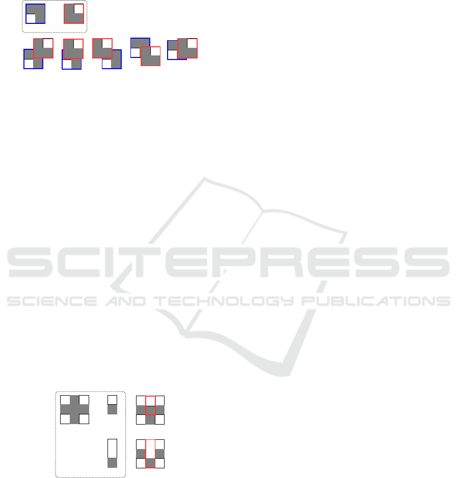
which are qualitatively different. For example, (c) is
obtained by placing the black region around the bot-
tom left corner of (b) on the black region around the
top right corner in (a).
(a) (b)
(c)
(d)
(f)
(g)
(e)
Figure 1: Qualitatively different solutions of a superposi-
tion.
We formalized an algorithm for this super-
position method using the proof assistant Is-
abelle/HOL (Ghourabi and Takahashi, 2015a). This
algorithm maps the relative direction and distance of
a pair of tiles from the lower rectangle to those in the
upper rectangle. This algorithm is sound but incom-
plete; that is, solutions may exist that cannot be found
in some cases. In this paper, the algorithm is revised
to preserve completeness and is implemented as a sys-
tem with a visual interface.
Moreover, we extend this algorithm so that it can
generate a “better” solution by regardingobjects qual-
itatively. See Figure 2. If we superpose pattern (b)
onto pattern (a) without rotation, so that white parts
are visible, we obtain (c) as one solution, by placing
(b) in the position indicated by the red frame; whereas
if we superpose pattern (d) onto pattern (a), we obtain
(e) as a solution. Here, the patterns shown in (b) and
(d) are qualitatively equivalent, because their config-
urations are the same; that is, the topological relation-
ships between the black and white regions are identi-
cal. In this case, (e) may be a better solution than (c),
as more of the black parts of (a) are hidden.
(a) (b)
(d)
(c)
(e)
Figure 2: Superposition based on regarding objects qualita-
tively.
The principle idea of our approach is that we first
determine the existence of a solution for a pair of rect-
angles by considering their configurations. This is
solved quantitativelyby using a matrix representation.
If a solution exists, then a better solution is sought us-
ing another rectangle with the same configuration.
The remainder of this paper is organized as fol-
lows. In Section 2, we describe our qualitative rea-
soning and tiling approach to create qualitative rect-
angles, and also define a matrix representation along
with the associated computations. In Section 3, we
describe a sound and complete algorithm for the su-
perposition. In Section 4, the method is expanded
to find a better solution by regarding objects quali-
tatively. Section 5 concludes the paper.
2 PRELIMINARIES
2.1 Qualitative Spatial Treatment
Numerical data such as coordinates or sizes are typ-
ically used when handling spatial data such as fig-
ures, images, and animations. This leads to a signif-
icant burden in terms of data storage and processing.
Considering the current growth in handling big spa-
tial data, an efficient approach is required. Qualitative
spatial reasoning (QSR) is one such approach to rep-
resenting spatial data without numerical data. QSR
enables reasoning via a symbolic representation; thus,
it not only reduces computationalexpense, it also pro-
vides a better fit with common sense and human rea-
soning.
There havebeen a number of studies of QSR in the
field of artificial intelligence (Stock, 1997; Cohn and
Hazarika, 2001; Cohn and Renz, 2007; Chen et al.,
2013). There are various types of QSR depending on
which aspect one is interested in; for example, direc-
tion, size, and mereology (i.e., part-whole relation-
ships). Spatial occlusion is a concept closely related
to superposition, but studies of spatial occlusion do
not consider the location of the occluded part of an
object (e.g., (Randell et al., 2001)). In our approach
to the superposition of qualitative rectangles, we fo-
cus on the relative direction between the tiles used to
construct an object. There are several existing QSR
systems that focus on the relative directions of two
objects (Goyal and Egenhofer, 2001; Renz and Mitra,
2004; Skiadopoulos and Koubarakis, 2005). Of these,
the tiling approach considers the shapes of objects
and divides the plane into rectangular tiles (Goyal and
Egenhofer, 2001; Li and Liu, 2015). We use a vari-
ation of the tiling approach that expresses directional
relations between objects with better precision.
2.2 Tiling Approach
The target object is a closed finite connected region,
which may include holes, and where the should-be-
ICAART 2017 - 9th International Conference on Agents and Artificial Intelligence
424
visible parts and may-be-hidden parts are indicated in
advance
2
.
We assume that objects are rectangles, which have
should-be-visible parts and may-be-hidden parts;
each edge of these parts is parallel either with the x-
or y-axes. We extend these edges to divide the entire
rectangle into r ∗ c tiles (1 ≤ r, c), as shown in Fig-
ure 3, where the should-be-visible part is shown in
white and the may-be-hidden part in black.
r
c
Figure 3: Tiling for an object: rectangle.
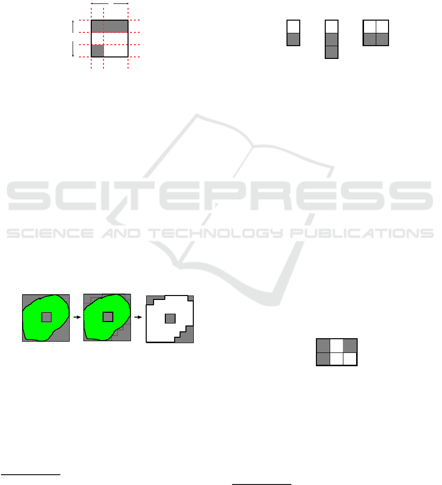
If an object cannot be described in such a simple
form, we take a minimum bounding rectangle, which
is an expression of the maximum extents of an ob-
ject within a Cartesian coordinate system. As shown
in Figure 4(a), where the green area shows a should-
be-visible part, we approximate the border lines of
objects as well as the border lines of the should-be-
visible part so that each of them is parallel with either
the x- or y-axes (Figure 4(b)). We now obtain a rectan-
gle consisting of should-be-visible parts and may-be-
hidden parts, where each of the edges of these parts
are parallel with either the x- or y-axes. Any part not
occupied by an object is regarded as a may-be-hidden
part (Figure 4(c)). We then perform a similar process,
as shown in Figure 3.
minimal bounding
rectangle
(a) (c)
(b)
Figure 4: Preprocessing for tiling an object of any shape.
For any object, we can obtain a rectangle consist-
ing of r∗c tiles (1≤ r, c) that includes no identical pat-
terns of black and white in each adjacent row or col-
umn. This rectangle is called a unit and has the con-
figuration of the target figure in the least refined form.
If additional lines are drawn between the adjacent red
parallel dotted lines in Figure 3, a rectangle consisting
of more tiles is got, which is a more refined model of
2
In previous reports, we assumed that a given object is a
rectangle; however, in principle we may consider arbitrary
geometries.
the object. For a pair of models, if their topological
configuration of black and white regions are identical,
then they are said to be qualitatively equivalent. All
models of an object are qualitatively equivalent.
For example, all figures in Figure 5 are qual-
itatively equivalent, but they are not quantitatively
equivalent. In this case, Figure 5(a) is taken as a unit.
For any object, there exists a unique unit. If a tile is
occupied by a should-be-visible part of an object, then
it is called a white tile; otherwise it is called a black
tile.
(a) (b) (c)
Figure 5: Qualitatively equivalent models.
2.3 Expression for a Unit Configuration
For a unit, each tile is referred as t
ij
, where the top
left of the unit is t
00
and the value of i increases in the
top down direction and the value of j increases in the
left-to-right direction.
Definition 2.1 (granularity). For a unit in which a row
is r and a column is c, r ∗ c is called the granularity
of the unit
3
. Let U
1
be a unit with granularity r
1
∗ c
1
,
and let U
2
be a unit with granularity r
2
∗ c
2
. If either
r
1
≤ r
2
, c
1
< c
2
or r
1
< r
2
, c
1
≤ c
2
, then it is said that
U
2
is more granular than U
1
.
The tiles of a unit are classified into black and
white tiles. Let T be a set of tiles of a unit, and
let B(T) and W (T) be sets of the black and white
tiles of T, respectively. B (T) ∪ W (T) = T and
B(T) ∩ W (T) =
/
0 hold.
Figure 6 shows a unit with granularity 2∗ 3. Let T
be a set of tiles of this unit. B (T) = {t
00
,t
02
,t
10
}, and
W (T) = {t
01
,t
11
,t
12
}.
00
t
01
t
02
t
10
t
11
t
12
t
Figure 6: Unit expression.
Let t
ij
and t
pq
be tiles of a unit with granularity
r ∗ c (0 ≤ i, p < r, 0 ≤ j, q < c). We define function
dir that computes the direction of target tile t
pq
wrt
reference tile t
ij
as follows, where k = |i− p|, h = | j−
q|:
3
Note that the meaning of “granularity” here differs
from that used in (Ghourabi and Takahashi, 2015b).
Superposition of Qualitative Rectangles using a Quantitative Model
425
dir(t
ij
,t
pq
) =
same if p = i, q = j
up
k
if p < i, q = j
down
k
if p > i, q = j
le ft
h
if p = i, q < j
right
h
if p = i, q > j
up
k
◦ left
h
if p < i, q < j
up
k
◦ right
h
if p < i, q > j
down
k
◦ left
h
if p > i, q < j
down
k
◦ right
h
if p > i, q > j
For example, in Figure 6, dir(t
02
,t
12
) = down
1
and dir(t
02
,t
10
) = down
1
◦ left
2
.
For a specific reference tile, we define a set of rel-
ative directions in which black/white tiles are located.
Definition 2.2 (Direction of B/W-tiles). For a spe-
cific tile t, D
B
(t) = ∪
t
′
∈B(T)
{dir(t, t
′
)} is called
the set of directions of B-tile wrt t, and D
W
(t) =
∪
t
′
∈W (T)
{dir(t, t
′
)} is called the set of directions of
W-tile wrt t.
For example, in Figure 6, D
B
(t
02
) =
{same, left
2
, down
1
◦ left
2
} and D
W
(t
02
) =
{left
1
, down
1
◦ left
1
, down
1
}.
3 ALGORITHM FOR
SUPERPOSITION
3.1 Superposition of a Unit
Here superposition refers to placing a foreground unit
denoted byU
f
onto a background unit denoted byU
b
,
in such a way that a tile ofU
f
is placed on a tile ofU
b
.
We define the success of superposition using di-
rections.
Definition 3.1 (Success of Superposition.). Let T
f
and T
b
be sets of tiles of a foreground unit U
f
and a
background unit U
b
, respectively. For t
f
∈ T
f
, t
b
∈ T
b
,
if D
W
(t
b
) ∩ (D
W
(t
f
) ∪ D
B
(t
f
)) =
/
0, then it is said
that superposition of t
f
on t
b
succeeds. If there exists
such a pair t
f
and t
b
, then it is said that superposition
of U
f
on U
b
succeeds.
When a superposition of t
f
on t
b
succeeds, for all
d ∈ D
W
(t
b
), there does not exist t
′
∈ T
f
such that
dir(t
f
,t
′
) = d. Intuitively, there is no tile in direction
d wrt t
f
on U
f
, where d is the direction of a white tile
wrt t
b
on U
b
.
3.2 Computing Superposition
For a specific black tile t
b
of T
b
, we generate D
W
(t
b
),
a set of directions of all white tiles wrt to t
b
. For each
element d of the set, we define a function atiles that
generates a set of tiles of T
f
an element of which can
be put on t
f
without hiding a white tile in the direction
of d
4
. That is, atiled(d) is a set of tiles that does not
have any tiles in the direction of d.
Let r∗ c be a granularity of U
f
.
atiles(same) =
/
0
atiles(up
k
) =
{t
ij
|0 ≤ i < min(k, r), 0 ≤ j < c}
atiles(down
k
) =
{t
ij
|max(0, r− k) ≤ i < r, 0 ≤ j < c}
atiles(left
k
) =
{t
ij
|0 ≤ i < r, 0 ≤ j < min(k, c)}
atiles(right
k
) =
{t
ij
|0 ≤ i < r, max(0, c − k) ≤ j < c}
atiles(dir ◦ dir
′
) = atiles(dir) ∪ atiles(dir
′
)
We then take the intersection of the obtained sets
of tiles for each d:
puton(t
b
) =
\
d∈D
W
(t
b
)
atiles(d) ⊆ T
f
.
If puton(t
b
) 6=
/
0, the superposition succeeds and
we obtain the set of solutions:
sol(T
b
, T
f
) = {(t
b
,t
f
) | t
f
∈ puton(t
b
)}.
UfUb
superposition
00
t
01
t
02
t
10
t
11
t
12
t
00
t’
01
t’
02
t’
10
t’
11
t’
12
t’
Figure 7: Superposition.
For example, in Figure 7, let
T
f
= {t
′
00
,t
′
01
,t
′
02
,t
′
10
,t
′
11
,t
′
12
} and T
b
=
{t
00
,t
01
,t
02
,t
10
,t
11
,t
12
}. B(T
b
) = {t
00
,t
02
,t
10
}.
Let t
02
be a tile that is to be superposed. Then
D
W
(t
02
) = {left
1
, down
1
◦ left
1
, down
1
}. In this
case, atiles(left
1
) is the set of tiles in U
f
to put
on t
02
without hiding t
01
, and we obtain {t
′
00
,t
′
10
}.
Similarly, atiles(down
1
◦ left
1
) = {t
′
00
,t
′
10
,t
′
11
,t
′
12
}
and atiles(down
1
) = {t
′
10
,t
′
11
,t
′
12
}. Therefore,
puton(t
02
) = atiles(left
1
) ∩ atiles(down
1
◦ le ft
1
) ∩
atiles(down
1
) = {t
′
10
} 6=
/
0, and hence the superposi-
tion of t
′
10
on t
02
succeeds.
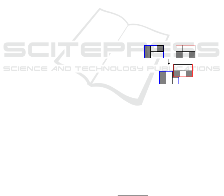
The figures obtained by these superpositions may
be identical, even if the solutions in sol(T
b
, T
f
) are
distinct. For example, in Figure 8, solutions (t
00
,t
′
02
)
and (t
10
,t
′
12
) both generate the same figure.
4
The name atiles indicates the tiles that are “allowed” to
be placed.
ICAART 2017 - 9th International Conference on Agents and Artificial Intelligence
426

UfUb
superposition
00
t
01
t
02
t
10
t
11
t
12
t
00
t’
01
t’
02
t’
10
t’
11
t’
12
t’
Figure 8: Different solutions give the same result.
3.3 Soundness and Completeness
Here we prove the soundness and completeness of the
algorithm.
3.3.1 Soundness
The following lemma indicates that, if there exists a
tile that is allowed to be placed, then no tile exists that
hides a white tile.
Lemma 3.1. Let T be a set of tiles of a unit with
granularity r ∗ c. For any direction d, if there exists
t
ij
∈ T such that t
ij
∈ atiles(d), then there does not
exist t
pq
∈ T such that dir(t
ij
,t
pq
) = d.
Proof. Assume that there exists t
pq
∈ T such that
dir(t
ij
,t
pq
) = d (0 ≤ p < r, 0 ≤ q < c). Here, we
show a proof for the case whereby d = up
k
. In this
case, k = i − p from the definition of dir. If k > r,
then 0 ≤ i < min(k, r) = r, since t
ij
∈ atiles(up
k
).
Therefore, p = i − k < i − r < 0 holds, which con-
tradicts 0 ≤ p. If k ≤ r, then 0 ≤ i < min(k, r) = k,
since t
ij
∈ atiles(up
k
). Therefore, p = i− k < 0 holds,
which contradicts 0 ≤ p. For other directions, the
proof proceeds similarly.
Theorem3.1. Let t
f
∈ T
f
andt
b
∈ T
b
. For all (t
b
,t
f
) ∈
sol(T
b
, T
f
), superposition t
f
on t
b
succeeds.
Proof. Assume that there exists (t
b
,t
f
) ∈ sol(T
b
, T
f
)
such that superposition t
f
on t
b
does not succeed.
Then there exists d such that d ∈ D
W
(t
b
)∩(D
W
(t
f
)∪
D
B
(t
f
)); that is, d ∈ D
W
(t
f
) ∪ D
B
(t
f
). Therefore,
there exists t
′
f
∈ T
f
such that dir(t
f
,t
′
f
) = d. On
the other hand, t
f
∈ atiles(d) for all d ∈ D
W
(t
b
),
from t
f
∈ puton(t
b
). There does not exist t
′
f
that
satisfies dir(t
f
,t
′
f
) = d for any d ∈ D
W
(t
b
), from
Lemma 3.1. It is a contradiction. Therefore, for all
(t
b
,t
f
) ∈ sol(T
b
, T
f
), the superposition of t
f
on t
b
suc-
ceeds.
3.3.2 Completeness
The following lemma indicates that if there exists a
tile that cannot be placed, there must exist a tile that
hides a white tile.
Lemma 3.2. Let T be a set of tiles of a unit with gran-
ularity r∗ c. For any direction d, if there exists t
ij
∈ T
such that t
ij
6∈ atiles(d), then there exists t
pq
∈ T such
that dir(t
ij
,t
pq
) = d.
Proof. Here, we show a proof for the case whereby
d = up
k
. If we assume k > r, then for all t
ij
∈ T,
t
ij
is included in atiles(d), which contradicts the con-
dition; therefore, k ≤ r. k ≤ i < r holds, since t
ij
6∈
atiles(up
k
). It follows 0 ≤ i− k < r − k < r. There-
fore, if we take p = i − k, q = j, then t
pq
∈ T and
dir(t
ij
,t
pq
) = up
k
hold. For other directions, the proof
proceeds similarly.
Theorem 3.2. Let t
f
∈ T
f
and t
b
∈ T
b
. If superposi-
tion t
f
on t
b
succeeds, then (t
b
,t
f
) ∈ sol(T
b
, T
f
).
Proof. Assume that (t
b
,t
f
) 6∈ sol(T
b
, T
f
). Then, there
exists d ∈ D
W
(t
b
) such that t
f
6∈ atiles(d) holds,
and there exists t
′
f
such that dir(t
f
,t
′
f
) = d from
Lemme 3.2. dir(t
f
,t
′
f
) ∈ D
W
(t
f
) ∪ D
B
(t
f
), and thus
d ∈ D
W
(t
f
) ∪ D
B
(t
f
). Hence, D
W
(t
b
) ∩ (D
W
(t
f
) ∪
D
B
(t
f
)) 6=
/
0, and it follows that the superposition
of t
f
on t
b
fails. It is a contradiction. Therefore,
(t
b
,t
f
) ∈ sol(T
b
, T
f
).
3.4 Effectiveness
There may be multiple solutions of the superposition
problem. Here, we take the number of black tiles hid-
den by the superposition as a measure of the evalua-
tion, because effective usage of a finite space is often
considered as a requirement.
Hereafter, we refer to a solution for the superpo-
sition described so far as a “quantitative solution” to
distinguish it from a “qualitative solution,” which will
be introduced later.
Definition 3.2 (Quantitative Solution). Let T
f
and T
b
be tiles of U
f
and U
b
, respectively. An element of
sol(T
b
, T
f
) is called a quantitative solution for the su-
perposition of U
f
on U
b
.
Definition 3.3 (Covered Tile). Let (t
b
,t
f
) ∈
sol(T
b
, T
f
). We call the black tiles hidden by
the superposition covered tiles. The number of the
covered tiles is defined as follows:
N
cov
(t
b
,t
f
) = |D
B
(t
b
) ∩
[
t
′
f
∈T
f
dir(t
f
,t
′
f
)|
It is clear that N
cov
(t
b
,t
f
) is less than or equal to
the smaller value of |B(T
b
)| and |T
f
|.
Definition 3.4 (Quantitative Optimal Solution). Let
T
f
and T
b
be sets of tiles of U
f
and U
b
, respec-
tively. For (s, s
′
), (t, t
′
) ∈ sol(T
b
, T
f
), if N
cov
(s, s
′
) <
N
cov
(t, t
′
) it is said that (t,t
′
) is a better solution than
Superposition of Qualitative Rectangles using a Quantitative Model
427
(s, s
′
). If there exists no (t, t
′
) ∈ sol(T
b
, T
f
) such that
N
cov
(s, s
′
) < N
cov
(t, t
′
) holds, then (s, s
′
) is called a
quantitative optimal solution for the superposition of
U
f
on U
b
.
For example, compare Figures 7 and 8, which
show the superpositions of the same pair of U
f
and U
b
. N
cov
(t
02
,t
′
10
) = 1 in Figure 7, whereas
N
cov
(t
00
,t
′
02
) = 2 in Figure 8. Therefore, the latter is a
better solution.
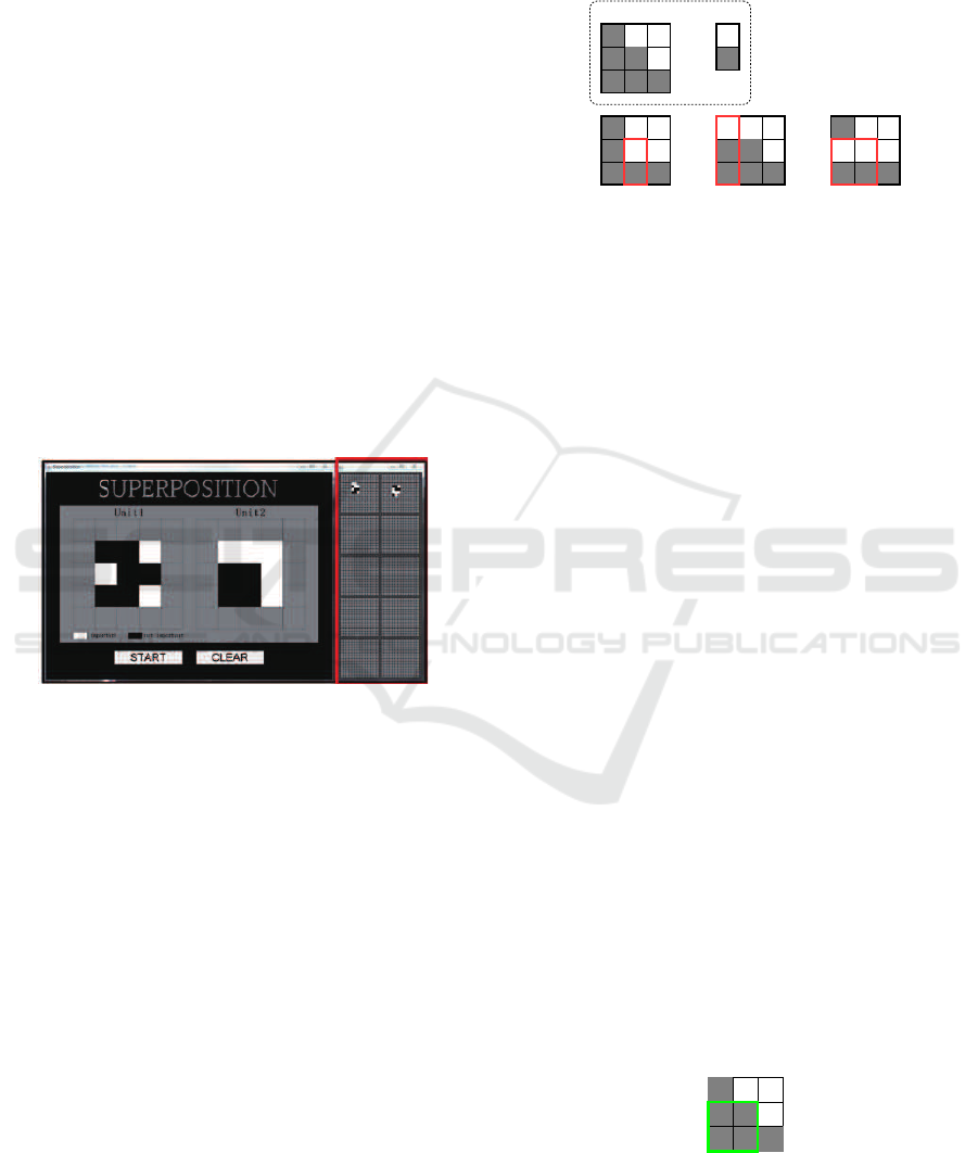
3.5 Implementation
We implemented a system based on this method in
Java (Figure 9). The system initially shows a field
consisting of 5∗ 5 cells for each rectangle by default.
A user inputs patterns of pairs of black and white rect-
angular tiles, and then the system makes a unit and
solves the problem. All quantitative optimal solutions
that are found are displayed, and if a user selects one
of them, the resizing and moving processes of the su-
perposition are shown as an animation, which pro-
vides a visual aid to help the user’s understanding.
Figure 9: A screen shot of the system.
4 SYSTEM EXTENSION
4.1 Maximal Black Rectangle
A unit produced by a tiling approach represents a con-
figuration; that is, a set of topological relationships
between black and white regions. A superposition is
defined as the manner in which we place a tile onto
another tile. Each tile corresponds to a subregion of
an original target object, and the exact size is ignored
when creating a unit. This implies that there may be
another solution whereby a greater number of tiles are
covered if we admit superposing one tile onto more
than one other tile.
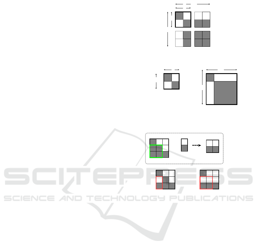
For example, in Figure 10, when superposing U
f
onto U
b
, (a) is the quantitative optimal solution when
superposing one tile onto a single tile, whereas (b)
and (c) show the solutions if allowed to place a tile
onto multiple tiles. In these cases, we have a larger
number of covered tiles. Such a phenomenon occurs
when the granularity of two units differ, and indicates
that we must take into account such qualitative factors
in merging two representations.
Ub Uf
(a) (b) (c)
Figure 10: Superpositions of two units with different gran-
ularity.
To this end, we extend the representation of a unit
while preserving the condition whereby we place a
single tile onto another single tile. We fix a back-
ground unit and extend only a foreground unit, since
the number of the black tiles is used as an evaluation
measure. A maximal black rectangle, corresponding
to the limit of the extension of the background unit, is
determined. Intuitively, a maximal black rectangle is
the connected set of black tiles of which the shape is
a rectangle.
Definition 4.1 (Maximal Black Rectangle). Let T be
a set of tiles of a unit with granularity r ∗ c. A black
rectangle R(x, y, r
′
, c
′
) included in the unit where 0 ≤
x < r− r
′
, 0 ≤ y < c− c
′
is defined as follows:
R(x, y, r
′
, c
′
) =
{t
ij
| t
ij
∈ B (T), x ≤ i < x+ r
′
, y ≤ j < y+ c
′
}.
R(x, y, r
′
, c
′
) is called a maximal black rectangle of
the unit, if none of the following conditions are satis-
fied:
1. y 6= 0 and ∀t
ij
; x≤ i < x+r
′
, j = y− 1, t
ij
∈ B (T).
2. y 6= c− c
′
and ∀t
ij
; x ≤ i < x+ r
′
, j = y+ c
′
, t
ij
∈
B(T).
3. x 6= 0 and ∀t
ij
; i = x−1, y ≤ j < y+ c
′
, t
ij
∈ B (T).
4. x 6= r − r
′
and ∀t
ij
; i = x + r
′
, y ≤ j < y+ c
′
, t
ij
∈
B(T).
r
′
∗ c
′
is called its granularity.
For example, for a unit in Figure 11, one of
the maximal black rectangles is highlighted with the
green frame.
Figure 11: A maximal black rectangle.
ICAART 2017 - 9th International Conference on Agents and Artificial Intelligence
428
4.2 Extension of a Unit
Assume that U
b
is more granular than U
f
. If there ex-
ists a maximal black rectangle of U
b
in which the cov-
ered tiles in a quantitative optimal solution are prop-
erly included, then an extension of U
f
is performed
to the extent of the maximal black rectangle. The ex-
tended unit is qualitatively equivalent to the original
unit.
Let U
f
be a unit with granularity r ∗ c, and let
R(x, y, r
′
, c
′
) be a maximal black rectangle of U
b
. An
extension of U
f
, denoted by U
′
f
, is a unit with granu-
larity r
′
∗c
′
, and attributes (black/white) of its tiles are
defined as follows:
Let T and T
′
be sets of tiles of U
f
and U
′
f
, respec-
tively.
• t
′
ij
∈ B(T
′
) iff
t
ij
∈ B(T) (0 ≤ i < r, 0 ≤ j < c)
t
i c−1
∈ B (T) (0 ≤ i < r, c ≤ j < c
′
)
t
r−1 j
∈ B(T) (r ≤ i < r
′
, 0 ≤ j < c)
t
r−1 c−1
∈ B(T) (r ≤ i < r
′
, c ≤ j < c
′
)
• t
′
ij
∈ W (T
′
) otherwise.
It is the number of tiles and not the attribute of
tiles of U
f
that affects the number of covered tiles.
Therefore, we are not concerned about the attributes
of added tiles but hold thatU
f
andU
′
f
are qualitatively
equivalent. Here, with vertical extension, the tiles in
new rows have the same attributes as those in the last
row of the original matrix, and those with horizontal
extension are defined similarly.
Figure 12(a) shows an example of an extension
from unit U
f
, with granularity 2 ∗ 2 (Figure 12(b)) to
U
′
f
and with granularity 4∗ 4 (Figure 12(c)). Note that
U
f
and U
′
f
are qualitatively equivalent, but quantita-
tively different.
Definition 4.2 (Qualitative Solution). Let U
′
f
be an
extension of U
f
. A solution for superposing U
′
f
on U
b
is called a qualitative solution for the superposition of
U
f
on U
b
.
For example, consider the superposition of U
f
onto U
b
shown in Figure 13. A maximal black rect-
angle of U
b
is highlighted as the green frame. Fig-
ure 13(a) shows a quantitative optimal solution for a
superposition of U
f
on U
b
, and Figure 13(b) is a qual-
itative solution for a superposition of U
f
on U
b
.
4.3 Properties
The following properties immediately hold from the
definition of extension of a unit and the completeness
of the superposition algorithm shown in section 3.2.
r
c
r’
(b)Uf (c)Uf’
c’
c’
c
r
r’
(a)extention of a unit
Figure 12: Definition of extension of a unit.
extend
Ub Uf
(a)superposition of
Uf on Ub
Uf’
(b)superposition of
Uf’ on Ub
Figure 13: (a) Quantitative solution and (b) qualitative so-
lution.
Proposition 4.1. For a superposition of a unit U
f
on U
b
, if all covered tiles for the quantitative opti-
mal solution are properly included in some maximal
black rectangle, then a qualitative solution in which
the number of covered tiles is the granularity of the
maximal black rectangle can be obtained.
Proposition 4.2. If no quantitative solution exists for
a superposition of U
f
on U
b
, then there is no qualita-
tive solution for a superposition of U
f
on U
b
.
5 CONCLUSION
We have described a qualitative treatment of two-
dimensional superposed objects consisting of should-
be-visible parts and may-be-hidden parts. We con-
sider this as the problem of superposing rectangles
while maintaining some pre-specified parts visible.
Our approach is as follows. First, we qualify an
object to make a least refined model and represent it
Superposition of Qualitative Rectangles using a Quantitative Model
429

in matrix form. We find a solution with a quantitative
computation using the matrix, then search for a better
solution considering a qualitatively equivalent model
of the object.
The main contributions of this work are as fol-
lows:
• We presented a sound and complete algorithm to
provide quantitativesolutions, and implemented it
as a system with a graphical user interface.
• We extended the algorithm so that a qualitative so-
lution can be obtained when the granularities of
units differ.
The method described is useful for analyzing or
designing a projection of three-dimensional objects.
An evaluation measure on the obtained solutions
is determined based on the user’s purpose. When su-
perposing more than two units, the black tiles that are
not hidden provide room for a third unit to be placed.
Therefore, it is not always true that fewer covered tiles
offer a better solution. The location of a black tile of
a resulting figure is also an evaluation measure candi-
date.
As part of future work, we plan to evaluate the
obtained solutions to handle superpositions of more
than two units.
REFERENCES
Birgin, G., Lobato, R. D., and Morabito, R. (2010). An
effective recursive partitioning approach for the pack-
ing of identical rectangles in a rectangle. Journal of
the Operational Research Society, 61:306–320.
Chen, J., Cohn, A., Liu, D., Wang, S., Ouyang, J., and
Yu, Q. (2013). A survey of qualitative spatial rep-
resentations. The Knowledge Engineering Review,
30(1):106–136.
Cohn, A. G. and Hazarika, S. M. (2001). Qualitative spatial
representation and reasoning: An overview. Funda-
mental Informaticae, 46(1-1):1–29.
Cohn, A. G. and Renz, J. (2007). Handbook of Knowledge
Representation, chapter 13. Qualitative Spatial Rea-
soning, pages 551–596. Elsevier.
Freeman, H. (1991). Geographical Information Systems,
chapter Computer name placement, pages 449–460.
John Wiley.
Ghourabi, F. and Takahashi, K. (2015a). Formalizing the
qualitative superposition of rectangles in proof assis-
tant Isabelle/HOL. In Seventh International Confer-
ence on Agents and Artificial Intelligence, pages 530–
539.
Ghourabi, F. and Takahashi, K. (2015b). Generalization
of superposition of rectangles based on direction re-
lations. In The 28th International Workshop on Qual-
itative Reasoning.
Goyal, R. K. and Egenhofer, M. J. (2001). Similarity of
cardinal directions. In Proceedings of the Advances
in Spatial and Temporal Databases, 7th International
Symposium, SSTD 2001, pages 36–58.
Konishi, T. and Takahashi, K. (2012). Superposition of
rectangles with visibility requirement: A qualitative
approach. International Journal on Advances in Soft-
ware, 4(3&4):422–433.
Lapaugh, A. S. (1996). Layout algorithm for VLSI design.
ACM Computing Surveys, 28(1):59–61.
Li, J., Plaisant, C., and Shneriderman, B. (1998). Data ob-
ject and label placement for information abundant vi-
sualizations. In Proceedings of the Workshop of New
Paradigms Information Visualization and Manipula-
tion, pages 41–48.
Li, S. and Liu, W. (2015). Cardinal directions: A compari-
son of direction relation matrix and objects interaction
matrix. International Journal of Geographical Infor-
mation Science, 29(2):194–216.
Lodi, A., Martello, S., and Monaci, M. (2002). Two-
dimensional packing problems: a survey. European
Journal of Operational Research, (141):242–252.
Randell, D., Witkowski, M., and Shanahan, M. (2001).
From images to bodies: Modelling and exploiting spa-
tial occlusion and motion parallax. In Proceedings of
Seventeenth International Joint Conference on Artifi-
cial Intelligence, pages 57–66.
Renz, J. and Mitra, D. (2004). Qualitative direction calculi
with arbitrary granularity. In PRICAI 2004: Trends in
Artificial Intelligence, pages 65–74.
Skiadopoulos, S. and Koubarakis, M. (2005). On the con-
sistency of cardinal direction constraints. Artificial In-
telligence, 163(1):91–135.
Stock, O. (1997). Spatial and Temporal Reasoning. Kluwer
Academic Press.
ICAART 2017 - 9th International Conference on Agents and Artificial Intelligence
430
