
High Order Diffraction Suppression of the Membrane with Hexagonal
Hole Array
Ziwei Liu
1,2,3
, Lina Shi
1,2
, Tanchao Pu
1,2,3
, Changqing Xie
1,2
, Hailiang Li
1,2
and Jiebin Niu
1,2
1
Key Laboratory of Microelectronic Devices & Integrated Technology,
Institute of Microelectronics of Chinese Academy of Sciences, Beijing 100029, China
2
Jiangsu National Synergetic Innovation Center for Advanced Materials, Nanjing 210009, China
3
University of Chinese Academy of Sciences, Beijing 101408, China
Keywords:
Diffraction Gratings, Binary Optics, Optical Design Fabrication, Spectroscopy, High-Resolution.
Abstract:
We propose the array of hexagonal holes with the completely suppression of the 2nd, 3rd, and 4th order diffrac-
tions. The membrane with holes can be free-standing and scalable from X-rays to far infrared wavelengths.
We numerically and experimentally demonstrate that the 2nd, 3rd and 4th order diffractions near the 1st or-
der diffraction are completely suppressed. The hexagonal hole with some size results in a desired diffraction
pattern. Our results should be of great interest in a wide spectrum unscrambling for any wavelength range.
1 INTRODUCTION
Diffraction gratings are optical components with a pe-
riodic structure, which disperse different wavelengths
of light into its constituent spectrum. They play a
crucial role in modern optical science, especially in
extreme-ultraviolet and soft x-ray regions. Over a pe-
riod of several decades, the applications of diffraction
gratings are extensively used in astrophysical plasma
diagnosis and synchrotron radiation light monochro-
mator (K. P. Beuermann, 1998; Y. Saitoh, 2000).
Normally, conventional diffraction gratings are used
as dispersion elements in spectral measurement, the
diffracted beams corresponding to consecutive orders
may overlap, depending on the spectral content of
the incident beam and the grating density (V. Da-
neu, 2000; I. Shoshan, 1977). The higher the spec-
tral order, the greater the overlap into the next order
(V. Daneu, 2000; I. Shoshan, 1977; K. Yamane, 2003;
Y. W. Huang, 2004). However, in many applications,
only the first order is meaningful and necessary. The
data obtained with this grating due to the high-order
diffraction contamination will decrease the accuracy
of spectral data. The single-order diffractions with
accurate spectroscopic data have been the major con-
cern.
Sinusoidal amplitude transmission grat-
ings(STGs) can suppress the high-order diffraction
efficiently which have only 0th- and ±1
st
order
diffractions in a visible light region, but it’s hard
to extend to x-ray region. Due to the all known
materials in the extreme ultraviolet and x-ray regions
have complex refractive index and are very close to
unity. The fabrication with high line density grating is
difficult to achieve according today’s nanofabrication
technology. In recent years, many new gratings
which have quasi-sinusoidal transmission functions
have been designed to solve this problem, but still
limited to the modern photolithography technology,
especially for applications in the extreme-ultraviolet
and x-ray regions. The pattern structure of the
gratings is recognized by many as the key to suppress
high-order diffraction effectively and decrease the
difficulty of fabrication.
In this Letter, we introduce a novel design of
single-order diffraction which can suppress high-
order diffraction significantly as sinusoidal amplitude
gratings do. The key idea is to make the hexago-
nal holes follow the rectangle array, leading to dom-
inant ±1
st
diffraction orders on the observation line
(M. Born, 1997; L. Cao, 2007; L. Kuang, 2010;
M. E. Warren, 1995; G. Vincent, 2008). Compared
with the previous schemes, the single-order diffrac-
tion grating with binary transmittance value of 0
and 1 based on this kind of transmission function
(F. J. Torcal-Milla, 2008; C. Xie, 2010; C. Xie, 2012),
which is larger than the value of 6.25% for ideal si-
nusoidal amplitude grating. This new type of single
optical element with the capabilities of quasi-single
order diffraction named hexagonal aperture gratings
Liu Z., Shi L., Pu T., Xie C., Li H. and Niu J.
High Order Diffraction Suppression of the Membrane with Hexagonal Hole Array.
DOI: 10.5220/0006103400590064
In Proceedings of the 5th International Conference on Photonics, Optics and Laser Technology (PHOTOPTICS 2017), pages 59-64
ISBN: 978-989-758-223-3
Copyright
c
2017 by SCITEPRESS – Science and Technology Publications, Lda. All rights reserved
59
(HAGs) as shown in Figure 1, consists of a series
of periodically arranged hexagonal apertures. Such
structure has great advantages in extreme-ultraviolet
and x-ray regions. In addition, HAGs on the glass
substrate are easy to fabricate. Both numerical solu-
tion and experimental results demonstrate the diffrac-
tion efficiency of the HAGs. It offers a new idea of
single-order diffraction and benefit in fabrication.
2 DESIGN AND SIMULATIONS
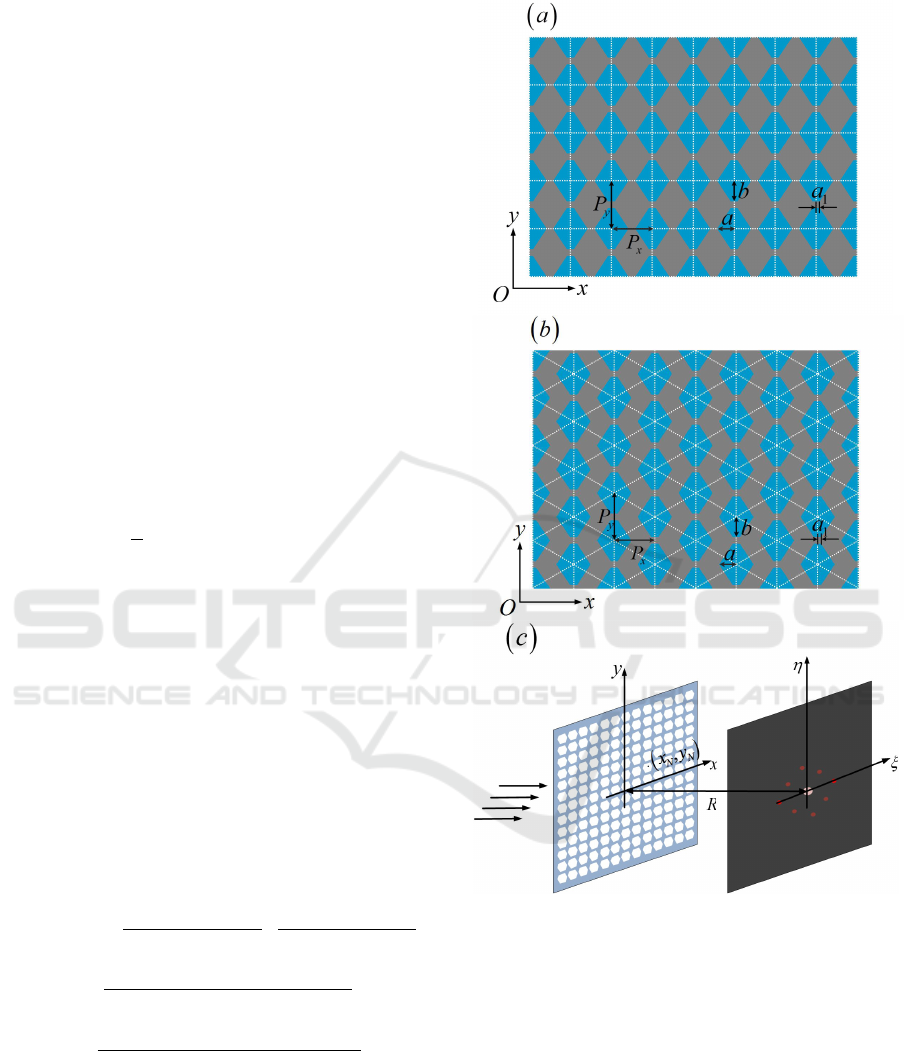
We start the design from the array of hexagonal holes
as shown in Figure 1. The (x,y) and (η,ξ) are the
coordinate systems in the hole plane and diffraction
plane respectively. For a membrane that contains a
large number of identical and similarly oriented holes,
the light distribution in the Fraunhofer diffraction pat-
tern is given by (W. Goodman, 1996),
U(p,q) = C
∑
N
e
−ik(px
n
+qy
n
)
ZZ
A
e
−ik(px
0
+qy
0
)
dx
0
dy
0
(1)
Here C =
√
P/(λR), P is the power density inci-
dent on the hole array, λ is the incident light wave-
length, R is the distance between the hole array plane
and the diffraction plane. The coordinates of the hole
center are (x
1
,y
1
),(x
2
,y
2
),.. . (x
N
,y
N
), and k is the
wave vector. The integration extends over the hole
area and the integral expresses the effect of a single
hole. The sum represents the superposition of the co-
herent diffraction patterns.
For the square array of N
x
N
y
hexagonal holes of
the side 2a
1
along the x axis, the diagonal 2a along
the y axis, and the height along axis as shown in Fig.
1(a), the diffraction intensity pattern is
I(p,q) = U (p, q) ∗U
∗
(p,q)
= I
0
·
sin
2
(N
x
kpP
x
/2)
N
2
x
·sin
2
(kpP
x
/2)
·
sin
2
(N
y
kqP
y
/2)
N
2
y
·sin
2
(kqP
y
/2)
·
cos(kpa
1
−kqb) −cos kpa
kp(a + a
1
) ·(kp(a −a
1
) + kqb)
+
coskpa −cos(kpa
1
+ kqb)
kp(a + a
1
) ·(−kp(a −a
1
) + kqb)
2
(2)
Here I
0
= C
2
· (N
x
N
y
· 2(a + a
1
)b)
2
is the peak
irradiance of the diffraction pattern. For simplicity,
here we set I
0
= 1,P
x
and P
y
(shown in Fig. 1) are
respectively the periods along the x and y axes.
Figure 1: The array of hexagonal holes. The side along
the x axis is 2a
1
, the diagonal along the x axis is 2a and
the height along the y axis is 2b. (a) The square array with
periods P
x
and P
y
. (b) The triangle array with periods 2P
x
and P
y
. (c) The coordinate systems in the aperture plane and
observation planes.
Similarly, for the triangle array as shown in Fig.
1(b), the diffraction intensity pattern is
PHOTOPTICS 2017 - 5th International Conference on Photonics, Optics and Laser Technology
60
I(p,q) = U(p,q) ∗U
∗
(p,q)
= I
0
·
sin
2
(N
x
/2 ·kp2P
x
/2)
(N
x
/2)
2
·sin
2
(kp2P
x
/2)
·
sin
2
(N
y
kqP
y
/2)
N
2
y
·sin
2
(kqP
y
/2)
· cos
2
(kp2P
x
/4 + kqP
y
/4)
·
cos(kpa
1
−kpb) −coskpa
kp(a + a
1
) ·(kp(a −a
1
) + kqb)
+
coskpa −cos(kpa
1
+ kqb)
kp(a + a
1
) ·(−kp(a −a
1
) + kqb)
2
(3)
The parameters are same as the square array except
the period 2P
x
along the x axis.
Here, we focus on the diffraction intensity along
the x axis since spectral measurement is usually at
one direction. For the square and triangle arrays, the
diffraction intensity according to Eq.(2) and (3) along
the x axis are both given by
I(p) = I
0
·
sin
2
(N
x
kpP
x
/2)
N
2
x
·sin
2
(kpP
x
/2)
·
sin(kp(a + a
1
)/2 ·sin(kp(a −a
1
)/2)
kp(a + a
1
)/2 ·kp(a −a
1
)/2
2
(4)
And thus the m-th order diffraction along the x
axis is
I(m)=I
0
·
sin(m(a + a
1
)π/P
x
)·sin(m(a −a
1
)π/P
x
)
m(a + a
1
)/2·m(a −a
1
)π/P
x
2
(5)
In real spectral measurement, only the near diffrac-
tions (such as the 2
nd
, 3
rd
and 4
th
order diffractions)
will overlap the 1st order diffraction. The far diffrac-
tions are usually very small and have little effects on
the 1
st
order diffraction. Thus we will consider the
structure parameters which lead to the zeros of the
2
nd
, 3
rd
and 4
th
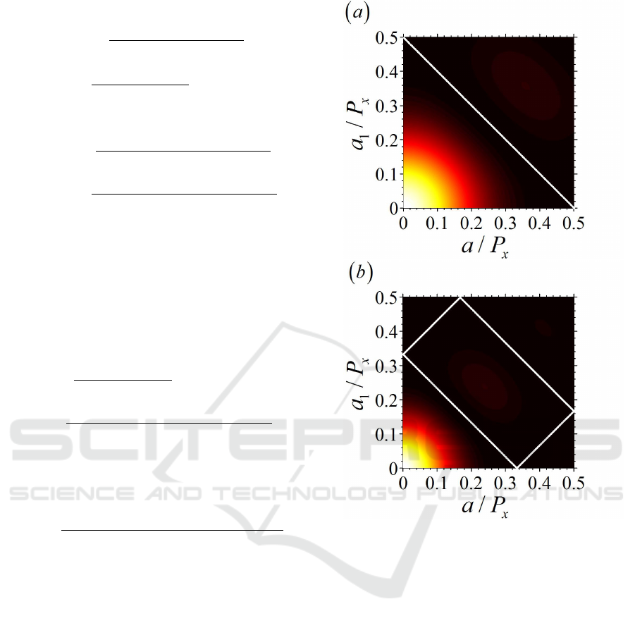
order diffractions. Equation (4) shows
that the diffractions along the x axis have nothing to
do with the parameters of b and P
y
. The diffractions
along the x axis depend on the parameters of a, a
1
and
P
x
as shown in Fig.2.
According to Equation (5) and Fig.2,the 2
nd
, 3
rd
and 4
th
order diffractions I(2) = I(3) = I(4) = 0 as
a
1
= P
x
/12 and a = 5P
x
/12. At the same time, the 5
th
order diffraction I(5) = 0.0004435I
0
= 0.0016I(1),
the 0
th
order diffraction I(0) = I
0
, the 1
st
order
diffraction I(1) = 0.2772I
0
.
Figure 3 presents the diffraction intensity pat-
tern the array of hexagonal holes with a
1
= P
x
/12,
Figure 2: (a) The dependent relation of the 2
nd
order
diffraction on a,a
1
and P
x
. The white line denotes the 2
nd
order diffraction is zero. (b) The dependent relation of the
3
rd
order diffraction on a,a
1
and P
x
. The white line denotes
the 3
rd
order diffraction is zero.
a = 5P
x
/12 and b = P
x
/12 according to Eq.(2) and
(3). Comparing with the diffraction pattern of con-
ventional 1:1 traditional gratings(TGs), higher-order
diffraction components of HAGs are suppressed by
about three orders, which is weak enough for appli-
cation and very similar to the ideal sinusoidal trans-
mission gratings. As expected, the 0
th
and 1
st
order
diffractions are kept along x axis, and the 2
nd
, 3
rd
and
4
th
diffractions disappear. The logarithm of diffrac-
tion intensity along x axis in Fig.3(c) and (d) presents
clearly the complete suppression of the 2
nd
, 3
rd
and
4
th
order diffractions. The 5
th
order diffraction is
smaller than the noise between the 0
th
and 1
st
order
diffractions. Insets in Fig. 3 shows clearly intensity
distributions of the 0
th
and 1
st
order diffractions. Fig-
ure 3 shows that the high order diffractions along axis
High Order Diffraction Suppression of the Membrane with Hexagonal Hole Array
61
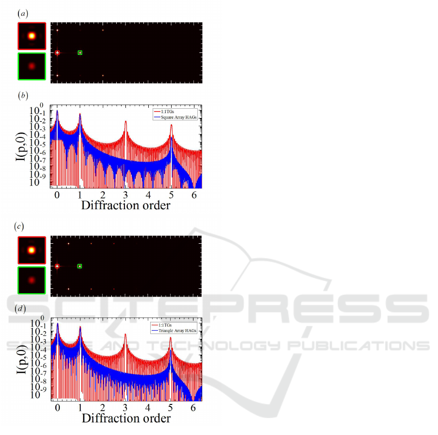
Figure 3: The far-field diffraction intensity pattern of the
hexagonal hole array. The diffraction intensity along the x
axis. Insets: the 0
th
and 1
st
order diffractions. (a)(b) For the
square array. (c)(d) For the triangle array. (e)(f) The typical
diffraction patterns by 1:1 TGs.
are effectively suppressed by the array of hexagonal
holes.
Figure 3 also presents important figures of merit
of the HAGs, the relative diffraction efficiency of the
±1
st
orders (the +1
st
or −1
st
order diffracted light
intensity divided by the 0
th
order diffracted light in-
tensity) is 27.16%. For the triangle array, the relative
diffraction efficiency of the ±1
st
orders are 27.13%.
For the HAGs, the smallest feature size in both of
the arrays is 4µm, making it much easier to fabri-
cate, compared with sinusoidal amplitude transmis-
sion gratings designed previously. In addition, the gap
between the apertures is flexible for the practical ap-
plications, which have not effect on the result.
3 EXPERIMENTAL RESULTS
AND DISCUSSION
A proof-of-principle experiment is performed to con-
firm our theoretical and numerical results. The
square array of hexagonal holes with 4cm × 4cm
area is fabricated on a glass substrate by DESIGN
WRITE LAZER 2000 from Heidelberg Instruments
Mikrotechnik GmbH. The microphotograph of fabri-
cated structure is illustrated in Fig.4(a) and (b). Pe-
riods P
x
and P
y
of the quasi-rectangle array along the
x and y axes are respectively 24µm and 28µm. The
structure consists of 1500 ×1500 holes. The entirety
experimental setup for optical demonstration is shown
in Fig.4(c). A collimated laser beam from Sprout
(Lighthouse Photonics) with wavelength of 632nm
was used to illuminate the fabricated the hexagonal
hole array, and the far-field diffraction pattern from
the gratings was focused by a lens and then recorded
on a charge coupled device (CCD) camera (ANDOR
DU920P-BU2) with 1612 ×1214 pixels and 4.4µm
pixel size was placed in the far field to record the
diffraction patterns.
The measurement results are shown in Fig.5. As
expected, the higher-order contributions of the fabri-
cated HAGs are significantly suppressed. The inte-
grated diffraction intensity of the diffraction orders
along the ξ axis is shown in Fig.5(b). The relative
diffraction efficiency is an important parameter for
describing the characteristics of the HAGs. For per-
fect HAGs, it agrees well with the theoretical value,
the higher-order diffraction components are signifi-
cantly suppressed, which is only about 0.6% of the
±1
st
order in amplitude. It is obvious that only 0
th
and ±1
st
orders exist along the ξ axis, which is agrees
well with the numerical simulation and the optimal
case to suppress higher order diffraction is achieved.
The relative diffraction efficiencies of the square ar-
ray of the 1
st
order is 30.27%. For the triangle array,
the +1
st
order is 25.82%, respectively. The experi-
mental result differs slightly from the ideal intensity
distribution shown in Fig.3. This may be attributed
to the limited dynamic range and signal-to-noise ra-
tio of the CCD, filter inhomogeneity, slightly tilted
installation of the measured HAGs and the inevitable
imperfection of the fabrication. Nevertheless, the ex-
perimental results clearly verify that the HAGs with
quasi suppression of higher-order diffractions are su-
perior to a conventional transmission grating.
PHOTOPTICS 2017 - 5th International Conference on Photonics, Optics and Laser Technology
62
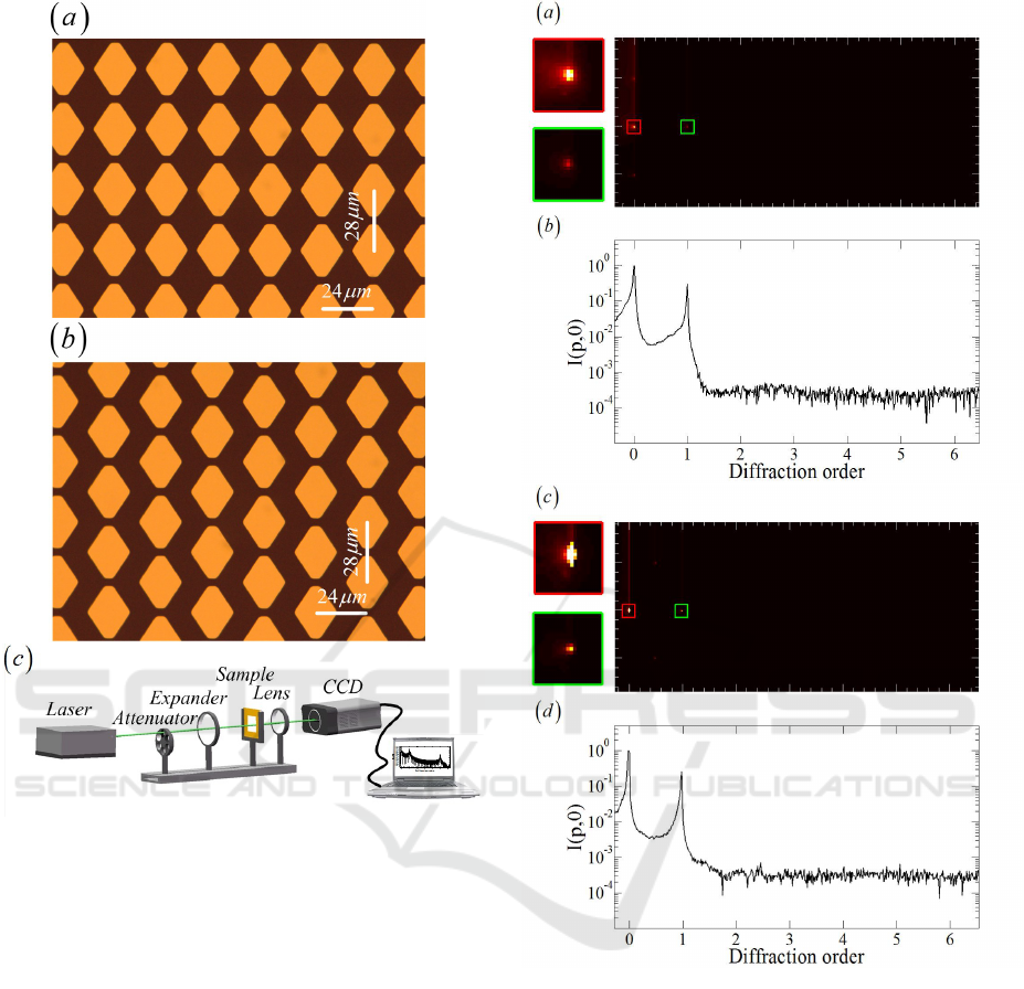
Figure 4: (a) The schematic illustration of HAGs. (b) Mi-
crophotograph of the fabricated quasi-rectangle array with
4cm×4cm area. (c) Experimental setup for the optical mea-
surement.
4 CONCLUSIONS
In conclusion, the binary structure with hexagonal
hole array has been proposed to suppress the high-
order diffractions which may lead to wavelength over-
lapping in spectral measurement. We obtian the rel-
ative diffraction efficiency 27.72% of the first order
diffraction, which is higher than 25% of the first or-
der diffraction for ideal sine grating. The membrane
with holes can be free-standing and scalable from
X-rays to far infrared wavelengths. Both numeri-
cal and experimental results have demonstrated the
2
nd
, 3
rd
and 4
th
order diffractions are completely sup-
pressed. The binary hole array offers an opportunity
for high-accuracy spectral measurement and will pos-
sess broad potential applications in optical science
and engineering fields.
Figure 5: (a) (c)The far-field diffraction intensity pattern
of the quasi-triangle array of rectangular holes. (b) (d)The
diffraction intensity along the x axis.
ACKNOWLEDGEMENTS
We thank Yongliang Zhang for the valuable discus-
sion. We thank the Optics Laboratory for the use of
their equipment.
REFERENCES
C. Xie, X. Zhu, H. (2012). Toward two-dimensional
nanometer resolution hard X-ray differential-
High Order Diffraction Suppression of the Membrane with Hexagonal Hole Array
63

interference-contrast imaging using modified photon
sieves. Opt. Lett. 37, 749-751.
C. Xie, X. Zhu, L. S. (2010). Spiral photon sieves apodized
by digital prolate spheroidal window for the genera-
tion of hard-x-ray vortex. Opt. Lett. 35, 1765-1767.
F.J. Torcal-Milla, L. M. Sanchez-Brea, E. B. (2008).
Diffraction of gratings with rough edges. Opt. Express
16, 19757.
G.Vincent, R. Haidar, S. C. (2008). Realization of si-
nusoidal transmittance with subwavelength metallic
structures. J. Opt. Soc. Am. B 25, 834.
I. Shoshan, N. N. Danon, U. P. O. (1977). Performance
of a very high resolution soft x-ray beamline BL25SU
with a twin-helical undulator at SPring-8. Rev.
Sci.Instrum. 71, 3254.
K. P. Beuermann, R. Lenzen, H. B. (1998). Properties of a
transmission grating behind a grazing incidence tele-
scope for cosmic x-ray spectroscopy. Appl. Opt.16,
1425.
K. Yamane, Z. Zhang, K. O. (2003). Optical pulse com-
pression to 3.4fs in the monocycle region by feedback
phase compensation. Opt. Lett. 28, 2258.
L. Cao, E. Frster, A. F. (2007). Single order x-ray diffraction
with binary sinusoidal transmission grating. Appl.
Phys. Lett. 90 053501.
L. Kuang, C. Wang, Z. W. (2010). Quantum-dot-array
diffraction grating with single order diffraction prop-
erty for soft x-ray region. Rev. Sci. Instrum. 81,
073508.
M. Born, E. W. (1997). Principles of Optics. Cambridge U.
Press, 7th ed.(expanded) edition.
M. E.Warren, R. E. Smith, G. A. V. (1995). High-efficiency
subwavelength diffractive optical element in GaAs for
975 nm. Opt. Lett. 20, 1441.
V. Daneu, A. Sanchez, T. Y. F. (2000). Narrowband oper-
ation of a pulsed dye laser without intracavity beam
expansion. J. Appl.Phys. 48, 4495.
W. Goodman, J. (1996). Introduction to Fourier Optics.
McGraw-Hill, 2nd edition.
Y. Saitoh, H. Kimura, Y. S. (2000). Performance of a very
high resolution soft x-ray beamline BL25SU with a
twin-helical undulator at SPring-8. Rev. Sci.Instrum.
71, 3254.
Y. W. Huang, S. T. Hu, S. Y. Y. (2004). Tunable diffrac-
tion of magnetic fluid films and its potential applica-
tion in coarse wavelength-division multiplexing. Opt.
Lett.29, 1867.
PHOTOPTICS 2017 - 5th International Conference on Photonics, Optics and Laser Technology
64
