
User Calibration-free Method using Corneal Surface Image
for Eye Tracking
Sara Suda
1
, Kenta Yamagishi
2
and Kentaro Takemura
1,2
1
Graduate School of Engineering, Tokai University, Hiratsuka, Japan
2
Department of Applied Computer Engineering, Tokai University, Hiratsuka, Japan
Keywords:
User Calibration-free, Corneal Surface Image, 3D Eye Model.
Abstract:
Various calibration methods to determine the point-of-regard have been proposed for eye tracking. Although
user calibration can be performed for experiments carried out in the laboratory, it is unsuitable when apply-
ing an eye-tracker in user interfaces and in public displays. Therefore, we propose a novel calibration-free
approach for users that is based on the use of the corneal surface image. As the environmental information is
reflected on the corneal surface, we extracted the unwarped image around the point-of-regard from the cornea.
The point-of-regard is estimated on the screen by using the unwarped image, and the regression formula is
solved using these points without user calibration. We implemented the framework of the algorithm, and we
confirmed the feasibility of the proposed method through experiments.
1 INTRODUCTION
In recent years, eye-tracking technology has im-
proved to a remarkable extent; thus, the future use
of an eye-tracker for applications such as market-
ing and user interfaces can be expected. Various ap-
proaches have been proposed for estimating the point-
of-regard, and the eye-tracking method can roughly
be classified into two types. The conventional method
involves an approach based on regression, in which
the point-of-regard is calculated using the Purkinje
point and the center of the pupil. In contrast, the
visual axis is calculated for estimating the point-of-
regard when we employ the model-based approach.
Both of these methods require user calibration to be
performed before determining the point-of-regard,but
the calibration is a cumbersome process for the user.
Therefore, calibration-free methods have been
studied actively. Nagamatsu et al.(Nagamatsu et al.,
2009) developed a user calibration-free method for
calculating the two visual axes using the optical axes
of both eyes. The point-of-regard is estimated us-
ing the two visual axes on the display plane, and
high accuracy was achieved. However, it needs the
location of display and camera as hardware calibra-
tion. Additionally, Sugano et al.(Sugano and Bulling,
2015) proposed user calibration-free gaze tracking us-
ing a saliency map, whereby calibration is achieved
automatically when the user looks at the scene for
a while. In fully automatic calibration, gaze can be
estimated around 10 degrees without user-calibration
and hardware calibration. Khamis et al.(Khamis et al.,
2016) proposed an implicit calibration that correlates
users’ eye movements with moving on-screen targets
while the user is simply reading this text. We also
started to study a calibration-free method for users
based on this background, but our motivation is to
achieve the calibration without the geometrical re-
striction, and the point-of-regardis estimated immedi-
ately. Our aim is to solve these problems by focusing
on the corneal-imaging technique(Nishino and Na-
yar, 2006). This technique acquires the environmen-
tal information from the reflection of the surface of
the cornea. Nitschke et al.(Nitschke and Nakazawa,
2012) proposed to obtain a high-resolution image by
super-resolution, and Wang et al.(Wang et al., 2005)
succeeded in removing the texture of the iris from
the image. Additionally, Takemura et al.(Takemura
et al., 2014) the method for estimating the focused ob-
ject using corneal-imaging technique. Therefore, we
expect the corneal-imaging technique to be a break-
through for solving the calibration problem, and we
propose a calibration-free method for users for eye
tracking using the corneal surface image.
The remainder of this paper is organized as follows.
First, the 3D eye model is introduced in section 2,
after which model-based iris tracking is described in
section 3. Then, a method for generating the un-
Suda S., Yamagishi K. and Takemura K.
User Calibration-free Method using Corneal Surface Image for Eye Tracking.
DOI: 10.5220/0006100100670073
In Proceedings of the 12th International Joint Conference on Computer Vision, Imaging and Computer Graphics Theory and Applications (VISIGRAPP 2017), pages 67-73
ISBN: 978-989-758-227-1
Copyright
c
2017 by SCITEPRESS – Science and Technology Publications, Lda. All rights reserved
67
warped image from the corneal surface image is ex-
plained in section 4. A method that is calibration-free
for users is proposed, and we confirm the feasibility
of the method in section 5 and 6, respectively. Fi-
nally, section 7 presents our conclusions and our fu-
ture work.
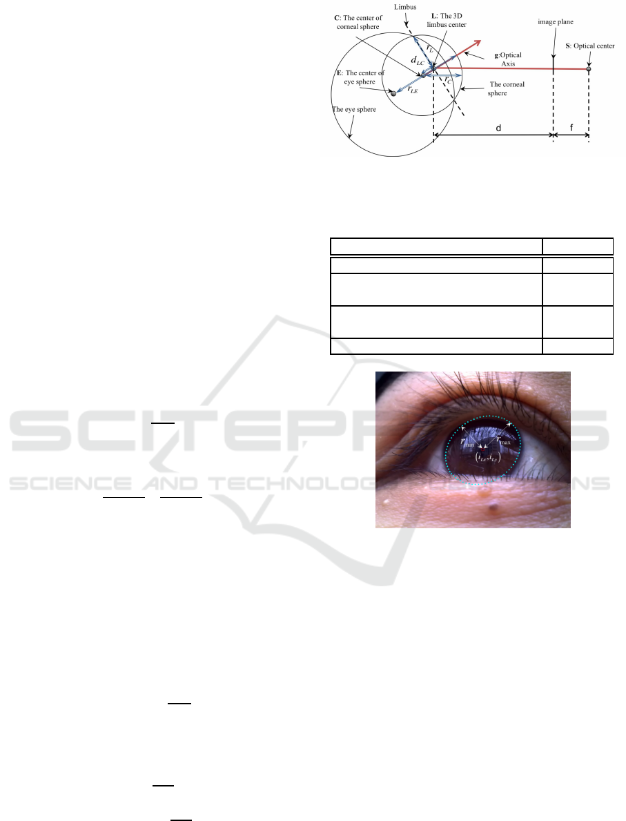
2 GENERATING THE 3D EYE
MODEL
A 3D model of the eye is used for tracking the iris and
extracting the corneal surface image. This model con-
sists of the corneal sphere and the eyeball as shown in
Figure 1, and four anatomical parameters are defined
as in Table 1. The position of the 3D eye is deter-
mined by the size of the iris; therefore, the area of
the iris is detected using an elliptical approximation
as shown in Figure 2. The radii of the major and mi-
nor axes of the iris area are r
max
and r
min
, respectively,
and (i
Lx
, i
Ly
) is the center of the iris. When the edges
of the iris area are selected as the initial stage, the 3D
eye model is generated by the following equations.
The distance d from the image plane to the 3D limbus
center is defined by
d = f
r
L
r
max
, (1)
and the 3D limbus center L is determined by the fol-
lowing equation:
L =
d
i
Lx
− cx
f
, d
i
Ly
− cy
f
, d
T
, (2)
where (cx, cy) and f are the center of the image and
the focal length, respectively. The 3D limbus is the
intersection of the eyeball and the corneal sphere, and
it is the border of the iris. The optical vector g is esti-
mated based on the 3D limbus center by the following
equation:
g = [sin(τ)sin(φ), −sin(τ)cos(φ), −cos(τ)]
T
, (3)
where φ is the rotation of the limbus ellipse, and τ is
the tilt of the iris on the 3D eye model and is computed
by
τ = ±cos
−1
r
min
r
max
. (4)
The center of the corneal sphere C and the center of
the eyeball E are defined by the two following equa-
tions, respectively:
C = −d
LC
g
kgk
+ L, (5)
E = −(r
LE
− r
C
)
g
kgk
+ C. (6)
Finally, the position of the 3D eye model is computed
as shown in Figure 3.
Figure 1: Geometric 3D eye model consisting of the eye
sphere and the corneal sphere.
Table 1: Parameters of the eyeball model as defined by
anatomical data.
Eyeball parameters Size[mm]
Radius of corneal sphere(r
C
) 7.78
Distance between corneal surface
and eyeball center(r
LE
)
13.00
Distance between center of corneal
sphere and center of iris (d
LC
)
5.60
The radius of the iris (r
L
) 5.60
Figure 2: Area of the iris estimated using an elliptical ap-
proximation.
3 MODEL-BASED IRIS
TRACKING
We employed an RGB camera for extracting the
reflection of the cornea. Therefore, the iris is the
tracking object, and its area has to be detected contin-
uously. As mentioned above, the position of the 3D
eye model is computed; thus, the iris can be tracked
using the 3D eye model. The rotation center is equal
to the center of the eyeball generally, so we also as-
sumed that the generated eye model is rotated on the
center of eyeball by the yaw and pitch angle for de-
tecting the current pose. Our algorithm compares the
binary image B and the projected iris areas I from the
rotated 3D model as shown in Figure 4, and the cur-
VISAPP 2017 - International Conference on Computer Vision Theory and Applications
68
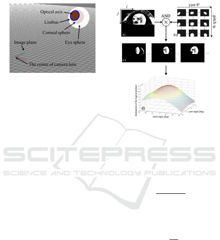
Figure 3: Generated 3D eye model consisting of the corneal
sphere and the eye sphere.
rent pose is estimated by the following evaluation
function:
ˆ
θ,
ˆ
ψ
= argmax
θ,ψ
m
∑
j=1
n
∑
i=1
B
ij
I
θψij
, (7)
where i and j are the image coordinates, and m and
n are the size of the image. The maximum value is
searched by using the hill-climbing algorithm, and we
obtain the current pose as
ˆ
θ and
ˆ
ψ. However, the es-
timated area of the iris is influenced by the area cov-
ered by the eyelid area as shown Figure 5(a). As the
objective of this research is to confirm the feasibil-
ity of a user calibration-free technique, we require a
good tracking result for consideration. Therefore, we
adjusted the estimated pose manually as shown in Fig-
ure 5(b).
4 GENERATING THE
UNWARPED CORNEAL
SURFACE IMAGE
The reflection image is distorted on the surface of
the cornea; hence, the unwarped image is generated
for estimating the point-of-regard. We assumed the
reflection on the cornea to be a specular reflection,
which is computed using the geometric relationship
between the eye model and the input image as shown
in Figure 6. The point P is the intersection of the
corneal sphere and the optical axis of the eye, and the
center of the tangent plane is located on P. When the
point on the tangent plane and the center of camera
lens are defined as T and S, respectively, the normal
vector N is computed by the following equation:
N = xS+ yT, (8)
where x and y satisfy the following equations under
Figure 4: Algorithm for iris tracking using the 3D eye
model. An inverted binary image(a) and the simulated im-
ages of the iris area (b) are used to compute the logical prod-
uct of these images(c). In addition, the area of the iris is
detected when the maximum value is found in the summed
values of the logical product(d).
the constraint of the specular reflection:
4cdy
4
− 4dy
3
+ (a+ 2b+ c − 4ac)y
2
+ 2(a− b)y+ a − 1= 0,
(9)
x =
(−2y
2
+ y+ 1)
(2by+ 1)
, (10)
where a = S· S, b = S· T, c = T· T, d = |S× T|
2
are
defined. When the biquadratic equation Equation 9 is
solved under the constraint x > 0 and y > 0, and the
vector N is computed. The reflection point R on the
surface of the corneal sphere is calculated by
R = r
C
N
kNk
. (11)
The unwarped image is created by the color infor-
mation obtained from the point R on the corneal sur-
face image. Actually, the color is extracted from the
input image using inverse ray tracking for estimating
the color of point R. For example, the unwarped im-
age is generated as shown in Figure 7, and the edge of
the basket is undistorted on the unwarped image.
User Calibration-free Method using Corneal Surface Image for Eye Tracking
69
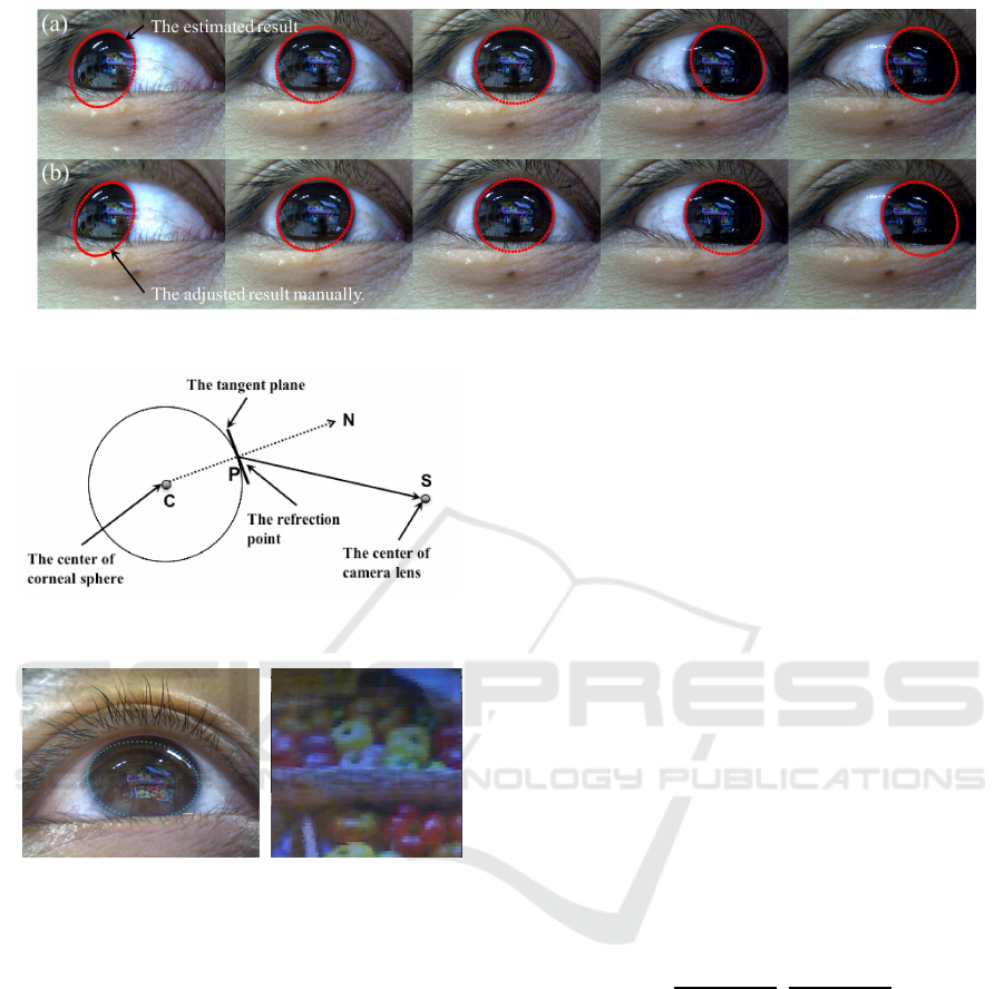
Figure 5: Area of the iris (a) estimated using model-based tracking, and (b) adjusted manually.
Figure 6: Relationship between the eyemodel and reflection
point.
(a) input image (b) unwarped image
Figure 7: Image of the cornea (a) input image, and (b) gen-
erated unwarped corneal surface image.
5 USER CALIBRATION-FREE
BASED ON CORNEAL
SURFACE IMAGE
In general, a user would have to look at several points
on a display for user calibration, because the visual
axis of the eye and the relationship between the eye
and the screen are determined to achieve high accu-
racy. In contrast, various methods have been pro-
posed as being user calibration-free, but there are var-
ious constraints. In the case of using a model-based
approach, the geometrical relationship between the
camera and the display is known in advance. In the
case of using regression-based approach, the user is
required to look at the display for a while, which is
why the point-of-regard cannot be estimated immedi-
ately. Therefore, we propose a user calibration-free
method without these constraints by using the corneal
surface image for providing high versatility.
5.1 Finding the Corresponding Area
between the Unwarped Corneal
Surface Image and the Display
Image
In our method, it is necessary to search the corre-
sponding area between the unwarped image and the
display image. When the corresponding point is de-
cided, the point is employed as the point-of-regard.
Additionally, it is possible to collect the points and the
eye pose for solving the regression formula. However,
the scales of the unwarped image and the display im-
age are different; thus, the scale is adjusted manually.
When we select two matched points E
1,2
and D
1,2
on
the unwarped image and the display image, respec-
tively, then the scale s is calculated by the following
equations:
[s
x
, s
y
] =
|D
1x
− D
2x
|
|E
1x
− E
2x
|
,
|D
1y
− D
2y
|
|E
1y
− E
2y
|
. (12)
The scale of the unwarped image is adjusted using s,
and the reflection point is searched on the display im-
age by template matching based on normalized cross
correlation. The image of the reflection area is huge
for detecting the corresponding area; thus, we ex-
tracted the image around the center of the unwarped
image as the template image. Figure 8(a) shows the
result of template matching when Figure 8(b) is em-
ployed as the template image.
The estimated corresponding area is the point-of-
regard; thus, we can estimate the point-of-regard im-
mediately. However, as the reflection on the cornea is
influenced by the illumination condition, it is difficult
to use the corresponding area continuously. There-
fore, the regression formula is obtained for improving
VISAPP 2017 - International Conference on Computer Vision Theory and Applications
70

Figure 8: Result image of template matching (a), and tem-
plate image(b). The area within the square is the result of
template matching.
the robustness. Details of the regression formula are
described below.
5.2 Regression Formula Obtained using
the Collected Point-of-regard
In the general regression approach, the Purkinje
points and the pupil centers are collected to solve the
regression expression when a user looks at several
points. In contrast, in our approach the regression for-
mula is solved while the point-of-regard is estimated
using the unwarped image. After that, the point-of-
regard is estimated by the regression expression using
the pose of the eye.
The area of the display was divided into nine ar-
eas, and the regression expression was calculated by
the nine points with a high cross-correlation value in
each area. The poses of the 3D eye model are de-
fined as (
ˆ
θ
1...9
,
ˆ
ψ
1...9
), and the point-of-regard on the
display image is also defined as (u
1...9
, v
1...9
). The re-
gression formula is calculated by the following equa-
tion:
u
1
, ··· , u
9
v
1
, ··· , v
9
= A
ˆ
θ
1
, ··· ,
ˆ
θ
9
ˆ
ψ
1
, ··· ,
ˆ
ψ
9
1, ··· , 1
. (13)
The matrix of the coordinate values of the display
image are defined as M, and the parameters of the re-
gression expression A is calculated using the pseudo-
inverse matrix M
+
by the following equation:
A =
ˆ
θ
1
, ··· ,
ˆ
θ
9
ˆ
ψ
1
, ··· ,
ˆ
ψ
9
1, ··· ,1
M
+
. (14)
Finally, the regression formula is obtained without
the user calibration procedure, and when the current
eye pose (
ˆ
θ
c
,
ˆ
ψ
c
) is determined, the point-of-regard
PoR can also be estimated using the regression ex-
pression by the following equation:
PoR = A
ˆ
θ
c
ˆ
ψ
c
1
. (15)
Figure 9: Environmental setup for the user calibration-free
method.
Figure 10: Image used for evaluating the accuracy of the
estimated point-of-regard in the evaluation experiment.
6 COMPARATIVE
EXPERIMENTS BETWEEN
THE CONVENTIONAL
CALIBRATION AND THE USER
CALIBRATION-FREE METHOD
6.1 Experimental Condition
We performed comparative experiments between the
conventional calibration and the user calibration-free
method to evaluate the accuracy of the estimated
point-of-regard. The four trial subjects wore the in-
strumental device consisting of the eye camera, and
the subjects looked in every hole and corner of the dis-
play on which a still image is shown. Figure 9 shows
the experimental condition, and the distance between
the display screen and the trial subjects is 800 mm.
In this experiment, it is not possible to use the chin
rest as an experimental installation, but we requested
subjects not to move their head.
6.2 Experimental Results
We solved the two regression formulas of the user
calibration-free and the conventional methods, re-
spectively. In the case of the conventional method,
the calibration points, which are used for solving the
regression expression, are collected manually. Af-
ter solving two regression expressions, trail subjects
User Calibration-free Method using Corneal Surface Image for Eye Tracking
71

Figure 11: Angular error of the estimated PoR by the con-
ventional method.
Figure 12: Angular error of the estimated PoR by the user
calibration-free method.
were requested to look at an image on which nine
crosses are drawn (Figure 10) for evaluating the es-
timated the point-of-regard. The angular errors of the
conventional method and the proposed method were
computed as shown in Figure 11 and Figure 12, re-
spectively.
6.3 Consideration
Currently, the accuracy of the conventional method
exceeds that of the proposed method; thus, we con-
sidered the cause of error through the results. In the
case of using the conventional calibration method, the
average of the angular error is 1.56 degrees, and the
angular error of each marker is closed. On the other
hand, the average of the angular error is 6.15 degrees
in the case of using the proposed method, and there is
great variability among each marker. We understood
that the cause of difference depended on the perfor-
mance of template matching, and it is necessary to
improvethe performanceof extracting the image from
the corneal surface.
7 CONCLUSIONS
In this paper, we proposed the user calibration-free
technique based on the use of a corneal surface im-
age. The corneal surface image was extracted using
a 3D model of the eye, and the point-of-regard for
solving the regression formula is estimated by tem-
plate matching. We succeeded in solving the relation-
ship between the display image and the eye pose us-
ing the regression expression, and we confirmed the
feasibility of the framework for the user calibration-
free based on the corneal surface image. The av-
erage of the angular error is around six degreesand
the modest performance was achieved without user-
calibration and hardware calibration. However, we
identified the need for some improvements through
the experiments. Currently, the accuracy is insuffi-
cient for using the point-of-regard in various applica-
tions; thus, the matching performance would have to
be improved in future. Additionally, the operator is
required to implement some manual settings; thus, it
is difficult to achieve auto-calibration in the current
implementation. These problems would need to be
addressed to automate the calibration.
ACKNOWLEDGMENT
This work was supported by Grant Number
16H02860.
REFERENCES
Khamis, M., Saltuk, O., Hang, A., Stolz, K., Bulling,
A., and Alt, F. (2016). Textpursuits: Using text for
pursuits-based interaction and calibration on public
displays. In Proc. of the 2016 ACM Int. Joint Conf. on
Pervasive and Ubiquitous Computing, UbiComp ’16,
pages 274–285.
Nagamatsu, T., Kamahara, J., and Tanaka, N. (2009).
Calibration-free gaze tracking using a binocular 3d
eye model. In CHI ’09 Extended Abstracts on Human
Factors in Computing Systems, pages 3613–3618.
Nishino, K. and Nayar, S. K. (2006). Corneal imaging sys-
tem: Environment from eyes. Int. J. Comput. Vision,
70(1):23–40.
Nitschke, C. and Nakazawa, A. (2012). Super-resolution
from corneal images. In Proc. of the British Machine
Vision Conference, pages 22.1–22.12.
Sugano, Y. and Bulling, A. (2015). Self-calibrating head-
mounted eye trackers using egocentric visual saliency.
In Proc. of the 28th Annual ACM Symp. on User In-
terface Software & Technology, UIST ’15, pages 363–
372.
VISAPP 2017 - International Conference on Computer Vision Theory and Applications
72

Takemura, K., Yamakawa, T., Takamatsu, J., and Oga-
sawara, T. (2014). Estimation of a focused object us-
ing a corneal surface image for eye-based interaction.
Journal of eye movement research, 7(3):4:1–9.
Wang, H., Lin, S., Liu, X., and Kang, S. B. (2005). Sep-
arating reflections in human iris images for illumina-
tion estimation. IEEE Int. Conf. on Computer Vision,
2:1691–1698.
User Calibration-free Method using Corneal Surface Image for Eye Tracking
73
