
Whispering Gallery Mode Emission of a Cylindrical Droplet Laser
Mitsunori Saito and Takuya Hashimoto
Department of Electronics and Informatics, Ryukoku University, Seta, Otsu 520-2194, Japan
Keywords: Droplet Laser, Stimulated Emission, Whispering Gallery Mode, Fluorescence, Silicone Rubber.
Abstract: A cylindrical droplet laser was fabricated in a silicone rubber by using a polyethylene-glycol solution of
rhodamine 6G. The silicone rubber provided a simple molding process for enclosing the droplet, since
silicone oil solidified at room temperature by only adding a curing agent. Polyethylene glycol dissolved a
large amount of dye molecules, yielding a fluorescent solution whose refractive index (1.46) was higher
than that of the silicone rubber (1.40). Consequently, some fluorescence rays circulated in the cylindrical
droplet owing to the total internal reflection on the side surface (the whispering gallery mode). Other
fluorescence rays made round trips in the radial or axial directions of the cylindrical droplet (the radial and
axial modes) being reflected at the side or bottom surfaces. When the droplet was excited by a green laser
pulse (wavelength: 527 nm, pulse duration: 10 ns), these emission modes competed with one another to
induce a stimulated emission. In a droplet with 2.0 mm diameter and 1.4 mm height, the whispering gallery
mode conquered the other emission modes, exhibiting a non-linear peak growth and a peak-width narrowing
when the excitation energy exceeded 20 μJ (the threshold energy of the stimulated emission).
1 INTRODUCTION
Whereas most optical devices are composed of
solids, liquids exhibit some excellent functions that
are unachievable with solids. Deformability
(fluidity) is an attractive property when creating
tunable or flexible devices. A simple fabrication
process is also an advantage of liquid devices; e.g.,
no polishing process is needed to create a droplet
with a smooth surface that acts as a microresonator
(Matsko, 2009). In a smooth droplet, which is
producible by spraying aerosol (Tzeng et al, 1984),
lightwave circulates with a low scattering loss and
generates a whispering gallery (WG) mode
(Campillo et al, 1991). In addition to fundamental
researches (Biswas et al, 1989), the WG mode
resonators have been studied extensively in various
technical fields including spectroscopy (Sasaki et al,
1997), biomedical sensing (Arnold et al, 2003), and
photonic signal control (Hara et al, 2005). Of
various applications, droplet lasers have been
studied most keenly in the last two decades (Barnes
et al, 1993). Droplets are usually suspended in air
(Kaqradag et al, 2013) or oil (Tanyeri et al, 2007),
and hence, handling difficulty and instability
become problems when creating a microlaser. These
problems are solved by enclosing a droplet in a
transparent silicone rubber (Saito et al, 2008).
Although droplets in the rubber can be handled like
a solid, their deformability (optical tunability) is
preserved owing to the flexibility of the rubber
(Saito and Koyama, 2012). Electrical tuning is also
achievable for a liquid-crystal droplet in a silicone
rubber (Humar et al, 2009).
In spherical resonators the WG modes are
excited in various planes because of the three-
dimensional symmetry. Fluorescent microspheres,
therefore, emit strong beams in various directions
even in the stimulated emission process. Although
the direction of the stimulated emission is
controllable by deforming the sphere (Schwefel et al,
2004), creation of a cylindrical or disklike droplet is
more preferable for restricting the WG mode plane.
A novel fabrication process has to be developed for
creation of cylindrical droplets. In addition,
fabricated droplets have to be enclosed in a solid
matrix, since the surface tension causes the cylinder
to deform into a sphere in free space (air or oil).
Silicone rubber seems useful for both creating and
enclosing a cylindrical droplet.
Figure 1(a) shows the WG mode in a cylindrical
droplet. Figs. 1(b) and 1(c) show two other modes in
which lightwave propagates in the radial or axial
direction. These modes compete with one another to
induce a stimulated emission; i.e., when a stimulated
emission
takes place in a certain mode, it suppresses
spontaneous emission of the other modes. (Saito and
Ishiguro, 2006). The WG mode emission is unique
32
Saito M. and Hashimoto T.
Whispering Gallery Mode Emission of a Cylindrical Droplet Laser.
DOI: 10.5220/0006089800320038
In Proceedings of the 5th International Conference on Photonics, Optics and Laser Technology (PHOTOPTICS 2017), pages 32-38
ISBN: 978-989-758-223-3
Copyright
c
2017 by SCITEPRESS – Science and Technology Publications, Lda. All rights reserved
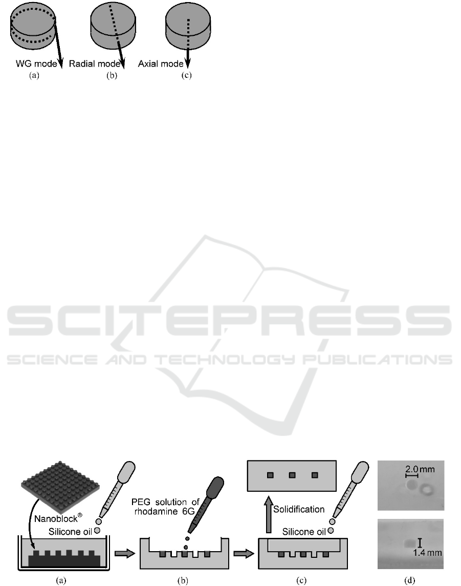
Figure 1: Schematic illustration of the emission modes in a
cylindrical droplet, i.e., (a) the whispering gallery, (b)
radial, and (c) axial modes.
to circulation-type resonators, whereas the other
emission modes are attainable with ordinary straight
waveguides. In addition, the WG mode exhibits
some attractive features for uses in sensors and
communications, e.g., a strong coupling with a
surrounding field or neighboring resonators. It is
preferred from this viewpoint to promote the
stimulated emission in the WG mode. The stimula-
ted emission occurs in a mode that has a higher gain
and/or a lower loss than the other modes. The
roughness of the cylinder surface causes a serious
optical loss to the WG mode in comparison with the
other modes, since circulating light suffers scattering
at every reflection occasion. A large gain, which is
related to the dye concentration and the droplet size,
promotes a stimulated emission in the radial or axial
mode, since lightwave is amplified strongly in a
round trip between the opposing surfaces. These
conditions have to be examined carefully to promote
the WG mode emission.
In this study, we fabricated cylindrical droplets
in a silicone rubber by using a molding technique.
Then
we measured fluorescence spectra by exciting
a cylindrical droplet from either the flat bottom or
the curved side. Spectral measurements were
conducted at various positions of the droplet to
evaluate the emission intensity of the three modes.
2 SAMPLE PREPARATION
Figure 2 shows the fabrication process of the
cylindrical droplets. A piece of building blocks, i.e.,
Nanoblock
®
(Kawada Co., Ltd., 2012), which had
bumps with 2.0 mm diameter and 1.4 mm height,
was used as a mold for creating cylindrical pits on a
silicone surface. As Fig. 2(a) shows, this plastic
plate was placed on the bottom of a plastic case (30
mm square), and then, the case was filled up with
silicone oil containing a curing agent (Shin-Etsu,
KE103). The curing agent promoted a bridging
reaction between silicone (polydimethylsiloxane)
molecules, and consequently, the oil solidified in 8 h.
As Fig. 2(b) shows, the silicone rubber that was
taken out of the case had a pit array corresponding to
the bumps of the plate.
A solvent for preparing a dye solution has to be
selected carefully. A solvent consisting of a large
molecule is preferred, since molecules of ordinary
solvents, e.g., methanol and toluene, disperse into
the silicone rubber through a large free volume in
the flexible matrix (Saito et al, 2015). A high index
of refraction is another requirement for the solvent,
since the total internal reflection at the droplet
surface is essential to generate the WG mode. The
solubility of dye molecules is of course an important
issue. Taking into account these requirements for the
solvent,
we selected polyethylene glycol (PEG)
with a molecular weight of 300. This solvent has a
refractive index of 1.46, which is higher than that of
the silicone rubber (1.40). Rhodamine 6G (Tokyo
Chemical Industry) was dissolved into PEG at a
concentration of 10
-3
mol/l. As Fig. 2(b) shows, this
dye solution was put into some selected pits on the
silicone rubber. The other pits were left empty to
avoid optical interaction between neighboring
droplets.
Figure 2: Fabrication process of cylindrical droplets. (a) A plastic plate with cylindrical bumps (Nanoblock®) is fixed on
the bottom of a plastic case, and silicone oil with a curing agent is poured until it fills the entire case. (b) After solidification
(8 h), the silicone rubber is taken out of the case. Then a dye solution is put into some selected pits that have been created
by the bumps. (c) The silicone oil with the curing agent is poured into the hollow of the rubber surface to enclose the dye
solution. (d) Top and side views of a droplet in the silicone rubber.
Whispering Gallery Mode Emission of a Cylindrical Droplet Laser
33
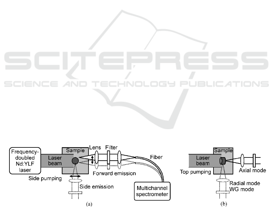
Finally, silicone oil with the curing agent was
poured on the concave of the silicone rubber, as
shown in Fig. 2(c). When solidification was comple-
te (8 h later), a silicone rubber containing cylindrical
droplets was obtained. The micrographs in Fig. 2(d)
show the top and side views of a cylindrical droplet
that is enclosed in the silicone rubber.
3 EXPERIMENT
Fluorescence spectra of the droplets were measured
by using an optical system shown in Fig. 3(a). The
pump light was a frequency-doubled Nd:YLF laser
of 527 nm wavelength. A single pulse of 10 ns
duration was shot at the occasion of a trigger signal
input. The pulse energy was adjusted between 15
and 170 μJ by using an attenuator. The laser beam
diameter was ~4 mm, and hence, the beam irradiated
the entire droplet with a nearly uniform intensity
distribution. Fluorescence was collected by a lens
system consisting of two convex lenses and a long-
pass filter that cut off the pump light. The collected
light was transmitted through an optical fiber (core
diameter: 400 μm) and detected by a multichannel
spectrometer.
Measurements were conducted in
either the forward or side direction, and the detection
point was changed by moving a micropositioner on
which the lens system and the fiber were mounted.
When the fluorescence was picked up at the cylinder
edge, the WG mode emission was detected. The
radial mode emission was measured by moving the
pickup point to the cylinder center. The radial mode
emission was measureable from the cylinder top or
bottom (flat surface). As Fig. 3(b) shows,
measurements were also conducted by irradiating
the pump light from the cylinder top.
4 RESULTS
First, fluorescence was measured by irradiating the
pump beam from the cylinder top, as shown in Fig.
3(b). Figures 4(a) and 4(b) show fluorescence
spectra that were measured at the edge or the center
of the curved surface, corresponding to the WG and
radial modes, respectively. Figure 4(c) shows a
spectrum of the axial-mode emission that emerged
from the cylinder bottom (the flat surface). The
radial- and axial-mode emissions exhibit a similar
broad spectrum, which usually appears in a
spontaneous emission process. In comparison with
these spectra, the fluorescence peak of the WG-
mode emission is higher and narrower. This fact
indicates that the stimulated emission takes place in
the WG mode. The stimulated emission, however,
seems to be in its early stage, since the peak
narrowing is still insufficient (FWHM: ~20 nm).
Next, the pump light was irradiated on the side
surface of the cylinder, as shown in Fig. 3(a).
Fluorescence
was measured in the forward direction.
Figures 5(a)‒5(e) show the fluorescence spectra that
were measured at several different positions by
moving the pickup lens system laterally. The
position that is designated as 0.0 mm corresponds to
the cylinder center (the radial mode), and ±1.0 mm
corresponds to the edge (the WG mode). The pump
light energy was varied between 15 and 170 μJ. As
Figs. 5(d) and 5(e) show, a fluorescence peak grew
nonlinearly as the pump energy increased. The peak
width (FWHM) decreased to ~4 nm at 170 μJ. These
facts indicated that a stimulated emission took place
in the WG mode. The ‘red-shift’ of the fluorescence
peak, which commonly takes place in the stimulated
emission process of dye lasers, is also visible in the
spectrum
(the peak shift to 590 nm at 170 μJ). By
contrast, a weak, broad fluorescence peak appeared
Figure 3: Optical setup for fluorescence measurements. A pump laser beam (4 mm diameter) irradiated a droplet (2 mm
diameter, 1.4 mm height) from (a) the side (curved surface) or (b) the top (flat surface). Fluorescence was picked up by
using a confocal lens system and a glass fiber (core diameter: 400 μm), and measured by a multichannel spectrometer. A
color filter was inserted to attenuate the residual pump laser beam. As the arrows show, this pickup system was moved
laterally to measure the fluorescence at the center or the edge of the droplet. Measurements were conducted in both forward
and side directions.
PHOTOPTICS 2017 - 5th International Conference on Photonics, Optics and Laser Technology
34
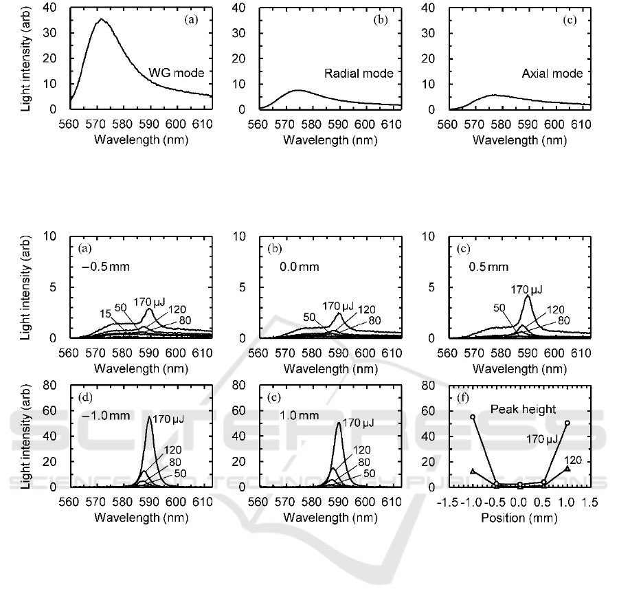
Figure 4: Fluorescence spectra that were measured by the top pumping configuration (Fig. 3(b)). (a) The WG- or (b) radial-
mode emission was measured from the droplet side by adjusting the pickup position to the edge or the center, respectively.
(c) The axial-mode emission was measured in the forward direction. The pulse energy and duration of the pump laser were
170 μJ and 10 ns, respectively.
Figure 5: (a‒e) Fluorescence spectra that were measured in the forward direction during the side pumping process (Fig.
3(a)). Measurements were conducted at (b) the droplet center (0.0 mm), (d, e) the edges (±1.0 mm), and (a, c) the halfway
points (±0.5 mm). The numerals beside the spectra denote the pump energies. (f) The position dependence of the peak
height.
in the other positions (0 and ±0.5 mm), as shown in
Figs. 5(a)‒5(c). The peak that emerged unnaturally
at 590 nm seemed to be caused by scattering of the
WG-mode emission, since both the spectral shape
and the pump-energy dependence of this peak
resembled those in Figs. 5(d) and 5(e). Figure 5(f)
shows the position dependence of the spectral peak
height. The fluorescence intensities at the central
portions (the radial mode) were negligible in
comparison with those at the edges (the WG mode).
The fluorescence in the axial direction was even
weaker (below the detection limit). As these facts
indicated, only a spontaneous emission took place in
the radial and axial modes.
As the dotted lines in Fig. 3(a) illustrate,
fluorescence measurements were conducted in the
side direction as well. Figures 6(a)‒6(e) show the
fluorescence spectra that were measured at various
positions on the cylinder side. As Fig. 6(e) shows, a
narrow peak is visible at the edge (1.0 mm) that is
distant from the position of the pump light
irradiation (‒1.0 mm). The peak height and width
are close to those measured in the forward direction
(Figs. 5(d) and 5(e)). This is a reasonable result,
since the WG mode usually yields the same
emission intensity in all directions along the curved
cylinder surface. As Fig. 6(d) shows, however,
strong peaks emerged at the irradiated edge. The
peak height is three-fold higher than those measured
at the other edges. As Figs. 6(a)‒6(c) show, the
fluorescence spectra at the central portions (0 and
±0.5 mm) are also different from those measured in
Whispering Gallery Mode Emission of a Cylindrical Droplet Laser
35
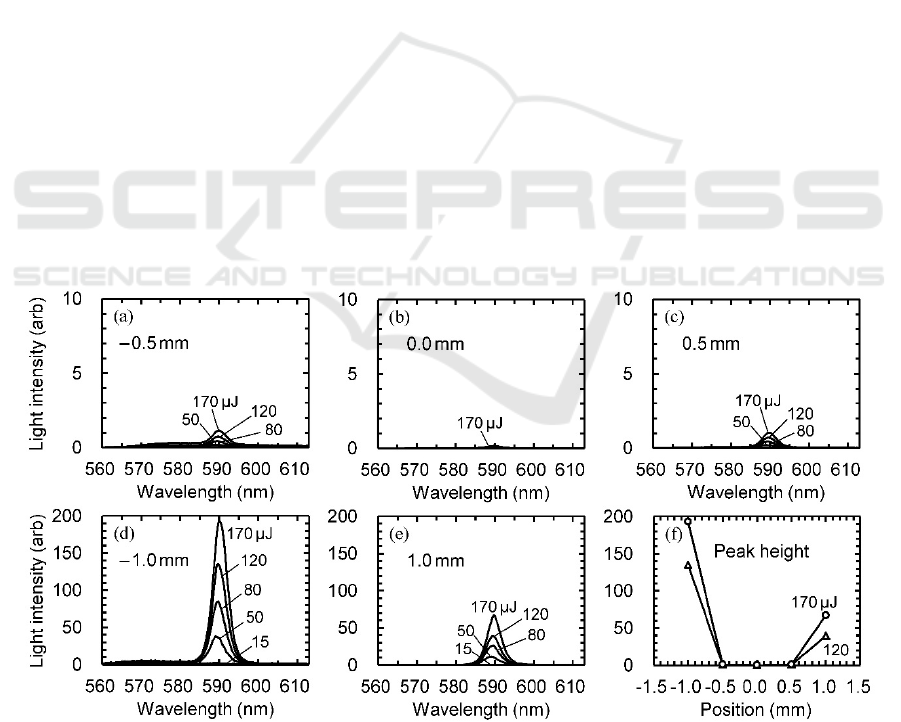
the forward direction (Figs. 5(a)‒5(c)). The peak at
590 nm is thought to be caused by the scattered WG-
mode light. If this peak is excluded, the radial-mode
emission is weaker in the side direction than the
forward direction. These phenomena are discussed
in the following section. Figure 6(f) shows the peak
heights that were measured at various positions. The
fluorescence emission is localized at the cylinder
edges, indicating occurrence of a strong WG-mode
emission.
5 DISCUSSION
Let us consider the mode competition on the basis of
the experimental results. The absorbance of the
pump light is higher than 90% in the current droplet.
This fact indicates that the dye molecules are excited
more strongly on the irradiation side than the
opposite side. When the pump light is irradiated
from the top (Fig. 3(b)), the excitation is
comparatively uniform or axially symmetrical in the
droplet, and accordingly, all modes are excited
evenly. As Fig. 4 shows, therefore, this excitation
method yields no absolute winner of the
competition; i.e., all modes emit spontaneous
emission although symptoms of stimulated emission
are visible in the WG mode. By contrast, when the
cylinder side is irradiated (Fig. 3(a)), the central
portion of the droplet receives a small pump energy,
whereas a semi-periphery on the irradiation side
absorbs a strong energy. This is the reason that the
axial-mode emission is negligible when the pump
light is irradiated from the side. It follows that the
side pumping is more preferable than the top
pumping for promotion of the WG-mode emission.
The radial emission at the droplet center (0.0
mm) is stronger in the forward direction (Fig. 5(b))
than the side direction
(Fig. 6(b)). This phenomenon
is also explained by the non-uniformity of excitation.
The radial-mode light that emerges in the forward
direction passes through the irradiation point where
strong excitation takes place. The radial-mode light
in the side direction, however, passes the region
apart from the excitation point. This difference in the
excitation strength causes the anisotropy in the
radial-mode emission.
As mentioned earlier, the WG mode usually
emits fluorescence uniformly along its optical path
(the periphery). If a portion of the optical path is
excited strongly, however, the circulating light is
amplified strongly at that portion. Since the outward
radiation is proportional to the circulating light
intensity, the WG-mode emission possibly becomes
strong at around the excitation point. This is the
reason that the strong fluorescence peak emerges at
the irradiation edge (Fig. 6(d)). This local radiation
enhancement seems useful to extract a light energy
efficiently at a specific point. If the circulating light
is confined strongly in the droplet, i.e., if the WG
Figure 6: (a‒e) Fluorescence spectra that were measured in the direction perpendicular to the pump beam axis, i.e., the
downward direction in Fig. 3(a). Measurements were conducted at different positions; i.e., (b) the droplet center (0.0 mm),
(d) the pumping side (‒1.0 mm), (e) the opposite side (1.0 mm), and (a, c) the halfway points (±0.5 mm). The numerals
beside the spectra denote the pump energies. (f) The position dependence of the fluorescence peak height.
PHOTOPTICS 2017 - 5th International Conference on Photonics, Optics and Laser Technology
36
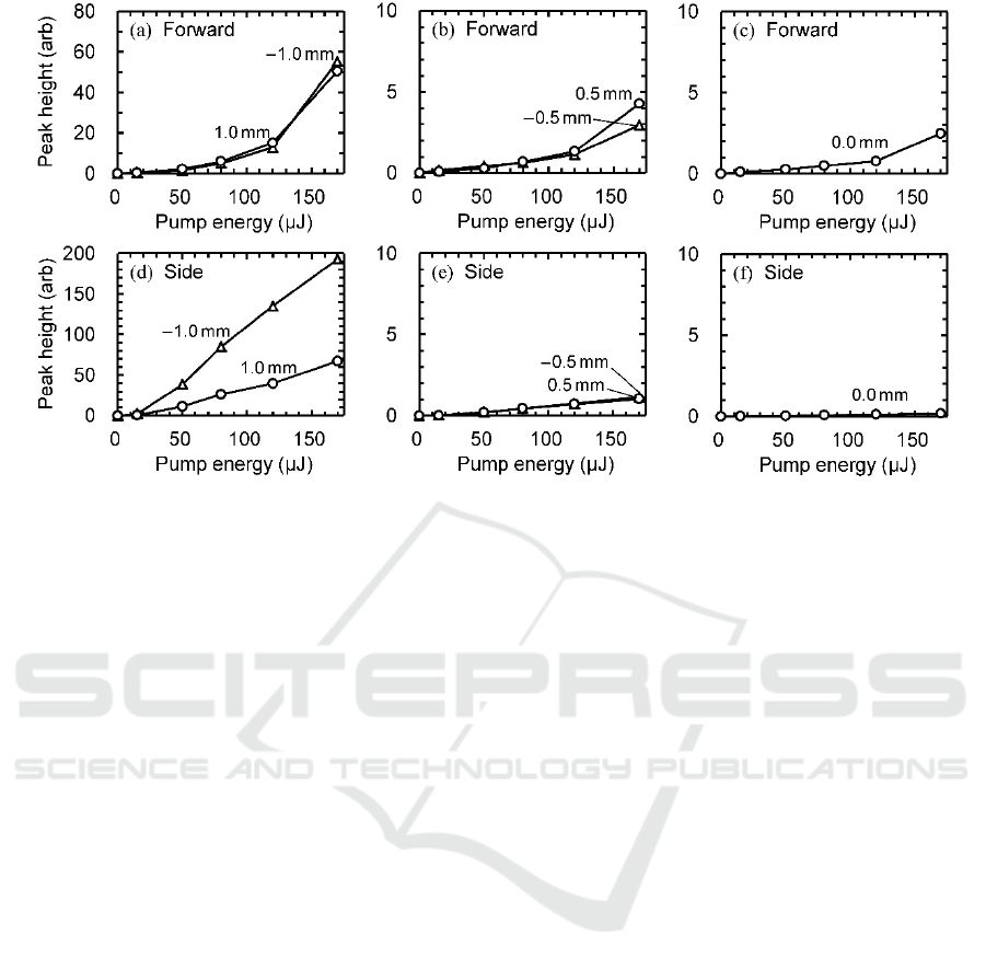
Figure 7: The pump-energy dependence of the fluorescence intensity (peak height). (a)‒(c) and (d)‒(f) correspond to the
data that were shown in Figs. 5 and 6, respectively. (a) and (d) show the data for the WG-mode emission. (c) and (f) show
the data for the radial-mode emission.
mode is weakly coupled to the outer electromagnetic
field, the outward radiation loss is small, and hence,
the circulating light propagates to the opposite side
with a small attenuation. If this is the case, the
intensity of the WG-mode emission becomes the
same at all positions; i.e., no local radiation
enhancement takes place. From this viewpoint, it is
preferable to enclose a droplet in a silicone rubber,
since
a small difference in their refractive indices
enhances a coupling efficiency between the WG
mode and the outer field.
Figures 7(a)‒7(c) show the pump-energy
dependences of the fluorescence peak height, which
were plotted on the basis of the experimental results
in Fig. 5 (the forward direction). As Fig. 7(a) shows,
the WG-mode emission exhibits a nonlinear peak
growth when the pump energy exceeds 50‒100 μJ.
Although similar nonlinear characteristics are visible
at the other positions (Figs. 7(b) and 7(c)), the
spectral peaks at these positions are attributed to the
scattering of the WG-mode light. Figure 7(d) shows
the peak heights of the WG mode that were
measured in the side direction (Figs. 6(d) and 6(e)).
At the irradiated edge (‒1.0 mm), the stimulated
emission takes place when the pump energy exceeds
~20 μJ. As regards the opposite edge (1.0 mm), the
threshold is not clear, i.e., the gradient of the curve
increases gradually as the pump energy increases.
This gradual increase is similar to those of the
curves in Fig. 7(a). The plots in Figs. 7(e) and 7(f)
also show a similar dependence (gradual increase)
on the pump energy. It is therefore assumed that
these emission peaks are caused by scattering of the
WG mode light.
In the current experiments, the silicone rubber
proved to be useful for both shaping a cylindrical
droplet and providing a suitable refractive index.
PEG is also a promising solvent, since it induces
random
lasing in the translucent solid phase (Saito
and Nishimura, 2016). With these useful materials,
we are currently planning new experiments, which
include spectral tuning by sample deformation, near-
field coupling of the cylindrical droplets, and
bistable laser emission owing to the phase transition
in PEG.
6 CONCLUSIONS
A fabrication process of a cylindrical droplet laser
was established by using a molding technique of a
silicone rubber. A stimulated emission in the WG
mode was realized by exciting the droplet (2.0 mm
diameter and 1.4 mm height) with a green laser
pulse (10 ns, 20 μJ). The excitation from the curved
surface was effective for both suppression of the
other emission mode and efficient extraction of the
WG mode emission. The combination of silicone
rubber and polyethylene glycol can be extended to
creation of various composite materials and devices
including a flexible microresonator and a droplet
laser array.
Whispering Gallery Mode Emission of a Cylindrical Droplet Laser
37

ACKNOWLEDGEMENTS
This research was supported by Japan Society for
the Promotion of Science (15K04642).
REFERENCES
Matsko, A. B., ed., 2009. Practical Applications of
Microresonators in Optics and Photonics, CRC Press.
Boca Raton, Florida.
Tzeng, H.-M., Wall, K. F., Long, M. B., Chang, R. K.,
1984. Laser emission from individual droplets at
wavelengths corresponding to morphology-dependent
resonances. Opt. Lett. 9(11). p. 499–501.
Campillo, A. J., Eversole, J. D., Lin, H.-B., 1991. Cavity
quantum electrodynamic enhancement of stimulated
emission in microdroplets. Phys. Rev. Lett. 67(4). p.
437–440.
Biswas, A., Latifi, H., Armstrong, R. L., Pinnick, R. G.,
1989. Time-resolved spectroscopy of laser emission
from dye-doped droplets. Opt. Lett. 14(4). p. 214–216.
Sasaki, K., Fujiwara, H., Masuhara, H., 1997. Optical
manipulation of a lasing microparticle and its
application to near-infrared microspectroscopy. J. Vac.
Sci. Technol. B, 15(6). p. 2786–2790.
Arnold, S., Khoshsima, M., Teraoka, I., Holler, S.,
Vollmer, F., 2003. Shift of whispering-gallery modes
in microspheres by protein adsorption. Opt. Lett. 28(4).
p. 272–274.
Hara, Y., Mukaiyama, T., Takeda, K., Kuwata-Gonokami,
M., 2005. Heavy photon states in photonic chains of
resonantly coupled cavities with supermonodispersive
microspheres. Phys. Rev. Lett. 94(20). p. 203905-1–4.
Barnes, M. D., Ng, K. C., Whitten, W. B., Ramsey, J. M.,
1993. Detection of single rhodamine 6G molecules in
levitated microdroplets. Anal. Chem. 65(17). p. 2360–
2365.
Kaqradag, Y., Aas, M., Jonáš, A., Anand, S., McGloin, D.,
Kiraz, A., 2013. Dye lasing in optically manipulated
liquid aerosols. Opt. Lett. 38(10). p. 1669–1671.
Tanyeri, M., Perron, R., Kennedy, I. M., 2007. Lasing
droplets in a microfabricated channel. Opt. Lett.
32(17). p. 2529–2531.
Saito, M., Shimatani, H., Naruhashi, H., 2008. Tunable
whispering gallery mode emission from a
microdroplet in elastomer. Opt. Express, 16(16). p.
11915–11919.
Saito, M., Koyama, K., 2012. Spatial and polarization
characteristics of a deformed droplet laser. J. Opt.
14(6). p. 065002-1–6.
Humar, H., Ravnik, M., Pajk, S., Muševič, I., 2009.
Electrically tunable liquid crystal optical
microresonators. Nature Photon. 3. p. 595–600.
Schwefel, H. G. L., Rex, N. B., Tureci, H. E., Chang, R.
K., Stone, A. D., Ben-Messaoud, T., Zyss, J., 2004.
Dramatic shape sensitivity of directional emission
patterns from similarly deformed cylindrical polymer
lasers. J. Opt. Soc. Am. B, 21(6). p. 923–934.
Kawada Co., Ltd. (Japan), 2012. What’s Nanoblock?
http://www.diablock.co.jp/kawada/en/nanoblock/about.
Saito, M., Ishiguro, H., 2006. Anisotropic fluorescence
emission of a dye-doped fibre ring that is pumped by a
ring laser beam. J. Opt. A: Pure Appl. Opt. 8(1). p.
208–213.
Saito, M., Nishimura, T., Hamazaki, T., 2015. Fade-
resistant photochromic reactions in a self-healable
polymer. Opt. Express, 23(20). p. 25523–25531.
Saito, M., Nishimura, Y., 2016. Bistable random laser that
uses a phase transition of polyethylene glycol. Appl.
Phys. Lett. 108(13). p. 131107-1–4.
PHOTOPTICS 2017 - 5th International Conference on Photonics, Optics and Laser Technology
38
