
Manufacturing and Optimization of Sol-gel-based TiO
2
-SiO
2
thin
Films as High Refractive Index Overlays for Long Period
Grating-based Biosensing
Palas Biswas
1
, Francesco Chiavaioli
2
, Sunirmal Jana
1
, Somnath Bandyopadhyay
1
,
Nandini Basumallick
1
, Ambra Giannetti
2
, Sara Tombelli
2
, Susanta Bera
1
, Aparajita Mallick
1
,
Francesco Baldini
2
and Cosimo Trono
2
1
Central Glass and Ceramic Research Institute, CSIR-CGCRI, 196 Raja S C Mullick Road, Kolkata 700032, India
2
Institute of Applied Physics “Nello Carrara”, CNR-IFAC, Via Madonna del Piano 10, 50019 Sesto Fiorentino, Italy
Keywords: Long Period Gratings, Sol-gel Overlay, High Refractive Index Thin Film, Refractometer, Biosensor.
Abstract: The manufacturing procedure and the optimization of high refractive index overlays for long period grating-
based sensors are reported. The overlay consists of a sol-gel-based TiO
2
-SiO
2
thin film. By carefully tuning
the overlay thickness and refractive index, it is possible to bring the LPG in the so-called transition mode
working region, and to optimize and maximize the LPG sensing performances. LPGs are here characterized
as optical refractometers, and, after a suitable functionalization of the sol-gel coated fiber surface, as
biosensors performing an IgG/anti-IgG bioassay.
1 INTRODUCTION
The optical label-free detection of chemical
compounds or biological species is based on the
modulation of the refractive index (RI) occurring at
the liquid/solid sensor interface, where the
biochemical interaction between the sensing layer
and the analyte of interest takes place (Fan, 2008).
Generally, the RI modification modulates the
evanescent wave component of the total optical
power. The literature accounts for several optical
configurations, mainly based on surface plasmon
resonance (SPR) (Homola, 2008), on localized SPR
(Willets and Van Duyne, 2007), on interferometry
(Queirós et al., 2011) or on optical resonance-based
structures (Kindt and Bailey, 2013). The substrate on
which the sensing layer is deposited is generally an
optical waveguide that allows both the interaction
light-analyte and the transport of the optical signal.
Recently, optical fiber long period gratings
(LPGs) have been proposed as a promising tool for
label-free biosensors (Chiavaioli et al., 2015; Baldini
et al., 2012). They exploit the typical peculiarities and
advantages of optical fiber sensors, such as
compactness, lightweight, intrinsic miniaturization,
high compatibility with optoelectronic devices,
remote measurement capabilities and multiplexing
thanks to the spectral modulation of the signal.
An LPG is produced by inducing periodic RI
perturbations in the core of a single-mode optical
fiber. When the light normally guided into the fiber
core interacts with the grating, the fundamental core
mode couples to co-propagating cladding modes at
well-defined resonance wavelengths (LPG
res
)
which satisfy the phase-matching condition
expressed by the characteristic equation of LPGs
(Erdogan, 1997):
res
(
m
)
= ( n
eff,core
– n
eff,clad
(
m
)
)
(1)
where is the grating period (usually in the range
from 100 m to 600 m), n
eff,core
and n
eff,clad(m)
represent the effective RIs of the fundamental core
mode (i.e. LP
01
) and the m-th cladding mode (i.e.
LP
0m
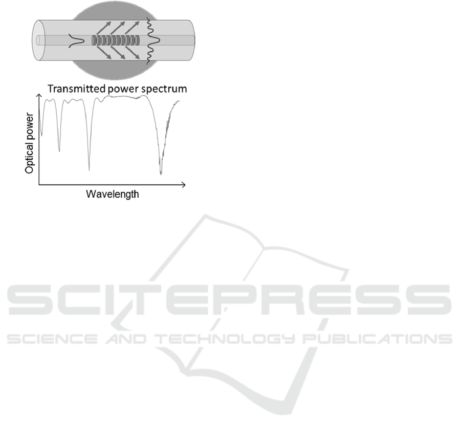
), respectively. Therefore, the transmission
spectrum of an LPG will be characterized by one or
more attenuation bands (Figure 1), in which the
minimum of each band corresponds to the coupling
with a selective m-th cladding mode. The cladding
refractive index n
eff,clad
will therefore depend on the
RI of the surrounding medium (n
sur
) and this feature
allows to use LPGs as RI sensors.
The optical mechanism of LPG-based biosensing
can be explained considering that the binding
interactions on the fiber surface produce a change of
Biswas, P., Chiavaioli, F., Jana, S., Bandyopadhyay, S., Basumallick, N., Giannetti, A., Tombelli, S., Bera, S., Mallick, A., Baldini, F. and Trono, C.
Manufacturing and Optimization of Sol-gel-based TiO2-SiO2 thin Films as High Refractive Index Overlays for Long Period Grating-based Biosensing.
DOI: 10.5220/0005844103490355
In Proceedings of the 4th International Conference on Photonics, Optics and Laser Technology (PHOTOPTICS 2016), pages 351-357
ISBN: 978-989-758-174-8
Copyright
c
2016 by SCITEPRESS – Science and Technology Publications, Lda. All rights reserved
351
the n
eff,clad
and, consequently, a shift of the LPG
res
.
Figure 1: LPG working principle (top) and a typical LPG
transmission spectrum (bottom).
The best RI sensitivity of a standard LPG is
reached when n
sur
is close to the RI of fiber cladding
(i.e. 1.44–1.46 RIU, RI units), thus quite far from the
RI of water or aqueous solutions (i.e. 1.33–1.34 RIU)
(Patrick et al., 1998), in which practically all the
biochemical reactions occur. To overcome this
problem, the literature accounts for a general
approach that consists in the deposition over the fiber
of a nm-thick film overlay of RI higher than the
cladding RI (Del Villar et al., 2005). In this way the
RI range in correspondence of the maximum
sensitivity can be adjusted around 1.33 RIU. In this
case, values of RI sensitivity of the order of thousands
of nm RIU
-1
can be experimentally achieved (Pilla et
al., 2012).
Sol-gel-derived coatings have been used for years
to enhance the performance of evanescent wave
sensors. The sensor manufacturing is quite simple
thanks to the dip-coating (DC) technique (MacCraith,
1993), and the possibility of doping sol-gel coatings
with high refractive index materials provides the
chance for implementing high RI (HRI) film overlays
(Smietana et al., 2015; Davies et al., 2009).
In the present paper, the manufacturing procedure
and the optimization of a sol-gel-based TiO
2
-SiO
2
thin film as HRI overlay for LPG-based biosensing
applications were investigated. The HRI overlay,
deposited by means of the DC technique along the
sensing portion containing the LPG, improved the
sensor performance in terms of volume RI sensitivity
(as optical refractometer), and of bio-layer formation
sensitivity (as biosensor). An IgG/anti-IgG assay
implemented on the fiber sol-gel coated sensing
region was used to characterize the proposed LPG-
based device as a feasible and effective biosensor.
2 MATERIALS AND METHODS
2.1 LPG Fabrication
LPGs were manufactured in a standard single-mode
fiber (SMF28e of Corning Inc.) using point-to-point
technique (Hill and Meltz, 1997) by means of a KrF
pulsed Excimer laser (Braggstar-500, TUI laser,
Germany, = 248 nm, repetition rate = 200 Hz, pulse
energy = 10 mJ) with = 342 m. The fiber was
previously hydrogen loaded at a pressure of 10.3 MPa
and a temperature of 100 °C for 48 hours to enhance
the photosensitivity. After the inscription, the fiber
was annealed at 150–170 °C for about six hours for
the stabilization of the optical characteristics of
LPGs. In order to deposit a glassy coating (e.g. a sol-
gel based thin film) over an optical fiber containing
an LPG, the grating region must be heated at around
450 °C during sintering the gel film. In general, at that
temperature, the LPG attenuation bands almost
reduce to zero. To overcome this problem, during the
grating manufacturing, the cladding mode of interest
(LP
07
) was intentionally overcoupled with a greater
coupling strength to achieve stable LPGs when heated
(Biswas, 2014). The LPGs were stabilized at 550 °C
and then gratings with a
res
of roughly 1590 nm, with
a visibility of the attenuation band of roughly -12 dB,
and with a full width at half maximum (FWHM)
bandwidth of roughly 20 nm were attained.
2.2 Sol-gel Preparation and Deposition
The preparation of the sol-gel was performed
according to previous literature (Chiavaioli et al.,
2015). Briefly, for the silica sol preparation, tetraethyl
orthosilicate (TEOS, reagent grade, 98%) was used at
a molar ratio water:TEOS:HCl of 2:1:0.001; for the
titania sol, tetraisopropylorthotitanate (TIOT, 97%)
was used at a molar ratio acetyl acetone:TIOT of 1:2.
The two sols were mixed by stirring for about 4 hours
and then kept to age for additional 24 hours. The Ti:Si
ratio and the total equivalent oxide weight percentage
(wt.%) were 1:1 and 7.3, respectively. To obtain a
thicker film, the viscosity of the sol was increased
from 3.2 mPa·s up to 27 mPa·s by controlling the
evaporation of the solvents through the warming of
the sol. Afterwards, the LPG was heated in a furnace
in order to allow the oxide formation in the deposited
OSENS 2016 - Special Session on Optical Sensors
352

film. At the end of the process, the attenuation band
related to the LP
07
cladding mode was recorded both
in air and in phosphate buffered saline (PBS) solution.
Considering the Ti:Si volumetric ratio (1:1), a
layer RI of ~1.7 RIU can be estimated as the mean
value between the titania RI (i.e. 1.91–1.96 RIU) and
silica RI (i.e. 1.42–1.44 RIU) (Davies et al., 2015). To
optimize the sensor performance and to reach the
optimum overlay thickness (OOT), the film thickness
was varied by changing both the sol viscosity during
the sol preparation and the withdrawal speed during
the film deposition. A single deposition step was
found to be good enough to move the selected
cladding mode to its transition region (Cusano et al.,
2006).
During the heat treatment, the temperature of the
furnace was increased from 26 °C to 450 °C at a rate
of about 1.2 °C min
-1
and then the LPG was kept at
450 °C for about 2.5 hours. Later, the furnace
temperature was slowly cooled down with the same
rate of 1.2 °C min
-1
in order to avoid any crack due to
thermal shock. At the end of the process, the LPG
wavelength of LP
07
mode was measured in air and in
phosphate buffered saline (PBS) solution.
2.3 Experimental Setup
The experimental setup is detailed in Figure 2. The
flow-cell consists of two parts (Trono et al., 2011):
the upper one is a 4 mm thick PMMA transparent
layer, and the bottom one is a 6 mm thick aluminium
layer placed in thermal contact with a thermo electric
cooler (TEC) element. The flow cell is 80 mm long,
15 mm wide, and 10 mm high, and the flow-channel
total volume is roughly 50 L. The temperature
stabilization section of the flow cell makes use of a
thermistor, inserted into the aluminium bottom part as
close as possible to the flow channel, which acts as a
feedback element on the Peltier elements that are
driven by a suitable controller (ILX Lightwave LDC-
3722B TEC controller). The optical fiber containing
the LPG is glued at both the edges of the flow cell and
a thermocouple (Lutron TM-917) records the
temperature of the sensing environment during the
measurements. Each sample contained into the flask
is pumped inside the flow cell by means of a
peristaltic pump (Gilson Minipuls 3). The light is
launched by a broadband superluminescent diode
(SLD) INPHENIX IPSDD1503. The transmitted
spectrum is acquired by an optical spectrum analyzer
(OSA) Anritsu MS9030A – MS9701B (0.1 nm
spectral resolution).
Figure 2: schematic view of the experimental setup.
Longitudinal cross section (a) and top view (b) of the flow-
cell.
2.4 Data Processing
The optical bandwidth of the OSA is set at 20 nm with
the central wavelength roughly corresponding to the
expected LPG
res
. After recording the spectrum, the
procedure firstly evaluates the starting LPG
res
that
is the wavelength corresponding to the minimum of
the data set; then the fitting using the Lorentzian
function is carried out (normally a correlation greater
than 0.996 can be obtained) and provides the final
LPG
res
with an error of 7 pm – 8 pm. The whole
procedure is performed every 20 s, which is the
sensing system acquisition time. For each
experimental point, the minimum wavelength is
acquired at least 15 times. Therefore, each
experimental point is characterized by its own mean
value and the respective standard deviation. In this
way, the experimental standard deviation takes into
account the noise sources coming from not only the
extraction procedure of the LPG
res
but also all the
other noise sources related to the experimental setup
(e.g. temperature fluctuations). In addition, each
experimental point is recorded when the flow is
stopped, thus the temperature fluctuations can be
maintained lower than 0.05 °C during the measuring
time.
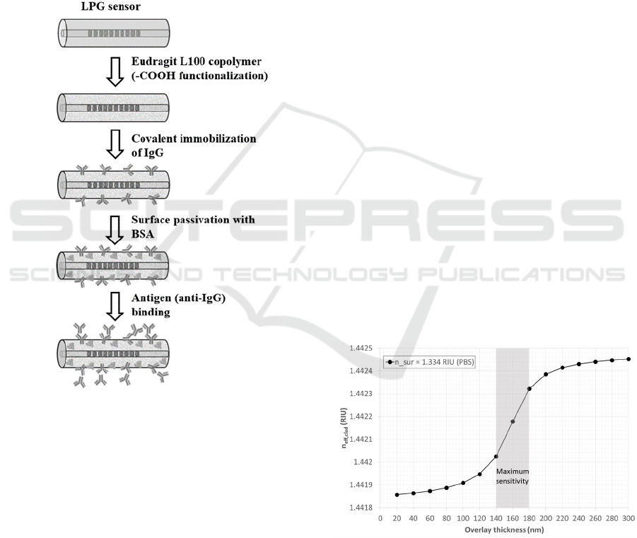
2.5 Bioassay Protocol
The step-by-step protocol followed to implement the
bioassay (Chiavaioli et al., 2014) is depicted in Figure
3. The functionalization of the optical fiber in
correspondence of the LPG was achieved by the
deposition of a layer of a methacrylic
acid/methacrylate copolymer (Eudragit L100) for
antibody immobilization.
Once the LPG was functionalized, the optical
fiber was placed inside the temperature-stabilized
flow cell. All the steps for the implementation of the
bioassay were performed using the flow cell
Manufacturing and Optimization of Sol-gel-based TiO2-SiO2 thin Films as High Refractive Index Overlays for Long Period Grating-based
Biosensing
353
connected to a peristaltic pump and keeping the
temperature of the flow cell at 23 °C. The preparation
of the biolayer consisted of the following steps
(Figure 3): activation of –COOH (carboxylic) groups
by cross-linking chemistry (1-Ethyl-3-[3-
dimethylaminopropyl] carbodiimide hydrochloride
(EDC) and N-hydroxysuccinimide (NHS)), covalent
immobilization of mouse IgG (1000 mg L
-1
in PBS),
washing with PBS for removing the un-reacted
antibodies, and surface passivation with bovine serum
albumin (BSA) (3% in PBS) in order to block the
remaining activated carboxylic groups and to prevent
non-specific adsorption onto the surface.
Figure 3: schematic representation of the biolayer
preparation on the fiber surface and of the antibody-antigen
binding phase.
The assay was performed in human serum spiked
with increasing concentrations of goat anti-mouse
IgG ranging from 1 µg L
-1
up to 100 mg L
-1
. Serum
was used at a final dilution of 1:10 (v/v) in PBS.
3 RESULTS
3.1 Thickness Optimization
The LPG RI sensitivity can be significantly enhanced
when covered with an overlay of a material having RI
higher than the one of the fibre. In these conditions,
the selected cladding mode starts to be guided by the
overlay and the LPG is working in the so-called
transition mode region (Del Villar et al., 2005). The
overlay thickness and RI must be precisely controlled
in order to reach the optimum overlay thickness
(OOT), which occurs when the cladding mode
resonance wavelength is positioned at the centre
between the original value and that one of the next
lower cladding mode (LP
06
in this case). The
behaviour of the LP
07
cladding mode as a function of
the thickness of the sol–gel overlay was calculated
considering sol-gel RI of 1.698 RIU and PBS buffer
(1.334 RIU) as surrounding medium. The simulated
curve, reported in Figure 4, demonstrates that the
sensors can work around the most sensitive linear
region when the overlay thickness is comprised
between 140 and 180 nm. In this way, the LP
07
mode
will be in the transition region when the surrounding
medium is PBS buffer, and the sensor will show a
higher sensitivity as a function of the biochemical
interaction of the target biomolecule with the sensing
layer.
Based on these simulations, the thickness of the
sol–gel-based TiO
2
-SiO
2
film overlay was optimized
by varying the viscosity of the sol and the withdrawal
speed during the film deposition. Three different
batches were realized, changing the sol viscosity
(batch A: 3.2 mPa·s; batch B: 27 mPa·s; batch C: 24.5
mPa·s) and the withdrawal speed (batch A: 2.5 mm
sec
-1
; batch B: 2.2 mm sec
-1
; batch C: 2.95 mm sec
-1
).
The corresponding wavelength shift for the LP
07
mode due to the film deposition was 8, 13.5 and 20
nm for batch A, batch B and batch C, respectively.
Figure 4: simulated curve, n
eff,clad
vs. overlay thickness
(1.698 RIU) considering the LP
07
mode PBS buffer as
surrounding medium.
The overlay RI can also slightly vary from the
desired value depending on:
-the sol composition;
OSENS 2016 - Special Session on Optical Sensors
354
-the ageing time of the sol that can directly
influence the viscosity of the sol:
-the withdrawal speed during dip coating;
-the thermal curing temperature.
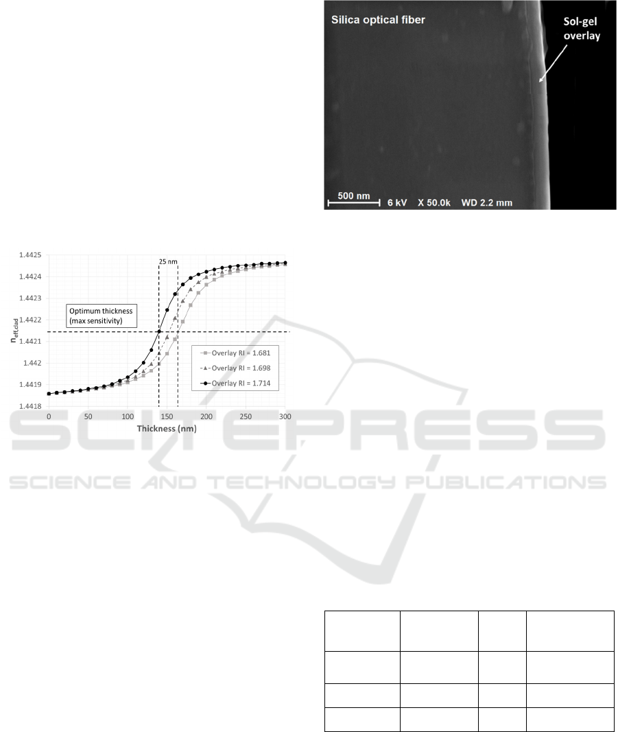
In order to evaluate the sensor response
dependence on this parameter, the effective RI of the
LP
07
mode was simulated as a function of the overlay
thickness, considering a ±1% change in the overlay
RI (1.681, 1.698 and 1.714 RIU) and considering PBS
as surrounding medium. The results are shown in
Figure 5. The ±1% variation of overlay RI slightly
changes the sensitivity without shifting the sensor
from the most sensitive region. Considering a ±1%
variation of the overlay RI, a tolerance on the overlay
thickness of about 25–35 nm is expected.
Figure 5: Simulated curves (overlay thickness vs n
eff,clad
)
used for studying the influence of a change of 1% in the
overlay RI (1.698 RIU, triangles grey dotted line; 1.681
RIU, squares, grey line; 1.714 RIU, circles, black line)
considering the LP
07
mode when the surrounding medium
is the PBS buffer.
The film overlay was analysed by means of a field
emission scanning electron microscope (FESEM;
Supra 35VP, Carl Zeiss). Figure 6 shows an image of
the cross-section of an optical fiber coated with the
sol-gel based TiO
2
-SiO
2
film overlay (sensor of batch
C). The thickness of the deposited sol-gel film
overlay was estimated to be (159 ± 10) nm
(Chiavaioli et al., 2015).
3.2 Bulk Refractive Index Sensitivity
For the RI characterization, the LPGs were immersed
in NaCl-in-water solutions of known RI: from 0.1%
wt., 1.333 RIU up to 0.6% wt., 1.334 RIU with step
of 0.1% wt. Each measurement was taken at stable
temperature of 23 °C with fluctuations lower than
0.03 ºC. This allows to discard the contribution
coming from the thermo-optic effect acting on
solutions (roughly -8 x 10
-5
RIU °C
-1
). After each
Figure 6: FESEM image of the cross-section of the optical
fiber coated with sol-gel based TiO
2
-SiO
2
film overlay
(batch C).
measurement, the fiber was washed with deionized
water in order to remove any remaining NaCl on the
overlay surface.
A comparison considering the same cladding
mode was carried out for three different LPGs (not
coated, batch A and B) in the RI range between 1.333
RIU and 1.334 RIU.
The results are summarized in table 1, while the
sensor response curve for a coated LPG of batch B is
reported in Figure 7. It is worth pointing out that the
sensitivity was evaluated considering the slope of the
linear regression approach of the sensor response
curve (Figure 7 as an example), whereas the
resolution was attained considering three times the
standard deviation divided by the sensitivity (Trono
et al., 2011).
Table 1: Comparison of the results achieved using different
sol-gel based titania-silica coated LPGs and conventional
not-coated LPG (same LP
07
mode order) in terms of volume
RI characterization.
Batch
Sensitivity
(nm RIU
-1
)
(pm)
Resolution
(RIU)
not coated
LPG
-29.8 8 8.1 x 10
-4
A -2044.5 10 1.5 x 10
-5
B -7075.3 11 4.6 x 10
-6
As shown in Table 1, there is a great improvement
(both sensitivity and resolution), going from a simple
not coated LPG to a coated LPG. Moreover, by
optimizing the thickness of the film overlay with
values around 130–175 nm considering PBS as
surrounding medium (RI of 1.334 RIU), it is possible
to achieve very good performances.
Manufacturing and Optimization of Sol-gel-based TiO2-SiO2 thin Films as High Refractive Index Overlays for Long Period Grating-based
Biosensing
355
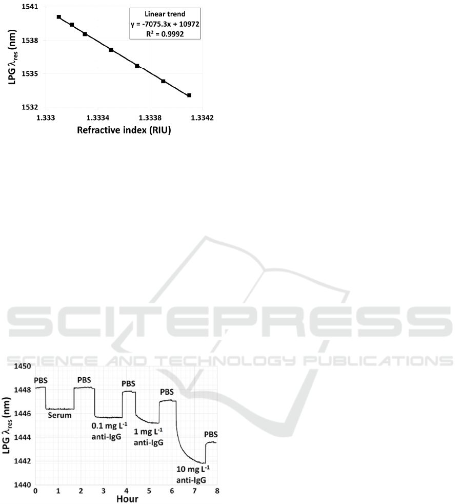
Figure 7: LPG wavelength shift (batch B) as a function of
the external volume refractive index.
3.3 Bioassay
The performances of sol-gel coated LPGs were
evaluated also by carrying out an IgG/anti-IgG
immunoassay on the functionalized surface of the
fiber. The sol-gel based TiO
2
-SiO
2
coated LPG of
batch C was used in this measurement. The
sensorgram achieved by spiking the antigen (from 0.1
mg L
-1
up to 10 mg L
-1
) in human serum is reported
in Figure 8. The duration of the whole immunoassay,
including the antibody immobilization step, was of
several hours, but the long-term stability of the
sensing system (Trono et al., 2011), guarantees the
absence of any disturbance coming from long-term
drifts.
Figure 8: Response of a sol-gel based TiO
2
-SiO
2
coated
LPG of batch C in human serum. Sample spiked with the
antigen (anti-IgG) at 0.1 mg L
-1
, 1 mg L
-1
and 10 mg L
-1
.
A limit of detection (LOD), defined as three times
the standard deviation of the blank measurement, of 8
g L
-1
was attained (Chiavaioli et al., 2015). The
LOD is nine-fold lower than that achieved in the same
experimental conditions (i.e. human serum) but using
a not coated LPG (Chiavaioli et al., 2014).
4 CONCLUSIONS
The manufacturing procedure and the optimization of
high refractive index sol-gel-based TiO
2
-SiO
2
thin
film overlay for LPG-based sensors have been
discussed. The sol-gel characteristics (composition
and viscosity) and the withdrawal speed during the
dip-coating technique have been chosen in order to
have the best combination of RI and thickness.
Sensors with overlay thickness of 130–160 nm and RI
of 1.7 RIU were manufactured and characterized. The
LPG sensors performances were evaluated, as optical
refractometer, with the volume refractive index
characterization, and as biosensor, with the IgG/anti-
IgG bioassay. The best performance was achieved
with an overlay thickness of roughly 159 nm, with a
bulk refractive index sensitivity of roughly 7000 nm
RIU
-1
, a resolution of the order of 10
-6
RIU in water
environment (refractometer), and a LOD of 8 g L
-1
(5.3 x 10
-11
M) in serum matrix (biosensor).
ACKNOWLEDGEMENTS
This research study was supported by the Joint
Research Proposal (No.22/EU/Italy/CNR/proj./2012)
under CNR, Italy−CSIR, India Bilateral S&T
Programme, entitled “Development of Long Period
Grating (LPG) based immunoassay for bio-sensing
applications”. F. Chiavaioli wishes to thank the
Italian Minister of University and Research (MIUR)
under the grant N. RBFR122KL1. S.Tombelli wishes
to thank the European Community for the project
Hemospec (FP7-611682).
REFERENCES
Baldini, F., Brenci, M., Chiavaioli, F., Giannetti, A., Trono,
C., 2012. Anal. Bioanal. Chem., 402, 109–116.
Biswas, P., Basumallick, N., Dasgupta, K.,
Bandyopadhyay, S., 2014. J. Lightwave Technol., 32,
2072−2078.
Chiavaioli, F., Biswas, P., Trono, C., Bandyopadhyay, S.,
Giannetti, A., Tombelli, S., Basumallick, N., Dasgupta,
K., Baldini, F., 2014. Biosens. Bioelectron., 60, 305–
310.
Chiavaioli, F., Biswas, P., Trono, C., Jana, S.,
Bandyopadhyay, S., Basumallick, N., Giannetti, A.,
Tombelli, S., Bera, S., Mallick, A., and Baldini F. 2015,
Anal Chem, DOI: 10.1021/acs.analchem.5b01841.
Cusano, A.; Iadicicco, A.; Pilla, P.; Contessa, L.;
Campopiano, S.; Cutolo, A.; Giordano, M., 2006. Opt.
Express, 14, 19–34.
OSENS 2016 - Special Session on Optical Sensors
356

Davies, E.; Viitala, R.; Salomäki, M.; Areva, S.; Zhang, L.;
Bennion, I. J., 2009. Opt. A: Pure Appl. Opt., 11,
015501.
Del Villar, I., Matías, I. R., Arregui, F. J., Lalanne, P., 2005.
Opt. Express, 13, 56–69.
Erdogan, T. J., 1997. Opt. Soc. Am. A, 14, 1760–1773.
Fan, X., White, I. M., Shopova, S. I., Zhu, H., Suter, J. D.,
Sun, Y., 2008. Anal. Chim. Acta, 620, 8–26.
Hill, K. O., Meltz, G. J., 1997. J. Lightwave Technol., 15,
1263–1276.
Homola, J., 2008. Chem. Rev., 108, 462–493.
Kindt, J. T., Bailey, R. C., 2013. Curr. Opin. Chem. Biol.,
17, 818–826.
MacCraith, B. D., 1993. Sens. Actuators B, 11, 29–34.
Patrick, H. J., Kersey, A. D., Bucholtz, F., 1998. J.
Lightwave Technol., 16, 1606–1612.
Pilla, P., Trono, C., Baldini, F., Chiavaioli, F., Giordano,
M., Cusano, A., 2012. Opt. Lett. 2012, 37, 4152–4154.
Queirós, R. B., Silvia, S. O., Noronha, J. P., Frazão, O.,
Jorge, P., Aguilar, G., Marques, P. V. S., Sales, M. G.
F., 2011. Biosens. Bioelectron., 26, 3932–3937.
Smietana, M., Koba, M., Brzozowska, E., Krogulski, K.,
Nakonieczny, J., Wachnicki, L., Mikulic, P.,
Godlewski, M., Bock, W. J., 2015. Opt. Express, 23,
8441–8453.
Trono, C., Baldini, F., Brenci, M., Chiavaioli, F., Mugnaini,
M., 2011. Meas. Sci. Technol., 22, 075204.
Willets, K. A., Van Duyne, R. P., 2007. Annu. Rev. Phys.
Chem., 58, 267–297.
Manufacturing and Optimization of Sol-gel-based TiO2-SiO2 thin Films as High Refractive Index Overlays for Long Period Grating-based
Biosensing
357
