
Mixed Hardware and Software Embedded Signal Processing Methods for
in-situ Analysis of Cardiac Activity
Bertrand Massot
1
, Tanguy Risset
2
, Gregory Michelet
1
and Eric McAdams
1
1
Lyon Institute of Nanotechnology, CNRS - INSA Lyon, University of Lyon, Villeurbanne, France
2
Centre of Innovation in Telecommunications and Integration of Service, INRIA - INSA Lyon, Villeurbanne, France
Keywords:
Wearable Sensors, Heart Rate, Heart Rate Variability, Biomedical Signal Processing, Body Sensors Network.
Abstract:
This paper presents the implementation of a combination of hardware and software signal processing methods
on a wearable device for the continuous and long-term monitoring and analysis of cardiac activity during in-
situ experiments. Heart rate assessment and heart rate variability parameters are computed in real-time directly
on the sensor, thus only few parameters are sent via wireless communication for power saving. Hardware
method for heart rate measurement, and software methods for the calculation of time-domain and frequency-
domain parameters of heart rate variability are described, and preliminary tests for the evaluation of the sensor
are presented.
1 INTRODUCTION
The continuous and long-term monitoring of an indi-
vidual’s vital signs enables a real-time and more rel-
evant health diagnosis, in order to set up appropriate
preventive measures, and to undertake rapid remedial
action in the case of early detection of symptoms; as,
for example, the latent anticipation of sudden cardiac
arrest (424 000 annual out-of-hospital cardiac arrests,
with an overall survival rate of only 5.2 % (Go et al.,
2014)) by evaluating the risks of cardiovascular dis-
ease and by detecting any cardiac abnormalities. This
in turn will result in more effective healthcare deliv-
ery, both financially and therapeutically (Van Hoof
and Penders, 2013) by avoiding untimely hospitaliza-
tion while ensuring patient safety and autonomy.
A promising solution is the development of wear-
able systems which assess relevant indicators en-
abling a direct, on-body cardiac diagnosis. Several
research projects’ results in this area have highlighted
a range of various technical challenges that must be
overcome (McAdams et al., 2011), (Massot et al.,
2013). The achievement of a suitable device for con-
tinuous, long-term monitoring of heart rate activity
will enable the detection of cardiac abnormalities in
the electrocardiogram signal (ECG), for example to
prevent ventricular fibrillation (VF), and to monitor
the instantaneous heart rate (HR), from which can be
derived several parameters regarding heart rate vari-
ability (HRV). HRV provides information on auto-
nomic nervous system (ANS) activity, a relevant indi-
cator for several pathologies (Malik et al., 1996) and
more generally on an individual’s stress and arousal.
New wearable devices for the monitoring of heart
rate activity can exploit the benefits of recent techno-
logical advances in electronics and wireless commu-
nication systems in order to overcome the challenges
previously cited. Prototypes developed in laborato-
ries already show really promising results in terms of
wearability, robustness and autonomy, as for exam-
ple the wearable patch developed at the Holst Centre
which benefits from both elaborated hardware (Altini
et al., 2011) and software (Romero et al., 2009), and
more recently from a new kind of dry electrode for
comfortable measurements (Chen et al., 2013). There
are already commercially available products for per-
sonal monitoring of one’s own cardiac rhythm, but
they are mainly aimed at well-being and fitness ap-
plications rather than being suitable for medical pre-
vention and diagnosis. Most of these systems suf-
fers from a lack of accuracy, depending on the sens-
ing method used : for example, plethysmography ap-
pears to be still questionable for instantaneous HR
and short-term HRV assessment and is highly sen-
sitive to motion artefacts in ambulatory conditions
(Sch
¨
afer and Vagedes, 2013). Also, filtering and in-
terpolating HR due to motion artefacts induces distor-
tion in frequency content of subsequent HRV param-
eters.
In this paper, we presents an optimized combi-
nation of robust and accurate methods for on-board
Massot, B., Risset, T., Michelet, G. and McAdams, E.
Mixed Hardware and Software Embedded Signal Processing Methods for in-situ Analysis of Cardiac Activity.
DOI: 10.5220/0005843703030310
In Proceedings of the 9th International Joint Conference on Biomedical Engineering Systems and Technologies (BIOSTEC 2016) - Volume 4: BIOSIGNALS, pages 303-310
ISBN: 978-989-758-170-0
Copyright
c
2016 by SCITEPRESS – Science and Technology Publications, Lda. All rights reserved
303
HR detection and HRV calculation. The methods
were implemented on a programmable system-on-
chip which provides hardware analog and digital pro-
grammable functions as well as a 32-bit ARM Cor-
tex M3 micro-controller unit. The objective was to
optimize the selected methods in order to benefits
from the ultra-low power consumption of the hard-
ware part, which is used for real-time HR detection
and period measurement, and to reduce the calcula-
tion time of frequency-domain parameters of HRV,
which is done together with time-domain parameters
by the micro-controller unit.
In section 2, the different methods for ECG mea-
surement, HR detection and HRV calculation, as well
as their implementation on the targeted device are de-
scribed. Then the evaluation of the accuracy of the
methods, both on test-bench and in real-life condi-
tions is presented in section 3.
2 MATERIALS AND METHODS
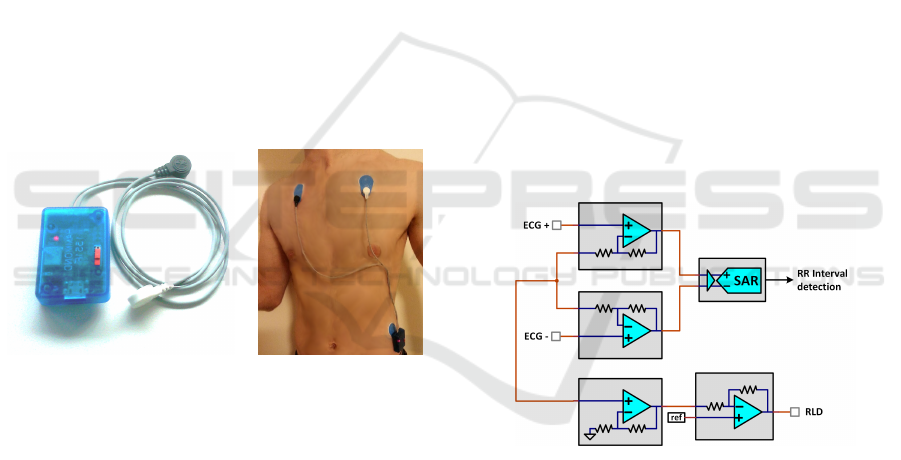
2.1 Targeted Wearable Device Overview
(a) (b)
Figure 1: Device overview (a) and example of placement on
the body using three disposable electrodes (b).
The REC Heart Activity sensor is a wearable de-
vice which has been developed to enable the continu-
ous monitoring and analysis of cardiac activity during
long-term experiments in real life conditions.
The device comprises a small electronic board
and a 300 mAh Lithium-Ion battery encapsulated in
a small plastic enclosure (50 mm x 35 mm x 15
mm) and can be connected to ECG electrodes by the
means of three snap connectors, thus the sensor is in-
tended to be connected to various electrode configu-
rations, directly on the body (Figure 1). Possible elec-
trode configurations include for example a disposable
patch of gel electrodes, or a chest belt with dry elec-
trodes, depending on the requirements regarding the
experiment conditions (resting or effort during short
periods, long-term monitoring during several days,
etc.). The electronic board includes a Bluetooth Low
Energy (BLE) interface for wireless communication,
and the sensor can be integrated in a Wireless Body
Sensor Network (WBSN). In the frame of the RE-
CAMED project, an Android application has been
developed to collect data from a WBSN composed
of various wearable sensors including the REC Heart
Activity sensor.
The electronic architecture of the board is based
on a PSoC 5LP (Cypress Semiconductors). This
mixed-signal Programmable System-on-Chip con-
sists of a Cortex M3 ARM micro-controller unit, but
also includes analog programmable functions as well
as programmable logic device (PLD) based functions.
This component can thus carry out all the steps from
the conditioning of the ECG signals to the transmis-
sion of high level heart activity indicators through
the BLE interface, including signal processing, ana-
log to digital conversion, heart beat detection, heart
rate measurement, and heart rate variability calcula-
tion. All these functions are integrated within a low-
power, single chip with a highly reduced size (8 mm
x 8 mm) as described in the next sections.
2.2 Integrated Signal Processing of
Electrocardiogram
Figure 2: ECG processing chain using internal PSoC 5LP
analog hardware components.
The amplification and digitization of ECG is done by
using the integrated and programmable analog func-
tions of the PSoC5 LP. A differential amplifier is real-
ized by combining programmable gain amplifiers and
the outputs are directly connected to a 12-bit succes-
sive approximation differential ADC (Figure 2) . Two
additional operational amplifiers used as buffer and
inverting amplifier respectively are chained to imple-
ment a right-leg drive (RLD) circuit to provide ad-
ditional common-mode noise rejection (Winter and
Webster, 1983). The overall differential gain is set to
24 and the SAR ADC has an input range set to ±1.024
V so the resolution is 20.8 µV/bit, and the signal is
sampled at 8192 samples per second.
Smart-BIODEV 2016 - Special Session on Smart Embedded Biomedical Devices for In Situ Physiological Signal Processing
304

2.3 Integrated Hardware Digital
Measurement of Heart Rate
Figure 3: RR-Interval detection chain using internal PSoC
5LP digital hardware components (PLDs).
The objective of using hardware digital components
for the measurement of Heart Rate is to benefit for
the highly reduced consumption of PLDs available
within the PSoC. Consuming processing time of the
MCU for R-peak detection would lead to a high us-
age of battery power for a real-time detection peaks
on the ECG signal at a 8192 sps sampling rate. Al-
ternatively this hardware chain have an average con-
sumption of 140 µA and enables the MCU to remains
into an idle state, as the data is also directly trans-
mitted from the analog chain to the digital chain by a
DMA channel. R-peaks detection is done by imple-
menting a digital filter and a local maximum detector
in the PSoC’s PLDs (Figure 3).
The digital filter block (DFB) acts as an ultra-low
power DSP in which is implemented a non-linear fil-
ter to enhance power in the higher frequency of ECG
signal (Pan and Tompkins, 1985). The processing
includes a double buffering of the ECG to calculate
a smoothed derivative which is then squared, and a
moving-average filter is applied on the final signal.
The local maximum detector uses an adaptive
threshold to take into account the variability of ECG
amplitude between individuals and also aver time.
The dynamic threshold T is dynamically computed
within the PLD components by an exponential filter
as in Equation 1, where β is the amplitude ratio of the
current peak detected P, and α is the smoothing factor
of the filter.
T
n+1
= α · β · P
n
+ (1 − α) · T
n
(1)
The value of a 1024 Hz up-counter is copied into
the MCU memory by a DMA channel and an interrupt
is triggered each time a peak is detected on the sig-
nal. Additionally a “fail-safe” down-counter disables
detection when false peaks have been detected until
three consecutive peaks are properly detected. The
condition of false detection is true when the variation
of RR-interval is higher than 25% of the last one. This
method guarantees reliable RR-intervals value for the
proper calculation of HRV parameters which is more
sensitive to false detection than missing values (cf.
section 2.4).
2.4 Software Calculation of Heart Rate
Variability Parameters
When the hardware detector triggers an interrupt
which wakes up the MCU, the new RR-interval is
copied into a buffer which keep in memory the values
of the last 5 minutes, the standard period for evaluat-
ing short-term HRV according to the Task Force of the
European Society of Cardiology and the North Amer-
ican Society of Pacing and Electrophysiology (Malik
et al., 1996). This signal (tachogram) buffered is then
used to calculate both time-domain and frequency-
domain parameters of HRV. The Task Force has se-
lected a large number of parameters to evaluate HRV,
from which four parameters has been retained to be
calculated in this application, based on their common
usage in the analysis of ANS activity (see Table 2 at
the end of the section).
The calculations are performed directly by the
MCU with floating point values, due to the precision
needed within these operations. This induces periods
of intensive occupation of the MCU which need to
be reduced at the minimum if one wants to optimize
consumption of the device.
2.4.1 Time-domain Parameters
The calculation of time-domain parameters of the
HRV is quite straight-forward and the two most used
parameters are computed in this application, i.e. the
standard deviation of intervals in the buffer (SDNN)
and the quadratic mean of differences between suc-
cessive intervals (RMSSD). These parameters are cal-
culated used the formulas given by Equations 2 and 3.
SDNN =
v
u
u
u
t
1
n − 1
n
∑
i=1
(RR
i
)
2
−
1
n
n
∑
i=1
RR
i
!
2
(2)
RMSSD =
v
u
u
t
1
n − 1
n−1
∑
i=1
(RR
i+1
− RR
i
)
2
!
(3)
Most devices commercially available which pro-
vide real-time HRV monitoring, calculate only one
time-domain parameter (one among the two cited),
and usually without naming it. In this application, we
Mixed Hardware and Software Embedded Signal Processing Methods for in-situ Analysis of Cardiac Activity
305

apply to provide precise information about the param-
eters calculated, whose variations can differ depend-
ing on the situation and thus modify the interpretation
of HRV regarding the ANS activity.
2.4.2 Frequency-domain Parameters
Calculation of frequency-domain parameters of HRV
requires an evaluation of power spectral density
(PSD) of the tachogram as it evaluates the distribu-
tion of energy of the signal in separated frequency
bands. The main frequency bands are usually de-
fined as ultra-low (ULF), very low (VLF), low (LF)
and high frequencies (HF) (Table 1).
Table 1: Separation of power spectral density of the
tachogram in frequency bands.
Name Frequency range
ULF ≤ 0.003 Hz
VLF 0.003-0.04 Hz
LF 0.04-0.15 Hz
HF 0.15-0.4 Hz
In this application, the method of evaluating the
PSD is critical due to the embedded electronic ar-
chitecture used in the sensor, which provides limited
resources in performance and time. As RR-intervals
vary in time, the tachogram is composed of unevenly
sampled values; thus a traditional approach for spec-
tral analysis consists of a combination of (i) an inter-
polation, in order to recover an evenly sampled signal,
and (ii) a subsequent Fast Fourier Transform (FFT) to
obtain the PSD. However this approach, depending on
the method of interpolation, the sampling rate and the
number of points, is known to introduce distortion in
the high-frequency domain where re-sampling acts as
a low-pass filter, leading to an overestimation of HRV
parameters (Clifford and Tarassenko, 2005). Also this
method is known to be very sensitive to both errors in
detection and measurement of RR-intervals as well as
missing values in the tachogram.
Another approach for spectral analysis of an un-
evenly sampled signal is the least square analysis,
commonly termed the Lomb-Scargle periodogram,
which provides (in a normalised form), the estimated
power P of the angular frequency component ω. The
estimated power is given by Equation 4, where σ =
SDNN, the standard deviation of all R-R intervals, RR
is the mean value, and τ is an angular quantity defined
by Equation 5.
P(ω) =
1
2σ
2
∑
n
i=1
(RR
i
− RR)cos(ω(t
i
− τ))
2
∑
n
i=1
cos
2
(ω(t
i
− τ))
+
∑
n
i=1
(RR
i
− RR)sin(ω(t
i
− τ))
2
∑
n
i=1
sin
2
(ω(t
i
− τ))
!
(4)
tan(2ωτ) =
∑
n
i=1
cos(2ωt
i
)
∑
n
i=1
sin(2ωt
i
)
(5)
This method, originally proposed by Lomb
(Lomb, 1976) and further elaborated by Scargle
(Scargle, 1982), was proposed as a surrogate for HRV
calculations for the first time by Shin et al. (Shin et al.,
1994) in 1994 (to the best of authors’ knowledge).
This method provides better accuracy and lower noise
levels in the estimation of the density power spectrum,
but unfortunately it also has the major drawback of in-
volving much more calculation complexity, and thus
MCU time consumption, even when the algorithm is
optimized with classical trigonometric recurrences.
Press and Rybicki (Press and Rybicki, 1989) have
proposed a much faster computation of this parame-
ter by combining the accuracy of the periodogram and
the efficiency of FFT, resulting in an algorithm which
is as fast as two FFT calculations and a N log N order
instead of N
2
. In this case the FFT is not used for
the direct evaluation of the periodogram, but rather
to calculate approximately (but to any desired preci-
sion), both main terms of Equation 4. To evaluate
trigonometric sums of the equation, which can not be
calculated with FFTs due to the unevenly spaced data,
the method involves reverse interpolations, call extir-
polation. As the interpolation evaluates one value at
an arbitrary point upon several values from a regularly
sampled function, the extirpolation evaluates several
value of a regularly sampled function from the value
of an arbitrary point. The precision, and also the dura-
tion of this evaluation depends on the number of extir-
polated points per 1/4 cycle of the highest frequency
(MACC parameter). The raw algorithm and several
values of the MACC parameter of its fast implemen-
tation have been tested, and a performance compari-
son in accuracy and gain of time is presented in the
Results section.
As stated above, the Lomb-Scargle periodogram
being dedicated to the evaluation of PSD for unevenly
signals, it is far less sensitive to missing data than FFT
where interpolation can lead to large differences de-
pending on the interpolation method. Also both meth-
ods are sensitive to false detections, therefore an ad-
ditional “fail-safe” digital circuit has been added to
the R-peak detector as described in section 2.3. This
circuit gives a higher prevalence to correct R-peak de-
tections at the cost of additional missing values.
Smart-BIODEV 2016 - Special Session on Smart Embedded Biomedical Devices for In Situ Physiological Signal Processing
306

Table 2: Summary of short-term HRV parameters calculated by the REC Heart Activity sensor.
Variable Unit Domain Description
SDNN ms Time Standard deviation of all R-R intervals
RMSSD ms Time Quadratic mean of differences between successive R-R intervals
LF/HF n.u. Frequency Ratio between LF and HF components of the PSD of all R-R intervals
LF norm % Frequency Ratio (expressed as a percentage) between LF and LF+HF
3 EVALUATION AND RESULTS
The objective of the evaluation of the HR measure-
ment method and the HRV parameters calculation
method is primarily to optimize the different parame-
ters (gain, sampling rate, ratios of the dynamic thresh-
old, extirpolation of the fast periodogram, etc.) to en-
sure that the device will provides both the mandatory
robustness and accuracy of the signals (and thus de-
rived data) for the use of the sensor in clinical ex-
periments and applications. On an other hand, it is
necessary to maintain a suitable autonomy for long-
term experiments by reducing power consumption of
the overall device. In the proposed implementation,
where the consumption of HR measurement method
is already highly optimized by the use of dedicated
hardware functions, further reduction of power con-
sumption relies on the optimization of the calculation
time of HRV parameters.
For this purpose, the REC Heart Activity sensor
was evaluated both on a workbench in laboratory con-
ditions as well as on individuals in real-life conditions
as described in the next sections.
3.1 Accuracy of HR Assessment
Accuracy of the detection of R-peaks and the mea-
surement of RR-intervals upon the ECG signal was
evaluated using a hardware generated ECG. The Ag-
ilent 33220A is function / arbitrary waveform gener-
ator which provides a cardiac waveform. The ampli-
tude, common-mode and frequency can be varied to
verify the proper operation of the device in various
conditions as those three parameters depends highly
on the environmental and physical conditions of the
individual (resting, effort), and also varies with the
change of the electrode/skin interface over time (par-
ticularly when using dry electrodes).
The error in RR-intervals measurement was cal-
culated as the mean difference between the period set
on the generator and the period measured by the sen-
sor. As the latter uses a counter with a frequency of
1024 Hz, the precision of RR-intervals measured is
0.98 ms. A dataset of 1000 RR-intervals was col-
lected where intervals’ length was linearly varied on
the generator from 400 ms (150 BPM) to 1200 ms (50
BPM), which is representative of most common heart
rates. The mean value of all difference was -0.105 ms
and the standard deviation of the differences was of
1.027 ms over all the range of RR-intervals. This dif-
ference corresponds to an error of 0.1 BPM whan HR
is 60 BPM, and 0.4 BPM when HR is 120 BPM which
is lower than the usual 1 BPM resolution in standard
devices.
3.2 Accuracy of PSD Estimation
To simulate heart rate variability and to evaluate
the accuracy of the different implementation of the
Lomb-Scargle periodogram, a known frequency mod-
ulation was applied to the ECG signal generated by
the Agilent 33220A. The base HR was set at f
base
=
1.25 Hz (75 BPM). The modulating signal was a tri-
angular shape, with a frequency f
mod
of 0.05 Hz and
an amplitude of frequency deviation f
dev
of 0.2 Hz.
As the PSD is computed over RR-intervals in units of
time (ms), the theoretical continuous function RR(t)
corresponding to the tachogram is given by Equations
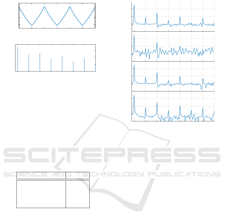
6 and 7. The time variations of this continuous and pe-
riodic signal as well as the normalized PSD are shown
on Figure 4.
x
tri
(t) = 2
2
t ∗ f
mod
−
t ∗ f
mod
+
1
2
− 1 (6)
RR(t) =
1
f
base
+ f
dev
∗ x
tri
(t)
(7)
As shown on the normalized PSD, the use of a tri-
angular shape as a modulating signal for HR has the
advantage of inducing predictable harmonics in the
PSD at multiple frequencies of the fundamental f
mod
all over the range of interest 0.015-0.4 Hz. Addition-
ally, the inverting relationship between RR-interval
values and HR breaks the vertical symmetry of the
triangular signal and thus adds even harmonics to the
odd harmonics of the original triangular shape.
It therefore possible to analyse directly PSD ob-
tains with different methods in order to compare
both quality of PSD estimation and time of calcula-
tion. For this evaluation, the original Lomb-Scargle
Mixed Hardware and Software Embedded Signal Processing Methods for in-situ Analysis of Cardiac Activity
307
Time (s)
0 10 20 30 40 50 60
RR-Interval (ms)
700
800
900
1000
Frequency (Hz)
0.05 0.1 0.15 0.2 0.25 0.3 0.35 0.4
Norm. PSD (/Hz)
10
-7
10
-5
10
-3
10
-1
Figure 4: Theoritical continuous tachogram of generated
RR-intervals and corresponding normalized PSD.
periodogram was implemented and optimized using
trigonometric recurrences (Press, 2007). The fast im-
plementation of the periodogram (Press and Rybicki,
1989) was also implemented, and tested with three
different values for the MACC factor (1, 2 and 4).
Figure 5 shows the result of the different methods
applied on RR-intervals during 5 minutes. Also Ta-
ble 3 presents the calculation time for each method
with the MCU set at its lower frequency (3 MHz) for
reducing current consumption.
Table 3: Calculation time for each method of PSD estima-
tion of RR-intervals for 5-minute long segments.
Type Time (s)
Original LP > 60
Fast LP (MACC = 4) 4
Fast LP (MACC = 2) 2.5
Fast LP (MACC = 1) 1
This results clearly shows that the original Lomb-
Scargle implementation is not usable due to the espe-
cially long time of calculation (over 1 minute). How-
ever, the fastest implementation (MACC = 1) which
takes only 1 second to calculate, adds considerable
noise to the original PSD with a level around -70 dB.
Finally the fast implementation with a MACC factor
of 2 seems to be the best compromise between calcu-
lation time and noise level as it does not excess the
level of the original one at -100 dB.
3.3 Evaluation of Power Consumption
Together with robustness and accuracy, one of the
main objectives of the implementation of mixed hard-
ware and software method for HR and HRV measure-
ment is the optimization of power consumption of the
LP (/Hz)
10
-5
10
-3
10
-1
LPF 1 (/Hz)
10
-5
10
-3
10
-1
LPF 2 (/Hz)
10
-5
10
-3
10
-1
Frequency (Hz)
0.05 0.1 0.15 0.2 0.25 0.3 0.35 0.4
LPF 4 (/Hz)
10
-5
10
-3
10
-1
Figure 5: Normalized periodogram over of a generated 300-
second buffer of RR-intervals using original Lomb-Scargle
periodogram (LP) and its fast implementation for a MACC
factor of 1,2 and 4 (LPF 1, LPF 2 and LPF 4 respectively).
REC Heart Activity Sensor. In this section we present
and discuss the result of power consumption of the
different parts of the system, composed of the analog
ECG processing, analog to digital conversion of the
signal, digital HR measurement, and software HRV
calculation. Also additional power consumption due
to wireless communication must be taken into account
to estimate the overall consumption of the system.
Table 4 summarizes the power consumption of the
different modules with the configuration used, by tak-
ing into account the duty cycle of module active time
over a period of 5 minutes. The consumption of the
RF module corresponds to a BLE connection with an
Android device where every new HR and HRV values
are sent in real time. The system is powered at 3.3
V using a linear voltage regulator having a negligible
quiescent current and a 300 mAh one-cell Lithium-
Ion battery, which enables to estimate the global au-
tonomy of the sensor device.
The total resulting current consumption leads to
a theoretical autonomy of 54 hours. This results is
already large enough for very long term monitoring
of cardiac activity during in-situ experiment. Indeed
charging the battery, thanks to embedded micro-USB
connector on the device, only less than 1 hour by us-
ing an ordinary USB charger. This can be done once
Smart-BIODEV 2016 - Special Session on Smart Embedded Biomedical Devices for In Situ Physiological Signal Processing
308

Table 4: Average current consumption of the different part
of the REC Heart Activity sensor.
Module Average current
Device base 1.83 mA
Radio module 0.82 mA
Analog Front-end 2.44 mA
Analog to digital conversion 0.25 mA
Hardware HR measurement 0.14 mA
Software HRV calculation 0.02 mA
Total 5.5 mA
every two days during a short period when the de-
vice is not used (for example it can be done during
the daily time spent in the bathroom, where the de-
vice has to be removed).
On the other hand, the results show that a impor-
tant contribution to the actual current consumption is
due to analog front end which is composed of the in-
tegrated amplifiers for the differential amplification as
well as the RLD circuit. This could be reduced by us-
ing existing discrete components which are optimized
for low-power applications and then extends further
the autonomy of the device with equal signal quality.
In conclusion, regarding the hardware HR mea-
surement and HRV calculation methods, the evalua-
tion has validated the advantage of combining avail-
able PLDs for real-time detection and measurement
of HR with an optimized method for the calculation
of short term HRV parameters, both in time and fre-
quency domains, directly on the embedded system.
4 CONCLUSION
The objective of this study was to evaluate possibil-
ities of taking advantage of a programmable system-
on-chip in order to combine optimized methods for
a complete, real-time monitoring and analysis of car-
diac activity directly on a wearable sensor. This was
done by using a PSoC5 LP, which combines :
• Integrated, programmable analog components,
which were used to build the analog ECG front-
end;
• Integrated digital filter components for a hardware
R-peak detection and RR-interval measurement;
• 32-bit ARM Cortex M3 micro-controller unit
for an embedded calculation of time-domain and
frequency-domain HRV parameters.
The main advantage of using a PSoC5 LP was to
have the entire ECG process, HR and HRV calcula-
tions fully integrated in a small, single chip. The Pan
and Tompkins’ method for R-peak detection was im-
plemented as a non-linear filter to benefits from the
ultra-low power digital filter block, combined with a
local maximum detector using a dynamic threshold
for robust detection. The Press and Rybicki’s fast
algorithm for spectral analysis was adapted to pro-
vide a better estimation of PSD by the use of method
dedicated to unvenly sampled data rather than FFTs,
with fast enough calculation time compared to the
original implementation of the Lomb-Scargle peri-
odogram. A future optimization could be the use of a
dedicated analog front-end rather than the integrated
programmable-gain amplifiers which get higher cur-
rent consumption than commercially available dis-
crete components or ECG amplifiers.
However the REC Heart Activity sensor is already
proposed as solution for a better real-time assessment
of cardiac activity by providing not only HR mea-
surement but also both time-domain and frequency-
domain HRV parameters, calculated according to in-
ternational standards for HRV analysis.
Moreover this device can be used within a wire-
less body sensor network, together with the sensors
designed in the frame of the RECAMED project, as
well as a software platform on smartphone for col-
lecting, storing, and passing on data securely. This
WBSN is proposed as a solution for the increasing
clinical need of automated collection of health data
from multiple patients, both inside and outside of a
medical environment (hospital or nursing home).
ACKNOWLEDGEMENTS
The REC Heart Activity sensor is developed in the
frame of the RECAMED project, funded by the
BQR’s program at INSA Lyon.
REFERENCES
Altini, M., Polito, S., Penders, J., Kim, H., Van Helleputte,
N., Kim, S., and Yazicioglu, F. (2011). An ecg patch
combining a customized ultra-low-power ecg soc with
bluetooth low energy for long term ambulatory moni-
toring. In Proceedings of the 2nd Conference on Wire-
less Health, page 15. ACM.
Chen, Y.-H., Op de Beeck, M., Vanderheyden, L., Mi-
hajlovic, V., Grundlehner, B., and Van Hoof, C.
(2013). Comb-shaped polymer-based dry electrodes
for eeg/ecg measurements with high user comfort.
In Engineering in Medicine and Biology Society
(EMBC), 2013 35th Annual International Conference
of the IEEE, pages 551–554. IEEE.
Mixed Hardware and Software Embedded Signal Processing Methods for in-situ Analysis of Cardiac Activity
309

Clifford, G. D. and Tarassenko, L. (2005). Quantifying er-
rors in spectral estimates of hrv due to beat replace-
ment and resampling. Biomedical Engineering, IEEE
Transactions on, 52(4):630–638.
Go, A. S., Mozaffarian, D., Roger, V. L., Benjamin, E. J.,
Berry, J. D., Blaha, M. J., Dai, S., Ford, E. S., Fox,
C. S., Franco, S., et al. (2014). Heart disease and
stroke statistics–2014 update: a report from the amer-
ican heart association. Circulation, 129(3):e28.
Lomb, N. R. (1976). Least-squares frequency analysis of
unequally spaced data. Astrophysics and space sci-
ence, 39(2):447–462.
Malik, M., Bigger, J. T., Camm, A. J., Kleiger, R. E.,
Malliani, A., Moss, A. J., and Schwartz, P. J. (1996).
Heart rate variability standards of measurement, phys-
iological interpretation, and clinical use. European
heart journal, 17(3):354–381.
Massot, B., Noury, N., Gehin, C., and McAdams, E. (2013).
On designing an ubiquitous sensor network for health
monitoring. In 2013 IEEE 15th International Confer-
ence on e-Health Networking, Applications and Ser-
vices (Healthcom) (IEEE Healthcom 2013), Lisbon,
Portugal.
McAdams, E., Krupaviciute, A., Gehin, C., Grenier, E.,
Massot, B., Dittmar, A., Rubel, P., and Fayn, J. (2011).
Wearable sensor systems: The challenges. In Engi-
neering in Medicine and Biology Society,EMBC, 2011
Annual International Conference of the IEEE, pages
3648 –3651.
Pan, J. and Tompkins, W. (1985). A real-time qrs detection
algorithm. IEEE transactions on bio-medical engi-
neering, 32(3):230–236.
Press, W. H. (2007). Numerical recipes 3rd edition: The art
of scientific computing. Cambridge university press.
Press, W. H. and Rybicki, G. B. (1989). Fast algorithm
for spectral analysis of unevenly sampled data. The
Astrophysical Journal, 338:277–280.
Romero, I., Grundlehner, B., and Penders, J. (2009). Robust
beat detector for ambulatory cardiac monitoring. In
Engineering in Medicine and Biology Society, 2009.
EMBC 2009. Annual International Conference of the
IEEE, pages 950–953. IEEE.
Scargle, J. D. (1982). Studies in astronomical time se-
ries analysis. ii-statistical aspects of spectral analysis
of unevenly spaced data. The Astrophysical Journal,
263:835–853.
Sch
¨
afer, A. and Vagedes, J. (2013). How accurate is pulse
rate variability as an estimate of heart rate variabil-
ity?: A review on studies comparing photoplethysmo-
graphic technology with an electrocardiogram. Inter-
national journal of cardiology, 166(1):15–29.
Shin, K., Minamitani, H., Onishi, S., Yamazaki, H., and
Lee, M. (1994). The direct power spectral estimation
of unevenly sampled cardiac event series. In Engi-
neering in Medicine and Biology Society, 1994. En-
gineering Advances: New Opportunities for Biomedi-
cal Engineers. Proceedings of the 16th Annual Inter-
national Conference of the IEEE, pages 1254–1255.
IEEE.
Van Hoof, C. and Penders, J. (2013). Addressing the health-
care cost dilemma by managing health instead of man-
aging illness: an opportunity for wearable wireless
sensors. In Proceedings of the Conference on De-
sign, Automation and Test in Europe, pages 1537–
1539. EDA Consortium.
Winter, B. B. and Webster, J. G. (1983). Driven-right-leg
circuit design. Biomedical Engineering, IEEE Trans-
actions on, 30(1):62–66.
Smart-BIODEV 2016 - Special Session on Smart Embedded Biomedical Devices for In Situ Physiological Signal Processing
310
