
Enriching Model Execution with Feedback to Support Testing of
Semantic Conformance between Models and Requirements
Design and Evaluation of Feedback Automation Architecture
Gayane Sedrakyan and Monique Snoeck
Department of Decision Sciences and Information Management, Research Center for Management Informatics,
KU Leuven, Leuven, Belgium
Keywords: Model Driven Development, Simulation Feedback, Conceptual Modeling, Rapid Prototyping, Model
Testing / Validation, Feedback Automation.
Abstract: Model Driven Development (MDD) has traditionally been used to support model transformations and code
generation. While plenty of techniques and tools are available to support modeling and transformations, tool
support for checking the model quality in terms of semantic conformance with respect to the domain
requirements is largely absent. In this work we present a model verification and validation approach based
on model-driven feedback generation in a model-to-code transformation. The transformation is achieved
using a single click. The generated output of the transformation is a compiled code which is achieved by a
single click. This also serves as a rapid prototyping instrument that allows simulating a model (the terms
prototyping and simulation are thus used interchangeably in the paper). The proposed feedback
incorporation method in the generated prototype allows linking event execution in the generated code to its
causes in the model used as input for the generation. The goal of the feedback is twofold: (1) to assist a
modeler in validating semantic conformance of a model with respect to a domain to be engineered; (2) to
support the learning perspective of less experienced modelers (such as students or junior analysts in their
early career) by allowing them to detect modeling errors that result from the misinterpreted use of modeling
language constructs. Within this work we focus on conceptual and platform independent models (PIM) that
make use of two prominent UML diagrams – a class diagram (for modeling the structure of a system) and
multiple interacting statecharts (for modeling a system’s dynamic behavior). The tool has been used in the
context of teaching a requirements analysis and modeling course at KU Leuven. The proposed feedback
generation technique has been constantly validated by means of “usability” evaluations, and demonstrates a
high level of self-reported utility of the feedback. Additionally, the findings of our experimental studies also
show a significant positive impact of feedback-enabled rapid prototyping method on semantic validation
capabilities of novices. Despite our focus on specific diagramming techniques, the principles of the
approach presented in this work can be used to support educational feedback automation for a broader
spectrum of diagram types in the context of MDD and simulation.
1 INTRODUCTION
The software development process involves the
translation of information from one form to another
(e.g. from customer needs to requirements, to
architecture, to design and to code). Because this
process is human-based, mistakes are likely to occur
during the translation steps (Walia and Carver,
2009). The vision of Model Driven Development
(MDD) of software introduces automation in the
software development process, which results in
reduced human intervention. MDD is a development
methodology that uses models, meta-models, and
automated model transformations to achieve
automated code generation (Stahl et al., 2006).
Despite the variety of tools for modeling and code
generation, tool support for verifying and validating
the semantic conformance of models (i.e. the quality
of transformation input) with requirements is largely
lacking. Conformance mismatch can result from
errors in different steps of a process: modeling,
model-to-model transformation, or model-to-code
transformation. In this work, we target at errors
resulting from a semantic mismatch that occur
14
Sedrakyan, G. and Snoeck, M.
Enriching Model Execution with Feedback to Support Testing of Semantic Conformance between Models and Requirements - Design and Evaluation of Feedback Automation Architecture.
DOI: 10.5220/0005841800140022
In Proceedings of the International Workshop on domAin specific Model-based AppRoaches to vErificaTion and validaTiOn (AMARETTO 2016), pages 14-22
ISBN: 978-989-758-166-3
Copyright
c
2016 by SCITEPRESS – Science and Technology Publications, Lda. All rights reserved

during the modeling process which are caused by
reasons such as misunderstanding of requirements,
misinterpreting modeling constructs, lack of domain
experience of a human modeler, etc. In related
research this type of validity issues are referred to as
semantic validity. The semantic validity of a model
is an important aspect of model quality, which refers
to the level to which the statements in a model
reflect the real world domain in a valid and complete
way (Lindland et al., 1994). Validation of a model
quality involves many different dimensions related
to physical artefacts and knowledge artefacts
(Nelson et al., 2012). Because semantic quality
cannot be directly assessed but needs to be assessed
by a human, it has to go through the knowledge
layer, which therefore results in a complex cognitive
process involving other quality types. On the
knowledge side, assessing semantic quality requires
an appropriate level of domain knowledge, model
knowledge, language knowledge and representation
knowledge (Nelson et al., 2012), hence requiring
view quality (understanding the domain),
pedagogical quality (understanding the modeling
concepts), linguistic quality (understanding the
graphical notation) and pragmatic quality
(understanding a model) (Nelson et al., 2012). In
particular, pragmatic quality captures the extent to
which the stakeholder completely and accurately
understands the statements in the representation that
are relevant to them.
In this work we propose a novel MDD approach
that embeds a feedback generation mechanism into a
model-to-code transformation to achieve a feedback-
enabled transformation output. By enabling a fully
functional output the method also serves as a rapid
prototyping and simulation instrument. This allows
assessing the generated prototype (simulation
results) with respect to the desired outcome. In case
of a semantic mismatch the desired outcome can be
achieved through a trial and error correction process
by means of modification, regeneration and
verification loops. The goal of the incorporated
feedback in the simulation loop is to facilitate the
process of verification of semantic validity of the
model provided as a transformation input. The
feedback is generated as an explanation to error
messages when testing and validating a model. The
errors include event execution failures that result
from constraint violations, which are regarded as
invalid actions from the domain perspective. We
make use of two type of feedback formats: (1)
explanation of the causes for the errors (constraint
violations) represented in textual format and (2)
graphical visualization that links the execution
results to their causes in a model. We further present
a template-based model driven development
technique for realization of such feedback.
For a modeling language we opted for UML as it
is the current standard widely used in the research
and industry. The diagramming tool we used is
JMermaid, a tool built based on MERODE
methodology (Snoeck, 2014). The tool uses a
combination of two prominent UML diagramming
techniques: a class diagram and statecharts (also
called finite state machines). The output of the
modeling tool is an executable platform independent
domain model (PIM) that is readily transformable to
code using a one click MDD-based code generation
approach (Sedrakyan and Snoeck, 2013b) which
makes it particularly suitable for the goals of this
work. Our choice of the diagramming techniques is
motivated by the fact that class diagram and
statecharts are both in the kernel of “essential”
UML (i.e. diagrams that are highly used) with the
highest usability ranks by practitioners and
educators from software industry and academic field
(Erickson and Siau, 2007). Furthermore these are
also among the top used diagrams present in the
context of educational material such as books, tools,
courses and tutorials (with percentages of 100%
(class diagram) and over 96% (statecharts) (Reggio
et al., 2013). Because of their high cognitive and
structural complexity (Cruz-Lemus et al., 2008;
Cruz-Lemus et al., 2010) both techniques are also
among the most complex diagramming techniques:
UML class diagram ranks the highest in complexity
among the structural diagrams (Siau and Cao, 2001)
followed by statecharts among the dynamic
diagrams (Carbone and Santucci, 2002; Cruz-Lemus
et al., 2009; Cruz-Lemus et al., 2007; Genero et al.,
2003).
While our previous papers focused on presenting
the results of assessing the effectiveness of the
feedback-enabled prototype (output of the PIM-to-
code transformation simulation tool) with respect to
its capability of affecting semantic validation
process of models (Sedrakyan and Snoeck, 2012;
2013a; 2014a; 2014b; 2015; Sedrakyan et al., 2014),
in this work we present the principles for setting up
the automated feedback during the model-to-code
transformation process. The research question
addressed in this paper is: “What is required to set
up an automated simulation feedback that facilitates
the testing of the semantic validity of a model and
how can such feedback be (technically) realized ?”
This paper describes the architectural design of
the feedback automation method. The resulting
artefact was evaluated by means of yearly
Enriching Model Execution with Feedback to Support Testing of Semantic Conformance between Models and Requirements - Design and
Evaluation of Feedback Automation Architecture
15
evaluations of self-reported “usability”. Besides this
self-reported utility, the utility of the automated
feedback approach also has been evaluated through
experimental studies. Aggregated results of 6
empirical/experimental studies in the context of two
master-level courses from two different study
programs at KU Leuven (Sedrakyan et al., 2014) are
briefly presented.
The results presented in this paper contribute to
the research on 1. model-driven development with
respect to its applicability to feedback generation, 2.
simulation theory with respect to addressing the
difficulties in interpretation of simulation results
(Banks, 1999). Furthermore, not many studies can
be found in the domain of feedback automation. In
the context of education the results contribute to the
research on 3. automation methods for (learning
process-oriented) feedback which is in turn
intertwined with self-regulative learning. Despite
our focus on specific diagramming techniques, the
approach presented in this work can be
applied/enhanced to support feedback automation
for a broader spectrum of diagram types. The
technique can also be used to support a
teaching/learning context for courses that use
modeling. This may include courses such as system
architecture and design, databases, software
engineering, prototyping and testing of
requirements, model driven development, etc.
2 METHODOLOGY
The feedback is realized using MDD technique. The
approach was built following the principles of
Design Science in Information Systems research
which proposes two main guidelines 1. building and
2. (re)evaluating novel artefacts to help
understanding and solving knowledge problems
(Hevner et al., 2004). We first present the required
components and the architectural design for building
feedback. We then propose a template-based model
driven development technique for realization of the
proposed feedback.
To test and evaluate the proposed design with
respect to its subjective perceptions of usability by
users (perceived easiness of use, perceived utility,
preference and satisfaction) yearly evaluations were
performed. Ease of use and usefulness are
widespread and validated acceptance beliefs from
the Technology Acceptance Model (Davis, 1989;
Davis et al., 1989; Venkatesh et al., 2003), referring
to the required effort to interact with a technology
and its efficiency and effectiveness respectively. We
used the concept of preference as another success
dimension, as proposed by (Hsu and Lu, 2007) and
(Bourgonjon et al., 2010). Preference is defined as
“the positive and preferred choice for the continued
use of simulation tool in the classroom”. User
satisfaction is another key success measure that has
been defined as the feelings and attitudes that stem
from aggregating all the efforts and benefits that an
end user receives from using an system (Ives et al.,
1983; Wixom and Todd, 2005). Thereto a
questionnaire was used including three questions per
measurable dimension, each of which measured with
a six-position Likert-type scale. The impact of pro-
social behavior (Mitchell and Jolley, 2012) was
isolated by ensuring the anonymity of participants,
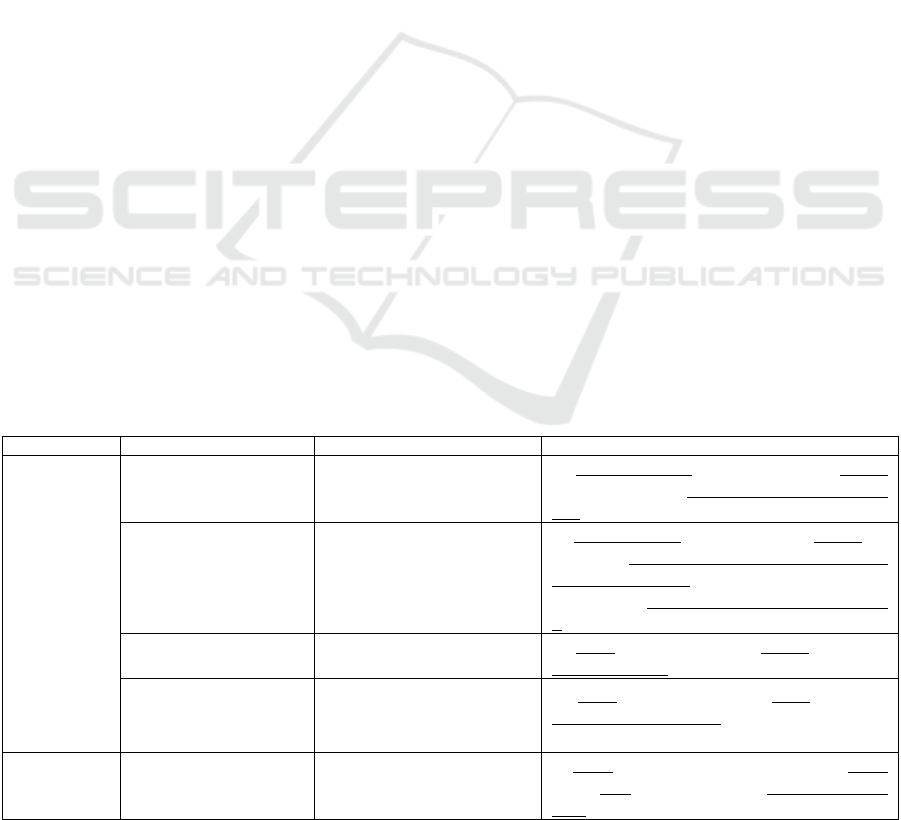
Table 1: Examples of model elements used to construct feedback for class diagram and statecharts.
Diagram Constraint type Error type Explanation & model properties
Class diagram
Cardinality of minimum 1 Create-event execution failure
an object of type A is attempted to be created
without choosing an object of type B it is associated
with
Cardinality of maximum 1 Create-event execution failure
an object of type A is attempted to be created for
which an object of type B associated with a
cardinality of max 1 is chosen which already has
been assigned another instance of an object of type
A
Referential integrity for
creation dependency
Create-event execution failure
an object is attempted to be created before the
objects it refers to were created
Referential integrity for
restricted delete
End-event execution failure
an object is attempted to be ended before its
“living” referring objects (objects that did not reach
the final state of their lifecycle) are ended
Statechart
Sequence constraint Event execution failure
an event is attempted to be executed for an object
whose state does not enable a transition for that
event
AMARETTO 2016 - International Workshop on domAin specific Model-based AppRoaches to vErificaTion and validaTiOn
16
i.e. not disclosing any identifiable information in the
questionnaire. Reliability and validity of the
acceptance measures were assessed by factor
analysis using SPSS.
3 WHAT IS REQUIRED TO SET
UP A MODEL-DRIVEN
FEEDBACK?
In this chapter we present the architectural design of
the automated feedback approach. Thereto we
identify the model elements used to set up a model-
driven feedback. According to (Nelson et al., 2012),
in the conceptual modeling quality framework each
framework element can be considered as a set of
statements. Model quality is assessed by comparing
two such sets, goals being completeness and
validity. For semantic quality, completeness is
achieved if the physical representation (the model)
contains all the statements of the domain, and
validity is achieved if what is true or false according
to the model is respectively also true or false
according to the domain rules.
Model simulation can be used to assess model
completeness by simply verifying the presence of
desired functionality in the prototype. Assessing the
validity of the model requires verifying the
truthfulness of a statement in the prototype. In other
words, if something should be allowed according to
domain rules, then this should be allowed according
to the model as well, and if something is forbidden
according to domain rules, then a corresponding
constraint should be included in the model. To verify
validity, a modeler needs to define test scenarios and
define an oracle (desired outcome) for each scenario
according to the domain rules. The results of the
execution of the test scenario are compared to the
oracle to determine the semantic correspondence
between model and domain. While novice modelers
seem at ease with using a fast prototyping approach
for the verification of model completeness, we
witnessed that novice modelers have difficulties in
understanding why a test scenario fails and relating
the cause of the failure to model constructs.
Test scenario failure finds its origins in
constraint violation. For example, if a course can be
attributed to at most one teacher, then assigning a
second teacher to a course will result in a constraint
violation and a failed test scenario. Therefore, the
first step in our architectural design includes the
identification of the constraints that are supported by
a diagram type. Next, the typology of errors with
respect to the constraint types are specified. We also
need to identify the diagram properties that take part
in those constraints. The error type can be described
as a constraint violation scenario. The error type
contains a reference to the violated constraint type
and also encapsulates the properties that participate
in the context of the event execution and those that
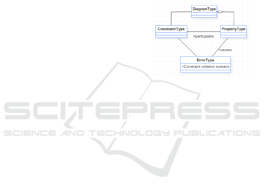
cause the error (execution failure). Figure 1 below
depicts the generic meta-model on how error types
are related to the corresponding model elements.
Figure 1: Model-elements used for a feedback.
As mentioned earlier in this paper we realize our
approach in the context of one specific type of
models, namely, conceptual models, that combine
structural and behavioral aspects of a system. The
modeling approach uses a combination of a class
diagram (to realize the structural aspects) and
multiple interacting statecharts (to support a
system’s dynamics). In the class diagram,
constraints are captured as cardinality constraints
(mandatory one, maximum one) and referential
integrity constraints (creation dependency and
restricted delete). In the case of a statechart,
constraints are captured as sequence constraints. For
each of these constraints, a corresponding error type
and explanations used for feedback can be
constructed as shown in Table 1. Explanations
include model properties (underlined in column
“Explanation & model properties”).
4 HOW THE APPROACH CAN BE
REALIZED: INCLUSION AND
GENERATION OF FEEDBACK
The feedback generation mechanism is handled by
inclusion of a feedback generation package in the
output of the model-to-code transformation and is
illustrated by the conceptual model shown in Figure
Enriching Model Execution with Feedback to Support Testing of Semantic Conformance between Models and Requirements - Design and
Evaluation of Feedback Automation Architecture
17
2. This package is responsible for 1. capturing the
execution errors (failures) and mapping them with
corresponding causes; 2. identifying the causing
model properties as well as those being
involved/affected; 3. matching the causes with
relevant feedback template for a textual feedback; 4.
generating feedback dialogs with the textual
explanation and 5. further extending the textual
explanation with its graphical visualization. In the
model-to-code transformation the event execution
process is supported by the event handler which is
responsible for the transaction logic specified by a
model. The role of the event handler is to check the
success and failure scenarios according to pre-
conditions specified in a diagram type. Constraint
support is realized by means of the pre-condition
checks. If the pre-condition checks are successful
the transactions are further executed. Error messages
are generated in case of failed precondition checks.
The model-to-code transformation is presented in
our previous work (Sedrakyan and Snoeck, 2013b)
and, as it is not the core subject of this paper, the
transformation process therefore will not be covered
in detail. We will however refer to some aspects of
the model-to-code transformations that are relevant
for feedback generation. This includes the notion of
a parser and Data Access Objects (DAO) in the
generated transformation. DAOs provide a
simplified access to model properties stored in a
database layer of the transformed code (e.g. key-
value maps containing a collection of object
properties such as a name, collections of attributes,
events, dependencies, states, etc.) which are also
used for feedback purposes. These properties are
constructed during the transformation process using
a parser and Apache Velocity Templates
(http://velocity.apache.org/) and are accessible in the
final code. In the generated application the execution
failures are implemented as exceptions. The
exception handler contains the cause of the
exception such as a reference to the corresponding
constraint type along with the model properties
involved in the constraint violation in a lightweight
data-interchange format (comma separated string).
The exception handler identifies the exception type
and in case a model related execution failure is
detected (there can be code related exceptions too)
further links to the corresponding error processor
responsible for model related errors. The error
processor further derives the necessary properties
error message data stream, converts them into
appropriate formats and forwards to the feedback
processor. The feedback processor uses a feedback
template to provide a textual explanation on the
corresponding parts of the diagram along with the
properties of a diagram causing the execution failure
as well as those being involved/affected. Sample
textual feedback templates are presented in Figure 3
and Figure 4.
Using the model parser the coordinates of model
properties from the GUI model of a diagram are
passed to a 2D graphics object. The parser is used to
access any other model properties that are required
to provide a hint for a possible correction scenario
(e.g. if an event execution fails due to an object
state, the state(s) in which theexecution is allowed
Figure 2: Feedback generation model.
AMARETTO 2016 - International Workshop on domAin specific Model-based AppRoaches to vErificaTion and validaTiOn
18
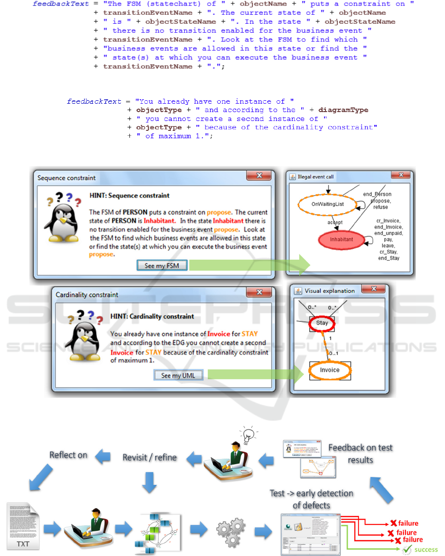
Figure 3: Sample textual feedback template for a sequence constraint violation.
Figure 4: Sample textual feedback template for a cardinality constraint violation.
Figure 5: Sample generated textual and graphical feedback for a UML class diagram and a finite state machine (FSM).
Figure 6: Positioning of the feedback in the modeling and validation process.
are used to construct a hint). The 2D graphics object
is used to access the coordinate, color and font
management system of the buffered image (an image
with an accessible buffer of image data) of a
diagram. This allows to highlight the parts of the
diagram that contains the constraint that causes the
Enriching Model Execution with Feedback to Support Testing of Semantic Conformance between Models and Requirements - Design and
Evaluation of Feedback Automation Architecture
19

error as well as to visualize the suggested hints for
the correction of the error. The color scheme is
consistent with the textual feedback which makes it
easier to trace between the textual explanation and
its graphical visualization. Sample generated textual
and corresponding graphical feedback is presented
in Figure 5.
The architecture of the proposed realization
model also allows the feedback generation package
to be easily plugged in/out in the final output. The
exception handler can serve as a (dis)connection
gate.
5 LOCATING THE FEEDBACK
IN THE SEMANTIC
VALIDATION PROCESS
In terms of positioning the proposed feedback
technique with respect to the modeling and semantic
validation process, the following sequence is implied
(see Figure 6): the user starts with analyzing a
textual description of requirements. S/he will then
transform the requirements into a conceptual model
containing both the static and dynamic
representations of a system. At any step during the
modeling process the user can simulate the model by
means of prototype generation. The prototype is then
used to test a model in terms of its semantic
conformance with the requirements. The model is
revisited/refined if semantic errors are detected. The
feedback is intended to facilitate the interpretation of
the causes of the detected errors. Such repetitive
trial/error loops will also allow to reflect on the
requirements in terms of detection of ambiguous,
missing or contradictory requirements.
6 ASSESSING THE FEEDBACK
DESIGN
User acceptance of the feedback-enabled model-to-
code transformation tool was repeatedly evaluated in
the course of several years of usage. The students
found the tool useful and preferred its use (mean
scores above 4.5 in six-position Likert-type scale).
User satisfaction, preference, perceived usefulness
and perceived ease of use were evaluated resulting
respectively on average of 4.77, 4.78, 4.78 and 4.68
(with Cronbach Alpha above 0.84 and factor
loadings per item above 0.86). The highest score in
the anonymous evaluations was attributed by
students to the incorporated feedback in the
prototype (5.58 on average). Additionally, the
effectiveness of the incorporated feedback in the
context of code generation (simulation) and its use
in the process of semantic validation of models was
experimentally evaluated. The findings of six
empirical experimental studies (N = 201) showed a
significant positive impact of the inclusion of the
feedback on the semantic validation process of
novices resulting in the average magnitude of effect
of 2.33 out of 8 for validating the structural
consistency (class diagram) and 4 out of 8 for
validating the behavioral consistency (statecharts)
and the consistency of behavioral aspects with the
structural view of a system (contradicting
constraints). The reader is referred to (Sedrakyan
and Snoeck, 2012; 2013a; 2014a; 2014b; 2015;
Sedrakyan et al., 2014) for more details on these
experimental evaluations.
7 CONCLUSION
In this work we presented a feedback automation
technique that allows enriching a model-execution
environment with automated feedback with the
purpose to assist novice modelers in the task of
validating the semantic quality of a model. The
feedback automation technique uses a model-driven
development approach combined with template-
based generation to incorporate a textual and visual
feedback in the transformation output. The feedback
approach scored very high on perceived utility by
novice modelers. This self-reported utility was
complemented by investigating the effectiveness of
such feedback with empirical/experimental studies.
The feedback was observed to stimulate self-
regulated learning resulting in significantly
improved learning outcomes. The utility and
effectiveness of the proposed approach suggest that
the same approach can be considered for application
of the proposed automated feedback method outside
the domain of conceptual modeling to provide
feedback for a broader spectrum of diagramming
techniques in a broader learning context such as
databases, programming, model driven development
and other courses. To advance the research further
certain limitations should be also considered. The
main limitation includes the fact that the approach
requires a modeling environments that provides
executable outputs (such as MERODE), i.e. models
that can be readily transformed to code.
The work presented in this paper can be
expanded along several directions, such as:
AMARETTO 2016 - International Workshop on domAin specific Model-based AppRoaches to vErificaTion and validaTiOn
20

1. expanding the framework towards a generic
feedback framework with a support for a broader
spectrum of diagrams.
2. exploring advanced feedback mechanisms, such
as personalization, using adaptive systems and
learning reinforcement algorithms. This
perspective is additionally supported by the
logging functionality of the tool allowing to
observe modeling and learning processes
(Sedrakyan et al., 2014).
3. exploring interactive feedback mechanisms to
guide a model correction process by also
highlighting the effects of changes made in the
model during the correction process.
REFERENCES
Banks, J. (1999). Introduction to simulation. Paper
presented at the Proceedings of the 31st conference on
Winter simulation: Simulation-a bridge to the future,
Volume 1.
Bourgonjon, J., Valcke, M., Soetaert, R., & Schellens, T.
(2010). Students’ perceptions about the use of video
games in the classroom. Computers & Education,
54(4), 1145-1156.
Carbone, M., & Santucci, G. (2002). Fast&&Serious: a
UML based metric for effort estimation. Paper
presented at the Proceedings of the 6th ECOOP
workshop on quantitative approaches in object-
oriented software engineering (QAOOSE’02).
Cruz-Lemus, J. A., Genero, M., Manso, M. E., Morasca,
S., & Piattini, M. (2009). Assessing the
understandability of UML statechart diagrams with
composite states—A family of empirical studies.
Empirical Software Engineering, 14(6), 685-719.
Cruz-Lemus, J. A., Genero, M., Morasca, S., & Piattini,
M. (2007). Using practitioners for assessing the
understandability of UML statechart diagrams with
composite states Advances in Conceptual Modeling–
Foundations and Applications (pp. 213-222):
Springer.
Cruz-Lemus, J. A., Genero, M., & Piattini, M. (2008).
Using controlled experiments for validating uml
statechart diagrams measures Software Process and
Product Measurement (pp. 129-138): Springer.
Cruz-Lemus, J. A., Maes, A., Genero, M., Poels, G., &
Piattini, M. (2010). The impact of structural
complexity on the understandability of UML statechart
diagrams. Information Sciences, 180(11), 2209-2220.
Davis, F. D. (1989). Perceived Usefulness, Perceived Ease
of Use, and User Acceptance of Information
Technology. MIS Quarterly, 13(3), 319-340. doi:
10.2307/249008
Davis, F. D., Bagozzi, R. P., & Warshaw, P. R. (1989).
User acceptance of computer technology: a
comparison of two theoretical models. Management
science, 35(8), 982-1003.
Erickson, J., & Siau, K. (2007). Can UML Be Simplified?
Practitioner Use of UML in Separate Domains. Paper
presented at the Proceedings of the 12th Workshop on
Exploring Modeling Methods for Systems Analysis
and Design (EMMSAD'07), held in conjunction with
the 19th Conference on Advanced Information
Systems (CAiSE'07),Trondheim, Norway.
Genero, M., Miranda, D., & Piattini, M. (2003). Defining
metrics for UML statechart diagrams in a
methodological way Conceptual Modeling for Novel
Application Domains (pp. 118-128): Springer.
Hevner, A., R., March, S. T., Park, J., & Ram, S. (2004).
Design science in information systems research. MIS
Quarterly, 28(1), 75-105.
Hsu, C.-L., & Lu, H.-P. (2007). Consumer behavior in
online game communities: A motivational factor
perspective. Computers in Human Behavior, 23(3),
1642-1659.
Ives, B., Olson, M. H., & Baroudi, J. J. (1983). The
measurement of user information satisfaction.
Communications of the ACM, 26(10), 785-793.
Lindland, O. I., Sindre, G., & Solvberg, A. (1994).
Understanding quality in conceptual modeling.
Software, IEEE, 11(2), 42-49.
Mitchell, M. L., & Jolley, J. M. (2012). Research design
explained: Cengage Learning.
Nelson, H. J., Poels, G., Genero, M., & Piattini, M.
(2012). A conceptual modeling quality framework.
Software Quality Journal, 20(1), 201-228. doi:
10.1007/s11219-011-9136-9
Reggio, G., Leotta, M., Ricca, F., & Clerissi, D. (2013).
What are the used UML diagrams? A Preliminary
Survey. Paper presented at the EESSMOD@
MoDELS.
Sedrakyan, G., & Snoeck, M. (2012). Technology-
enhanced support for learning conceptual modeling
Enterprise, Business-Process and Information Systems
Modeling (pp. 435-449): Springer.
Sedrakyan, G., & Snoeck, M. (2013a). Feedback-enabled
MDA-prototyping effects on modeling knowledge
Enterprise, Business-Process and Information Systems
Modeling (pp. 411-425): Springer.
Sedrakyan, G., & Snoeck, M. (2013b). A PIM-to-Code
requirements engineering framework. Paper presented
at the Proceedings of Modelsward 2013-1st
International Conference on Model-driven
Engineering and Software Development-Proceedings.
Sedrakyan, G., & Snoeck, M. (2014a). Do we need to
teach testing skills in courses on requirements
engineering and modelling? Paper presented at the
CEUR Workshop Proceedings.
Sedrakyan, G., & Snoeck, M. (2014b). Lightweight
semantic prototyper for conceptual modeling
Advances in Conceptual Modeling (pp. 298-302):
Springer.
Sedrakyan, G., & Snoeck, M. (2015). Effects of
Simulation on Novices’ Understanding of the Concept
of Inheritance in Conceptual Modeling Advances in
Conceptual Modeling (pp. 327-336): Springer.
Enriching Model Execution with Feedback to Support Testing of Semantic Conformance between Models and Requirements - Design and
Evaluation of Feedback Automation Architecture
21

Sedrakyan, G., Snoeck, M., & De Weerdt, J. (2014).
Process mining analysis of conceptual modeling
behavior of novices–empirical study using JMermaid
modeling and experimental logging environment.
Computers in Human Behavior, 41, 486-503.
Sedrakyan, G., Snoeck, M., & Poelmans, S. (2014).
Assessing the effectiveness of feedback enabled
simulation in teaching conceptual modeling.
Computers & Education, 78, 367-382.
Siau, K., & Cao, Q. (2001). Unified Modeling Language
(UML)-a complexity analysis. Journal of Database
Management, 12(1), 26.
Snoeck, M. (2014). Enterprise Information Systems
Engineering: The MERODE Approach: Springer.
Stahl, T., Voelter, M., & Czarnecki, K. (2006). Model-
driven software development: technology, engineering,
management: John Wiley & Sons.
Venkatesh, V., Morris, M. G., Davis, G. B., & Davis, F.
D. (2003). User acceptance of information technology:
Toward a unified view. MIS Quarterly, 27(3).
Walia, G. S., & Carver, J. C. (2009). A systematic
literature review to identify and classify software
requirement errors. Information and Software
Technology, 51(7), 1087-1109.
Wixom, B. H., & Todd, P. A. (2005). A theoretical
integration of user satisfaction and technology
acceptance. Information systems research, 16(1), 85-
102.
AMARETTO 2016 - International Workshop on domAin specific Model-based AppRoaches to vErificaTion and validaTiOn
22
