
Modeling and Analysis of Automotive Systems: Current Approaches and
Future Trends
Paolo Giusto
1
, Ramesh S.
2
and Sudhakaran M.
2
1
General Motors, Palo Alto, U.S.A.
2
General Motors, Warren, U.S.A.
Keywords:
Model-based Development, Software Product Lines, Embedded Control Systems, Virtual Development.
Abstract:
The fierce competition among automotive manufacturers in introducing Advanced Driver Assist Systems
(ADAS) and autonomous features has led to the explosive growth of the Electrical/Electronics (E/E) assets,
including Software, in today’s and future vehicles. The resource demand and quality requirements of these as-
sets has increased consequently. Rigorous methodologies and tools are required for developing the E/E assets
to meet the quality demands of these assets. This paper summarizes the current practices used in the indus-
try for managing the development of these assets and discusses the future trends. The summary includes the
description of three development strategies that are becoming important and critical, which are Model-driven
Feature Development, Product Line Approach and Virtual Development and Integration of E/E architectures.
1 INTRODUCTION
After a modest start in the early 70s, electrification of
automobiles has grown leaps and bounds over the last
few decades; it now appears to take over the industry
as evidenced both by some electronic and software
giants exploring the possibility of building the next
generation autonomous vehicles, and some new play-
ers entering the market. In addition, there has been an
increased focus on Advanced Drive Assist Systems
(ADAS) in recent times. This has resulted in an ex-
plosion of active and passive safety features, realized
by electronics and software, driving the competition
among the manufacturers and tier one suppliers in the
industry.
Today’s vehicle is a complex and heterogeneous
system of systems, containing multiple embedded
systems of different characteristics. For example, the
powertrain sub-system is a deeply embedded mix-
ture of continuous and discrete control system, the
body control system is a state based discrete reactive
system, and the infotainment system is a non-real-
time system requiring an open and flexible platform.
With the emergence of automotive safety standards
such as ISO 26262 (ISO26262, 2011), different lev-
els of safety – the Automotive Safety Integrity Levels
(ASIL) – are applied to different subsystems in the ve-
hicle depending upon the risks associated with them.
In addition, the open platform requirement of info-
tainment systems and the various (intra- and inter-)
communication interfaces, are also raising the secu-
rity risks, causing a major concern to the industry.
The Electrical/Electronic (E/E) architecture in
modern day cars amounts to million lines of soft-
ware, hundreds of sensors, tens of electronic control
units (ECU), a handful of network buses, and miles
of wires distributing power and control signals to the
ECUs. The E/E architecture directly and indirectly
impacts vehicles CO2 emissions and fuel economies
– directly as wires impact the weight of vehicle and
indirectly as the electrical loads of the vehicle (e.g.,
HVAC) may determine higher or lower miles per gal-
lon (mpg). With the ever growing demand for aggres-
sive reduction in these quantities, efficient design and
realization of E/E architectures is a top priority.
GM is one of the largest automakers in the world,
with around 10 million vehicles built annually in 30
countries, with a very high number of brands and
product variants to meet customer demands, and vary-
ing standards of fuel economy and emission, safety
and security around the globe. E/E and Software sub-
systems cannot be designed, implemented, and main-
tained efficiently on a per vehicle basis. They are
managed as a product-line from the customer’s per-
spective, and as a set of vehicle engineering platforms
from GM’s perspective involving extensive reuse of
all life cycle artefacts and components (e.g., Hard-
ware, Software, requirements, designs, test suites),
704
Giusto, P., S., R. and M., S.
Modeling and Analysis of Automotive Systems: Current Approaches and Future Trends.
DOI: 10.5220/0005831007040710
In Proceedings of the 4th International Conference on Model-Driven Engineering and Software Development (MODELSWARD 2016), pages 704-710
ISBN: 978-989-758-168-7
Copyright
c
2016 by SCITEPRESS – Science and Technology Publications, Lda. All rights reserved

and leading to more than 70% reduction of develop-
ment effort and field claims (Clements and Northrop,
2001; Flores et al., 2013). GM’s Software Product-
line is probably one of the most complex product-
lines with tens of concurrent development streams for
approximately 300 hierarchical subsystems with over
3000 engineers contributing to the development.
The main challenge facing automotive OEMs is to
bring new complex vehicle features quickly into mar-
ket, ahead of the competition while meeting the ex-
pected standards of reliability, dependency, security,
and cost. While similar challenges exist in other in-
dustries as well (e.g. Aerospace), what distinguishes
the automotive industry is its (mostly) high volumes,
the huge number of variants, the very stringent cost
constraints, and the cut-throat competition. In or-
der to address this challenge, the industry as a whole
and GM in particular, have been adopting a variety of
strategies. These include a strong focus and rigorous
documentation of system and feature requirements,
model-based development of driver-facing features,
the product-line approach to software development,
a system engineering approach to safety and relia-
bility, the adoption of a standardized Software Ar-
chitecture platform (based upon AUTOSAR - AU-
Tomotive Open System ARchitecture (AUTOSAR,
2003)), traceability across different life-cycle arte-
facts and extensive verification and validation at dif-
ferent stages of development. In addition, GM is also
looking at methodologies, methods, and tools for the
early assessment and optimization of the E/E archi-
tecture platforms that are optimized for cost and other
metrics to support the features being developed.
The management and development of such com-
plex systems must be handled with appropriate
methodologies, methods and tools. A few strategies
that have yielded good amount of success to GM
and other auto companies are model-based design of
features, a product line engineering approach to E/E
design, and virtual development and integration of
E/E architectures. These methodologies and related
modeling and tool technologies are different in focus
and maturity. Model-based design of features is sup-
ported by mature tools like Mathworks’s Simulink/SF
(www.mathworks.com), dSpace’s Hardware-in-Loop
(HIL) simulation (www.dpsace.com) and has be-
come quite main stream in the automotive indus-
try. The product line approach is supported by
tools such as Gears from BigLever for variant man-
agement (www.biglever.com), and the IBM suite
of tools DOORS, RTC and Synergy for require-
ment capture, and configuration management(see
www.ibm.com for more details on these tools). This
approach is largely in the deployment and accep-
tance stage in the majority of the OEMs. The
Virtual Development of Controls and Calibrations
strategy extends the simulation framework to phys-
ical plants, like Engine, Transmission and Chassis
units by making use of various plant modeling tools
like Saber (www.synopsis.com/prototyping/saber),
GT Power (www.gtisoft.com), AmeSim
1
, CarSim
(www.carsim.com), and Software in the loop (SIL)
for control modeling. This strategy targets the vehicle
level and sub-system level modeling and simulation
for the purpose of software development for control
functions and their related calibrations. The objec-
tive is to reduce the usage of expensive mule vehicles
for the development and verification and validation
of software rich controls and calibrations. Because
of the potentially high overhead of vehicle and sub-
system level simulations, large scale multidisciplinary
simulation environments are emerging, e.g., Cosimate
(www.cosimate.com), and Functional Mockup Inter-
faces (FMI) (see www.fmi-standard.org for more de-
tails) enable the deployment of component simula-
tions on several hosts and guaranteeing the physical
(timing) synchronization between the different simu-
lators.
The Virtual Development and Integration of E/E
Architectures is in its early stages. This strategy
aims at supporting the architects in designing and
integrating system, sub-system, and ECU architec-
tures from the perspective of the execution platform
resources. This entails assessing the capacity re-
quirements of ECUs, serial data buses, core proces-
sors and the like, in order to support the require-
ments for controls, safety, security, etc. This strategy
is in the early stages from the perspective of a for-
mal and tool-based approach relying on formal mod-
els for the metrics of interest (e.g., a timing model),
and analysis and simulation tools that can help as-
sessing the best design candidate. Although it is in
its early stages, mature tools for software and mes-
sage timing analysis such as SymTA/S by Symtavi-
sion (www.symtavision.com), for software develop-
ment pre-silicon such as Virtualizer by Synopsys, and
for automated optimization driven design space ex-
ploration such as Model Center by Phoenix Integra-
tion (www.phoenix-int.com) exist. The virtual devel-
opment strategy also supports the current practice of
extensive validation steps starting from unit tests, do-
main bench testing and system level HIL testing be-
fore the final vehicle level testing.
In the rest of this paper, we elaborate on the var-
ious aspects of automotive E/E assets development
1
See www.plm.automation.siemens.com/en us under
their product lifecycle management products for more de-
tails.
Modeling and Analysis of Automotive Systems: Current Approaches and Future Trends
705

outlined above. We review the methods and tools in
production use and discuss how they can be enhanced
to cater to the challenges facing the next generation
automotive E/E development. We propose a prelimi-
nary set of requirements for the enhancement and dis-
cuss the realization of these requirements and the re-
sults of some initial experimentation.
2 MODEL-BASED DESIGN OF
FEATURES
The new customer facing features are developed us-
ing model-based approaches. The focus is on the be-
havior and performance, design and verification &
validation of features. Feature requirements (func-
tional and non-functional) are captured using tools
such as DOORS and semi-formally using English
structured subsets, control algorithms captured in
Matlab/Simulink, and software implementations of
the controls represented as SIL. SIL set-ups, HIL-
benches, and VILS (vehicles in the loop) are used
for the design, verification, and validation of the
features with respect to their functional and non-
functional requirements. Typically, the impact of the
hardware/software platform resources on the perfor-
mance of the feature is assumed and not modeled.
Feature performance verification is done using the
idealistic assumed hardware/software platforms or in
the best-case scenarios, using non-executable perfor-
mance models (e.g., simple excel performance look-
up tables).
The verification of the decomposition of features
in engineering functions, and their allocation to hard-
ware/software platform resources provided by the
underlying E/E architecture is typically performed
using model in the loop (MIL) tools (e.g., Mat-
lab/Simulink models). Here, the performance aspects
are abstracted out or assumed irrelevant for the de-
sign and verification step (e.g., the underlying hard-
ware/software execution platform have no capacity
constraints). Again, due to lack of data or because of
historical reasons, the modeling of the performance
effects of the hardware/software platform is not part
of the design and verification task, or at least the
hardware/software impacts are assumed or estimated.
At the component level, the verification of control
SW implementing one or more SW functions is per-
formed using software-in-the-loop (SIL), which again
is, at best, modeling the scheduling policy of the soft-
ware -implemented functions. Each function is accu-
rately scheduled with zero execution time, no jitter,
instantaneous (taking zero time to execute) and non-
preemptable. This is a strong assumption that rep-
resents only one of the many possible timing behav-
iors of the real implementation. Therefore, the veri-
fication step may not reflect the actual timing behav-
ior of the real implementation and may lead to unex-
pected outcomes (e.g., missed input data due to un-
expected task overruns). During the validation and
testing phase, HILs and Mule vehicles (a.k.a. VIL)
are used. In this case, close-to-real life performance
effects are included as the HIL and/or the VIL are a
more faithful (albeit not final) representation of the
hardware/software platform as well as of the real con-
trolled plant (in this case, the VIL). We consider this
strategy quite mature from the perspective of models
and tools that are used. In fact, the adoption of models
and tools such as Matlab/Simulink is wide-spread in
the auto industry as well as the code generation capa-
bilities used either to generate code for the final target,
for the prototyping box (dSPACE micro Autobox), or
for the host computer where SIL is run. The maturity
here refers to a well-understood design flow and ver-
ification process in which performance effects of the
hardware/software platform are either abstracted out
or assumed.
Although mature and accepted by the automo-
tive community, this stream poses some challenges
when integrating plant models from different tools
and modeling paradigms to be able to validate the
integrated (as a set of engineering functions imple-
mented in hardware/software) feature implementation
against its requirements at the vehicle level. Tools
with different models of computation (e.g., discrete
event, continuous time, etc.) may be difficult to in-
tegrate and synchronize, although the recent efforts
on functional mockup interface (FMI) may come to
help. The other challenge is to make sure that re-
quirements are decomposed and allocated to the hard-
ware/software platform resources, and that traceabil-
ity between implementation and initial requirements
is enabled.
3 PRODUCT-LINE APPROACH
TO DEVELOPMENT
Automotive companies build multiple models of ve-
hicles under many brands which are sold in different
countries. For instance, GM manufactures 60 models
under seven brands and sells them in 150 countries. It
is unmanageable and inefficient to build such a large
number of vehicles on a per variant basis. This ap-
plies to not only the physical assets but also the E/E
components including software. The E/E assets are
conceived as a product-line sharing a common core
components and with a managed set of feature vari-
IndTrackMODELSWARD 2016 - MODELSWARD - Industrial Track
706

ants. In the case of software, all the life cycle arte-
facts, namely requirements, algorithm models, code
and test suite share the same product-line structure
and developed with multiplicities or variants. A spe-
cific instance of the product-line is configured at the
time of deployment in a specific vehicle instance. It is
estimated that as much as 85% reduction is achieved
in the second and subsequent application and around
70% reduction in field claims as a result managing the
E/E assets in a product-line fashion.
GM software product line is one of the most com-
plex product lines and is called a Megascale product
line because of its huge number of features and sub-
systems supported by it (Flores et al., 2013). GM
is an early member of SPL Hall of Fame (GMPT,
2004) and is in the second generation of product line
engineering. Software product lines are managed
through a 4-tier architecture: Functional, Implemen-
tation, Deployment and Application architecture. The
functional architecture defines the requirements of the
product line including the variability information in
the form of bill of features, the implementation their
realization in hardware or software, the deployment
allocates the realized components to appropriate sys-
tem level units, like ECUs, tasks and signals and fi-
nally the application architecture involves laying out
the system level units in the vehicle.
Figure 1: Product Line Approach to Development.
At the level of user facing features, the require-
ments are annotated with variant information which
is then used downstream in all the artefacts like de-
sign model, test objects and code. For instance, GM
uses DOORS for documenting the requirements and
the tool Gears from Big Lever Inc., is used for manag-
ing the product-line aspects. Interestingly, while the
requirements are textual, Gears annotations are ana-
lyzable formal objects. A typed expression language
is defined by Gears to express the annotations. At
the code level, the variant specification is managed by
calibrations which are appropriately set to actuate a
particular instance. An elaborate mechanism and in-
house tool chain is used for managing the calibrations.
GM releases a coordinated software product line ev-
ery 7 weeks and this has been a steady stream since
late 1990s. Figure 1 shows a high level view of the
development of the product line artefacts (BigLever,
2012).
4 VIRTUAL DEVELOPMENT
AND INTEGRATION OF E/E
ARCHITECTURES
At the highest levels, the design and the verification of
the electrical architecture relates to the physical parti-
tioning task. This task includes the determination of
physical resources, e.g. ECUs, fuse boxes and Elec-
trical Centers (ECs) and their potential up integration
into a single resource (e.g., merging two ECs into one)
or decomposition into multiple resources (e.g., adding
a new EC in the rear of the vehicle to the existing un-
der the trunk EC and Instrument EC). Typically merg-
ing is done with product line considerations and vari-
ants, including feature penetrations and manufactur-
ing/part costs. As such, additional information from
marketing (e.g., features penetration rates and product
line data) is required to assess the needs for up and/or
down-integration. In addition, the design and verifi-
cation of non-driver facing features (e.g., ECU wake-
up meta-protocol, ECU programming meta-protocol,
Vehicle Health Strategy) as well as the selection of
enabling architecture bus and middleware protocols
(e.g., AVB vs. Flexray, Autosar, etc.) is part of this
task including the component level selection (e.g., a
specific bus controller implementation).
Within this strategy, there are areas which relate
to the usage of models and tools for wiring harness
routing and optimization with respect to mass re-
duction and timing analysis techniques and tools to
model, design, and verify the timing aspects of the
programming meta-protocol of the ECUs. However,
this strategy is mainly supported by experience-based
semi-manual MS office and ad-hoc based verifica-
tion processes. The main advantage of this approach
is that experienced designers and architects can rule
out obviously unfeasible designs (using their “known
knowns” and the “known unknowns” of the design at
hand). The main drawback is that a semi-manual ap-
proach may be not appropriate to handle a large un-
known design space (e.g., the “unknown unknowns”)
Modeling and Analysis of Automotive Systems: Current Approaches and Future Trends
707
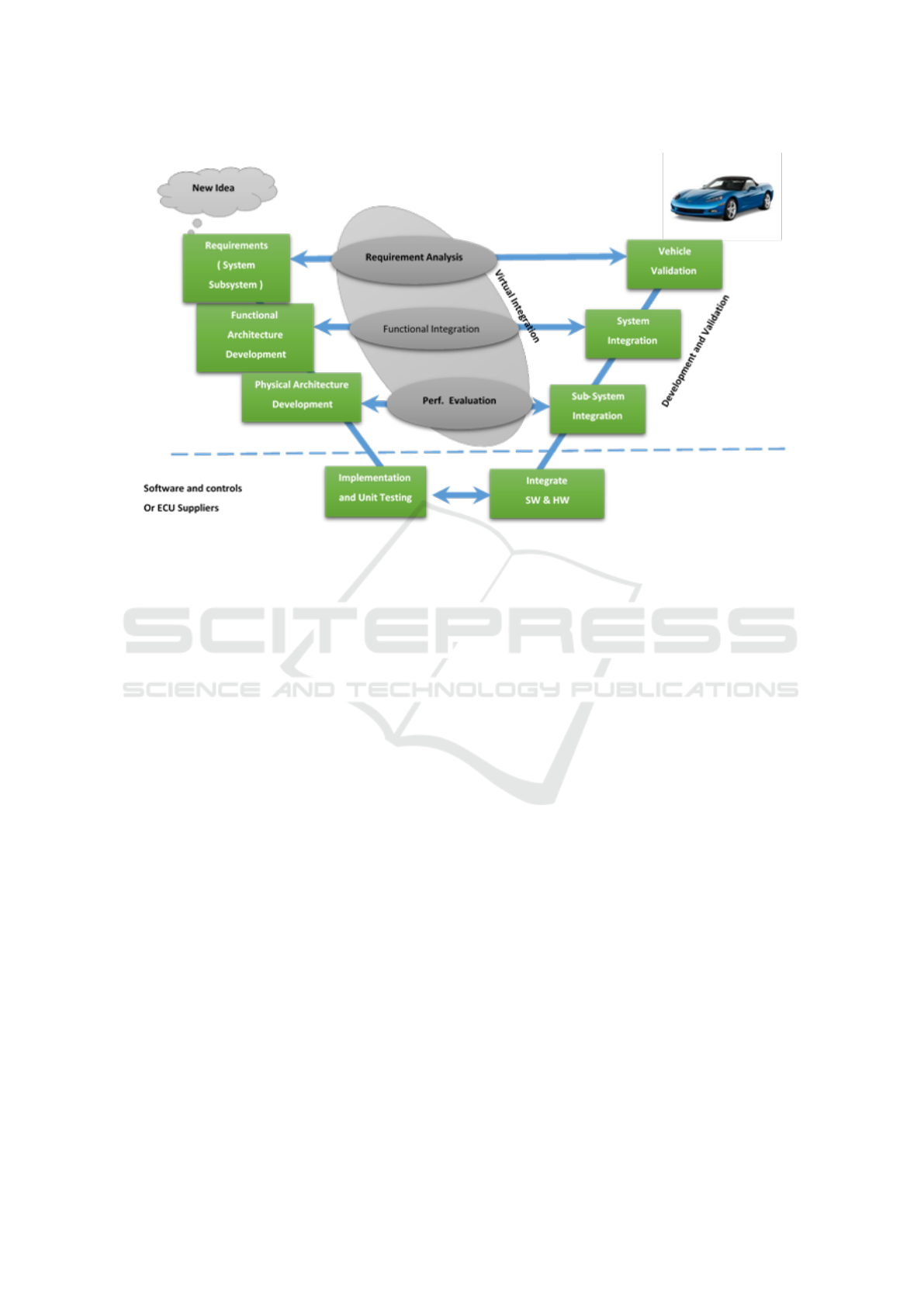
Figure 2: The V-Model of System Development.
and therefore guarantee any hope for (close-to) opti-
mality of the selected design alternative (or set of).
In addition, this approach supports little or no trace-
ability of decisions from requirements to system de-
sign, which is very important to finding root causes
of malfunctioning, and designs not working accord-
ing to the expectations, etc. Moreover, the validation
of the architecture (alternative) is performed via test-
ing on mule-vehicles and hardware benches very late
in the development cycle. Therefore, any assumptions
that were made during the feature development stage
with respect to the performance impact of the hard-
ware/software platform resources of the E/E Archi-
tecture are verified validated very late. Any changes
at this point in the design may be very expensive.
Additional complexities arise, again from considering
product lines and the trade-offs between manufactur-
ing costs (correlated to part numbers) and give-away
costs. The wiring harness optimization is an area that
has seen some progress with the emergence of tools
such as Mentor Graphics Capital.
A new E/E architecture development involves
many steps which address the various business chal-
lenges such as low-cost, weight, time to market, ro-
bustness, reliability, and security. On the other hand,
there are technical challenges to enable the integra-
tion and optimization of new hardware/software tech-
nologies such as AUTOSAR, high bandwidth proto-
cols such as Ethernet, and high processing power on
the controller (multi cores) without suffering from di-
minishing returns. Conventional E/E architecture de-
velopment process is not capable of addressing these
challenges.
Consider the well-known V-model of develop-
ment used in the auto industry, given in Figure 2. The
new methods and tools used for architecture devel-
opment and exploration are on left hand side of the
‘V’ curve. As described earlier, this methodology of
strengthening the design verification early in the de-
sign cycle will increase the robustness of the archi-
tecture and reduce time and cost in the redesign. The
new process relies of virtual integration of models for
functional and performance verification. Functional
verification using models is well-known and we will
focus on performance verification here.
Performance Verification
There are two main approaches to performance veri-
fication which we shall briefly discuss here.
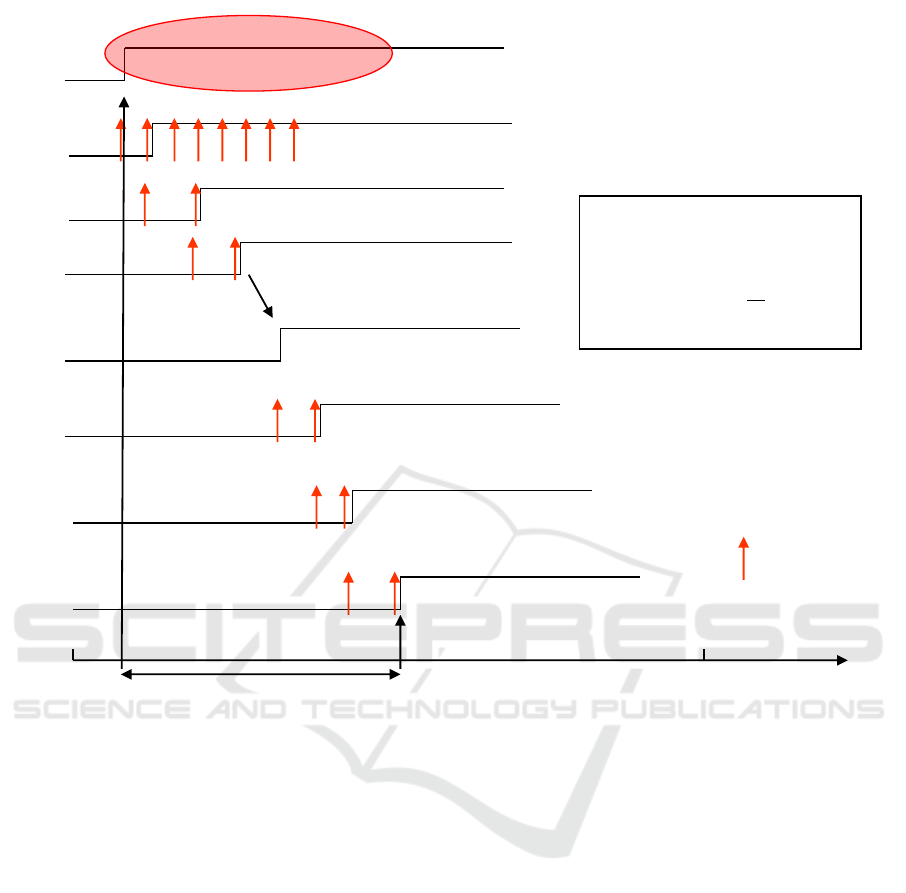
Analytical methods is a well-known approach to
performance verification. They are fast and consist of
identifying the corner cases of a design, like the worst
case or best case scenario and constructing a math-
ematical representation of this case in the form of a
mathematical formula. This formula is then used to
compute the necessary performance metrics. An ex-
ample of analytical methods, illustrated in Figure 3, is
the latency analysis of CAN buses using tindell anal-
ysis (Tindell et al., 1995), used widely in the automo-
tive industry. The graph on the left side of the figure
describes the corner case scenario and the recursive
IndTrackMODELSWARD 2016 - MODELSWARD - Industrial Track
708
Time
(ms)
Sensor A
IO Task B
TxTask
CAN Bus
RxTask
IO Task D
Actuator E
0
Msg C
Legend:
Sample
Instance
End to End Latency, T
AE
Event Driven
Execution!
Value Needs to
Hold !!!
K
khpll
k
l
k
kk
msgC
inTasksInChakk
kkAE
JC
T
r
Cr
RrTT
)(,
,
)(
Assumptions:
All tasks are periodi c and unsynchronized
with each other. CAN messages are sent
synchronously by the CAN controller.
Figure 3: End to End Latency Timing Model for CAN Protocol.
equation shown on the right side is the formula for the
analysis. This equation is solved iteratively to com-
pute the worst case latency of a CAN bus. The models
used in the analytical methods are often abstract and
at the very early stage of the development and helps
in exploring the architecture alternatives efficiently.
An alternative to analytical methods is simulation
based methods. In these methods, the behavior and
the performance of the system are modeled and ex-
ecuted on a virtual platform (as opposed to the real
target vehicle platform). An appropriate set of sce-
narios, representative of the typical use cases of the
systems, are simulated to compute the performance
of the system. A well-known simulation based tool
for the performance evaluation of automotive con-
trol systems is SimEvent toolbox available in Mat-
lab. This toolbox has an associated discrete simu-
lation engine which can be used for simulating the
model over representative input space and calculating
the system performance. Figure 4 illustrates an exam-
ple of a SimEvent model simulating the partial net-
work based power consumption model. In this figure,
the SimEvent model is the network of blcoks shown
on the left hand side and the waveforms shown on
the right hand side are the inputs and outputs to the
model.
The fidelity of simulation methods depends upon
the degree of details included in the models. For in-
stance, one should include the transmission and re-
ceive buffers as they cause a major potential timing
bottleneck, to better assess the performance of the
CAN protocol, The major drawback of simulation
based methods is that simulation scales inversely with
the model complexity; larger the model complexity
and system, higher the simulation times are.
5 CONCLUSION
The design and development of E/E assets is becom-
ing a critical component in the development of mod-
Modeling and Analysis of Automotive Systems: Current Approaches and Future Trends
709
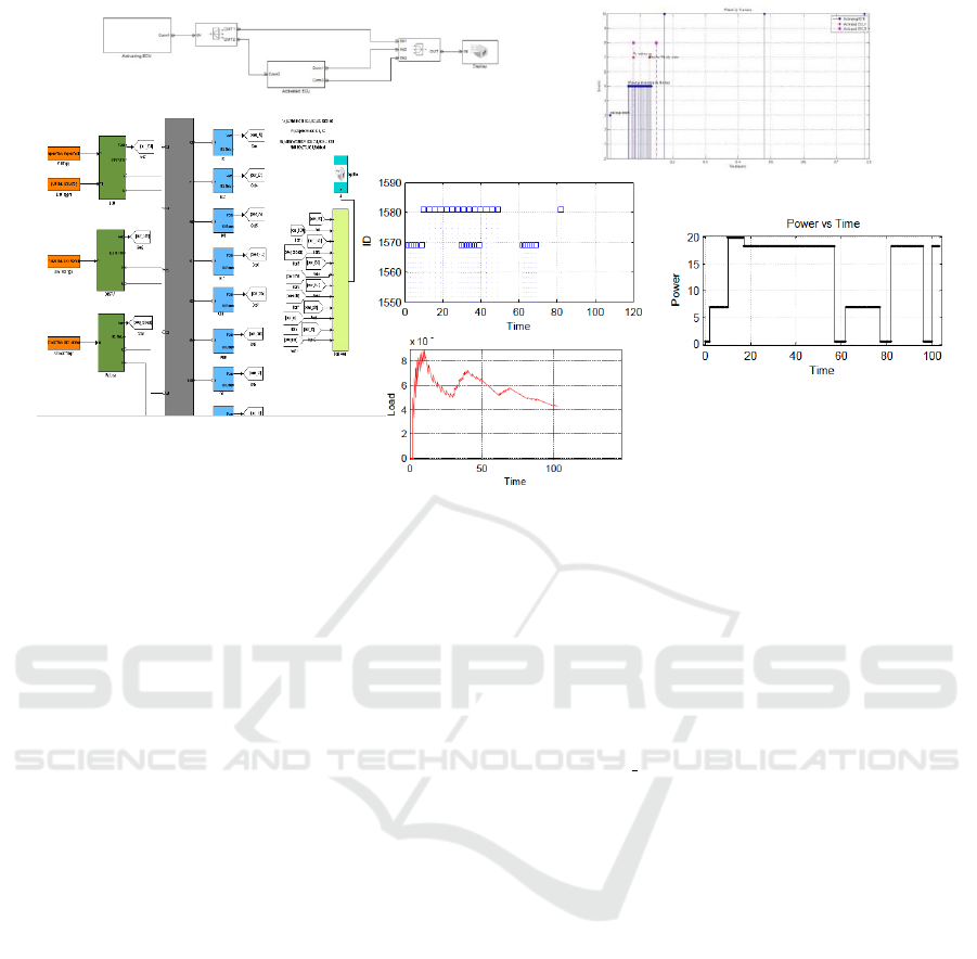
Figure 4: Matlab-SimEvent Simulation Models.
ern day automotive systems. Model-based develop-
ment, product-line engineering and virtual develop-
ment are some of the key-methodologies successully
employed in the industry. Several commercial tools
have been proposed to support these methodologies.
This paper highlights how some of these tools are be-
ing used in GM as well as in other automotive indus-
tries.
ACKNOWLEDGEMENTS
The authors would like to thank Bran Selic for push-
ing us to write this paper, Shoham Ben-David for
her generous support in reading the paper at differ-
ent stages of preparation and providing very useful
comments. We thank also Joseph D’Ambrosio for his
constructive comments.
REFERENCES
AUTOSAR (2003). AUTomotive Open System ARchitec-
ture. www.autosar.org.
BigLever (2012). BigLever’s Gears Product Line En-
gineering Lifecycle Framework. Software Prod-
uct Line Conferences. www.biglever.com/solution/
framework.html.
Clements, P. and Northrop, L. (2001). Software Product
Lines: Practices and Patterns. Addison-Wesley Pro-
fessional, Boston, MA, USA.
Flores, R., Krueger, C. W., and Clements, P. C. (2013).
Second-generation product line engineering: A case
study at general motors. In Systems and Software
Variability Management, Concepts, Tools and Expe-
riences, pages 223–250.
GMPT (2004). General Motors Powertrain: Product Line
Hall of Fame. Software Product Line Conferences.
http://splc.net/fame/gm.html.
ISO26262 (2011). International Standards Or-
ganization (ISO), Road Vehicles – Func-
tional Safety. http://www.iso.org/iso/
catalogue
detail.htm?csnumber=43464.
Tindell, K., Burns, A., and Willings, A. (1995). Calculating
controller area network (can) message response times.
Control Engineering Practice, 3(8).
IndTrackMODELSWARD 2016 - MODELSWARD - Industrial Track
710
