
Comparing System- and Test Model with Integrated Software-based
Signal Simulation
Andreas Kurtz
1
, Bernhard Bauer
2
and Marcel Koeberl
1
1
BMW Group, ’Integration Electric/Electronics, Software’, Knorrstr. 147, 80788 Munich, Germany
2
Software Methodologies for Distributed Systems, University of Augsburg, Universitaetsstr. 14, 86135 Augsburg, Germany
Keywords:
Automotive, AUTOSAR, Distributed Systems, Method, Model Based Testing, Path Detection, Path Reduc-
tion, Simulation, System Model, Test Automation, Test Model, Testing.
Abstract:
Test automation in distributed systems requires new methods in signal simulation for the stimulation of the
distributed system. Increasing complexity of electric electronic (E/E) systems enhances the testing-effort. The
main challenge is reducing the time consuming manual stimulation in consideration of improving the quality of
testing. Currently used systems for test automation with a software-based approach have to be adapted to each
hardware and software version of the system to be tested. The approach represented shows a new approach
through the integration of a simulation service in the AUTOSAR software architecture. By integrating a
generic software-based simulation module with an interaction point at the basic software driver layer, the
execution of tests can be automated and improved under consideration of adaptivity and reproducibility.
1 INTRODUCTION
Mastering complexity and customer orientation are
challenges in the development of electric and elec-
tronic (E/E) functions in the automotive industry. In
current and future vehicles, the increase of the dis-
tribution of functions and the networking demands
new ways of automation for testing customer features.
Software bugs are the main reason for malfunctions in
new developed cars. In the automotive industry, the
safety requirements are outstandingly important be-
cause of its impacts. Therefore, there is a need to err
on the side of caution.
In this paper, we focus on developing a method for
generic signal simulation for testing the system model
at total system platform. System model stands for the
total system deemed to be a distributed system with
its networked hardware (HW) and software compo-
nents (SWC). The long-term goal is an integrated dis-
tributed signal simulation to realize the virtualisation
of the customer input for testing the maximum chain
of reaction of customer features.
1.1 Problem Statement
Increasing complexity of developed functions with
shorter developing time leads to exceeding use of
methods. Figure 1 shows the raising input of using
methods when reducing development time to handle
equal effort. In addition, of an increase of system
complexity the conventional methods have to change
to virtual development methods. Virtualization is a
key factor in testing the total system to be able to han-
dle the increase of complexity.
Figure 1: Reducing time demands increase of using meth-
ods to manage the effort. (Eigner and Stelzer, 2013).
State-of-the-art integrated simulation functions,
used in automotive software development, do set sig-
nal values via additional functions integrated in the
software components to be tested. If we take a closer
look on the kind of implementation, we recognize that
the point of interaction is often housed in the imple-
mentation of the customer- or a part function. These
simulation functions interact with the customer func-
tions and require specific solutions for each type of
implementation.
656
Kurtz, A., Bauer, B. and Koeberl, M.
Comparing System- and Test Model with Integrated Software-based Signal Simulation.
DOI: 10.5220/0005751006560662
In Proceedings of the 4th International Conference on Model-Driven Engineering and Software Development (MODELSWARD 2016), pages 656-662
ISBN: 978-989-758-168-7
Copyright
c
2016 by SCITEPRESS – Science and Technology Publications, Lda. All rights reserved
Using this kind of simulation/testing functions
does not reflect the functional behaviour of the soft-
ware function like in customer usage. Additional sig-
nals and interfaces are used to get access to the imple-
mented customer functions.
Another aspect is the additional software code,
implemented in the SWC itself, which is needed to re-
alize the interaction. Due to high level of interaction,
crosslinked functions are not recognized, so malfunc-
tions in close-by or networked SWCs are not noticed.
Testing by physical simulation of sensor signals
at the hardware interface does represent the customer
usage but is too complex to find specific solutions for
each HW variation. The main challenge for physical
signal simulation is to find a generic solution for all
types of sensors and interfaces.
Getting a picture of the developed method, we are
thinking of a distributed software-based virtualisation
of signals in the distributed system. With the focus
on the automotive domain, the system architecture is
based on AUTOSAR. The generic architecture, of an
electronic control unit (ECU), is shown in Figure 2
(AUTOSAR Partnership, 2014).
Figure 2: AUTOSAR Architecture, Components and Inte-
gration (AUTOSAR Partnership, 2014).
1.2 State-of-the-Art
Established methods in model based testing, as a basis
for automotive software testing, are (Roßner, 2010):
• Component Test
• Integration Test
• System Test
• Acceptance Test
Sensor signal simulation at Component Tests or so
called Unit Tests are quiet simple. For example, with
a simulation of the remaining bus or stimulating phys-
ical hardware signals via e.g., pulse-width modulation
(PWM) generators. If we look at the Integration Test
or System Test, the distribution of functions increases
complexity. In addition simulation of input signals is
getting more and more complicated.
In the following, the Navigation system (Navi)
consisting of two components is used to explain the
developed method of integrated signal virtualisation.
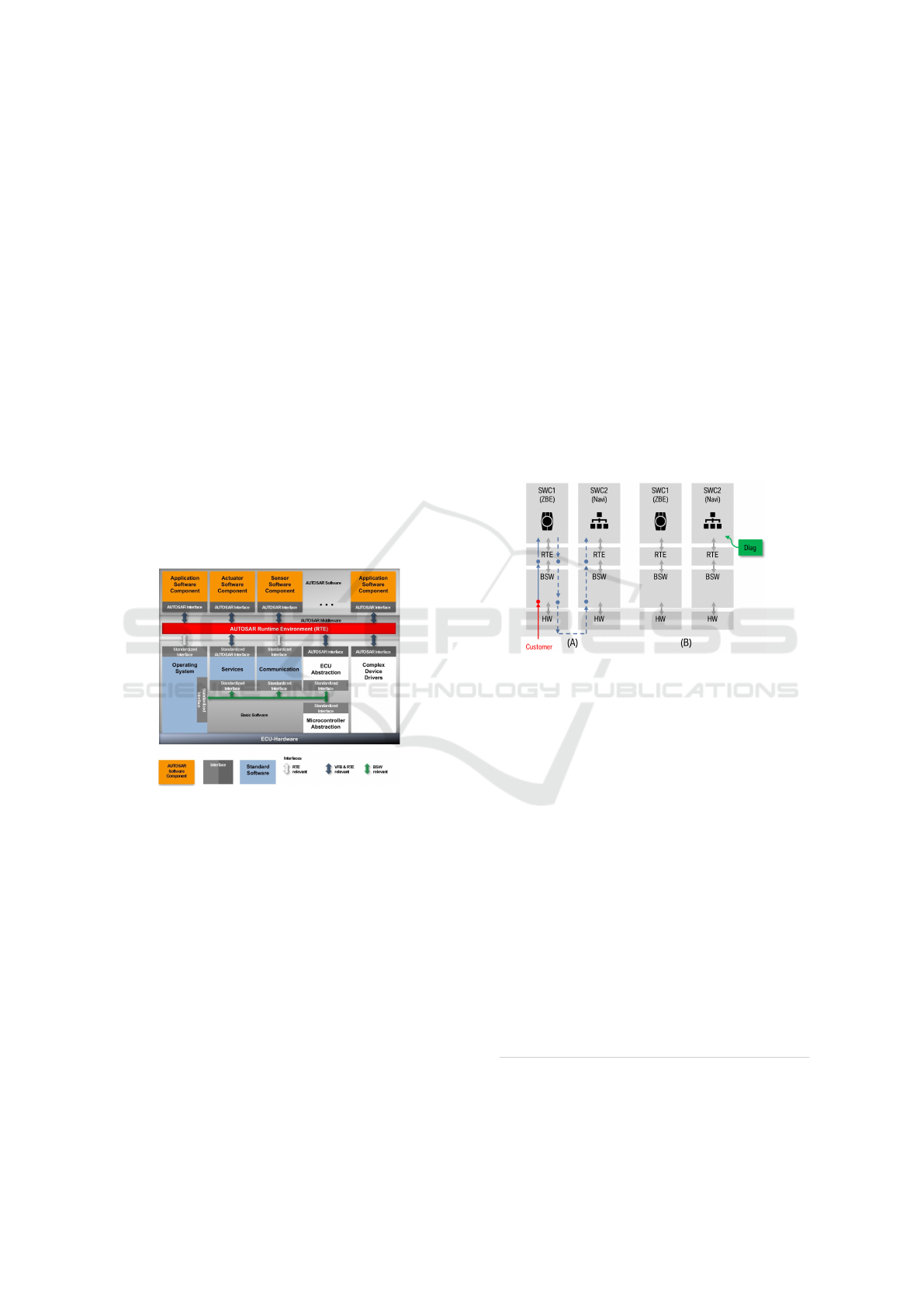
The structure symbol in Figure 3 symbolizes the
structure of the navigation system menu.
Figure 3 shows the same architecture for both
cases and two SWCs representing a distributes sys-
tem. Figure 3 shows a simplified software architec-
ture with the main layers. From bottom up, above
the HW there is the basic software (BSW) allocated.
The BSW contains modules shown in Figure 2 pri-
mary providing an operating system, communication
services, signal- and communication abstraction and
HW-driver. All communication to the Application-
SWCs is distributed via the runtime environment
(RTE).
Figure 3: Software-Architecture - [simplified draft];
(A) Customer, (B) Simulation state-of-the-art.
Conventional software-based simulation methods
interfere at the application SWC layer, shown in Fig-
ure 3(B) named ’Diag’. Usually these functions are
integrated for software-based internal error detection
and setting data trouble codes (DTC).
Figure 3(A) shows a customer interaction and sig-
nal path with the total system via the iDrive con-
troller (ZBE) representing the human machine inter-
face (HMI). The signal path starts at the SWC1 BSW
and is handed to SWC1. SWC1 interprets the cus-
tomer input and sends a message via HW interface to
SWC2.
With reference to the example, we look closer to
the software architecture at a test case specified in
Listing 1. The test case is called ’Start Guidance via
entering Navigation Destination’ and can be operated
by the customer in several ways. This is the reason to
restrict the operation to a specific test case. Following
manual test is synonymous with customer use.
1 Purpose
2 Start G u idan c e via e nter i n g
Ç Navig a t ion Dest i n at i o n
3 Focus : hitt i n g the r i g h t me n u s
Comparing System- and Test Model with Integrated Software-based Signal Simulation
657
4 Testdata
5 CAN message s
6 STATUS _ Z BE = {st _ btn 1 , st _ btn 2 ,
Ç st_ btn 3 , st _ b tn 4 , st _ btn 5,
Ç st_ btn 6 , st _ b tn 7 , btn _ ente r ,
Ç r o t a t e _ s t e p s }
7 STATUS _ P LD ={parking, living,
Ç driving, invalid, empty}
8 apiJob (ECU , " steuer n \_ routine ",
Ç " ARG ; MENU ; RRR " ,
Ç \%i;\%i;\%i;\%i)
9 Precondition
10 bus monit o r ing active , car is in
Ç living mode , l a s t st a tus of
Ç m e s sage ST A TUS _ P LD = living
11 Steps
12 Enter D est i nat i on via ZBE
13 -> Menu - N a v iga t i on - New
Ç D est i nat i on - ’ enter
Ç address ’ - S t a r t Guidanc e
14 Expected test result
15 STATUS _ P LD = living
16 STATUS _ Z BE = st_ btn 3[1 ∣ 100
Ç ms< t
pushed
< 200ms ]
17 ...
18 STATUS _ Z BE = btn _ enter [1 ∣ 100
Ç ms< t
pushed
< 200ms ]
19 apiJob
Ç s t e uern _ rou t i n e { ARG ; M E N U ; RRR }
Ç = [ 19 2 7 ;7 6 87 ; 0; 0 ]
Listing 1: Example test case ’Start Guidance via
entering Navigation Destination’.
The conventional virtual interaction uses func-
tions, called diagnosis job (Listing 2) to hit the right
menu items.
1 apiJob (ECU , " steuer n \_ routine ",
Ç " ARG ; MENU ; STR " ,
Ç \%i;\%i;\%i;\%i)
Listing 2: Example Diagnosis-Job.
This function uses a unique identifier (ID) to hit a
specific menu item. A series of these jobs is necessary
to reach the same goal (in this case an entered navi-
gation destination). Thus the test result for this test
has to be Menu ID = 1927 and selected Menu Item
= 7687. For both cases we see the same appearance
(MENU ITEM) shown in Listing 3, but in case of the
simulation (Listing 3 - Diag.) the CAN messages are
missing.
The test with this kind of customer simulation is
far away from the normal customer use (Listing 3 -
manual). The state-of-the-art simulation method only
tests the internal behaviour of a single software com-
ponent. The result is that errors in the data commu-
nication that occur in the customer case are not de-
tected.
1 Test result manual ( Fig : 3. A )
2 STATUS _ P LD = living
3 STATUS _ Z BE = st_ btn 3[1 , 131 ms ]
4 ...
5 STATUS _ Z BE = st_ btn _ e n t e r [1 , 157 ms ]
6 MENU _ ID = 1927
7 MENU _ ITEM = 7687
8
9 Test result D i a g ( Fig : 3. B )
10 STATUS _ P LD = living
11 STATUS _ Z BE = no CAN Me s s a ge
12 MENU _ ID = 1927
13 MENU _ ITEM = 7687
Listing 3: Result test case ’Manual vs. Diag’.
2 THE APPROACH
The goal is comparing system- and test model with
a new approach via an integrated software-based
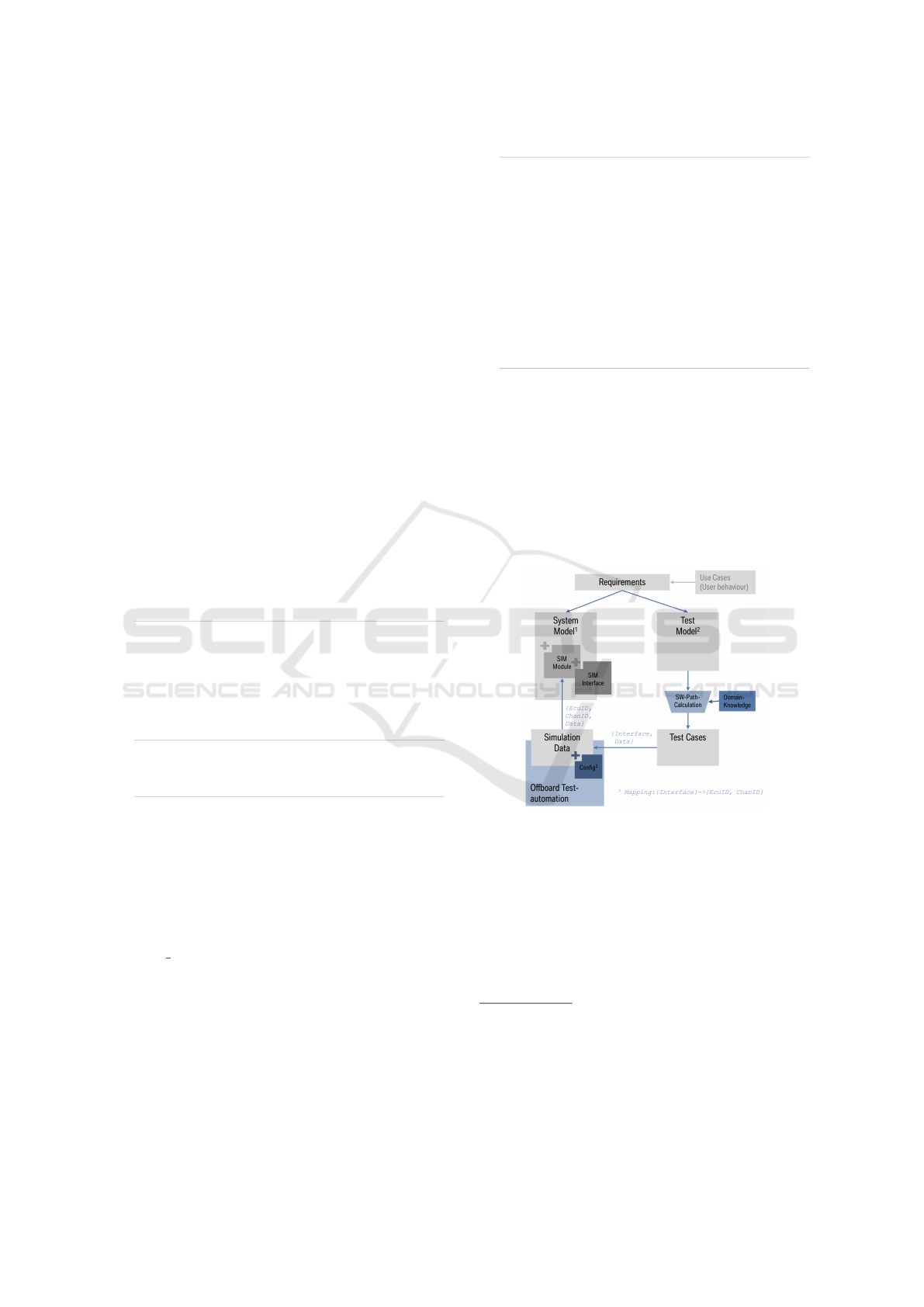
simulation of input signals. Figure 4 shows the
model-based approach of comparing system- and test
model.
123
Figure 4: Approach of comparing system- and test model
based on a standard model based approach.
1,2,3
The methodological approach is to integrate a
generic simulation module (SIM Module) and a sim-
ulation interface (SIM Interface) in the system model
on each component. The novelty of this approach
is the layer of interaction (AUTOSAR driver layer).
The aim of the interaction on this lower software ar-
chitecture level is to reduce data complexity. This is
1
The system model describes the implemented software
solution, including code.
2
The test model describes the specified implementation
for the features and the environment model.
3
Config describes the hardware specific mapping of In-
terface to ECU identifier (EcuID) and channel identifier
(ChanID).
MODELSWARD 2016 - 4th International Conference on Model-Driven Engineering and Software Development
658
achieved through an abstraction of the data in the off
board automation.
– How does this work? – These SIM moduls
can receive test cases from an off board test automa-
tion system and execute the test cases, individually or
jointly, by order of the off board system.
The data for the test cases is computed out of the
test model and transferred in abstract test data and a
mapping table (Config). The separation has the ad-
vantage of using the test case for different hardware
configurations. The separation has the advantage of
using the test case for different hardware configura-
tions.
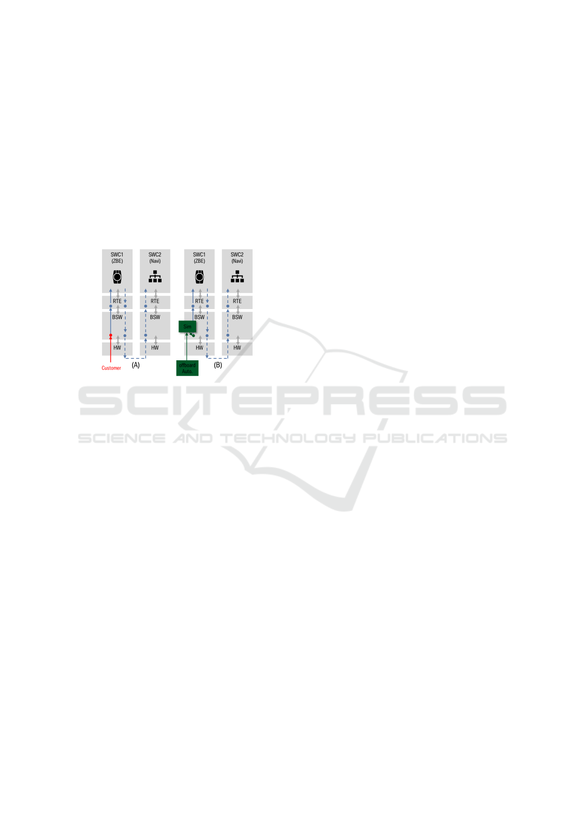
Figure 5: Simulation Approach - SW-Architecture - [sim-
plified draft]; (A) Customer, (B) New simulation approach.
Setting the interaction of the simulation, formerly
manipulation, to the BSW driver interface (Figure
5(B)), especially the SWCs operate closer to the cus-
tomer use. On the one hand, the customer function
cycle is closer to the behaviour in the normal cus-
tomer usage which leads to detection of errors in the
functional implementation or errors between layers.
On the other hand, the simulation gets easier by get-
ting closer to the hardware layer, because of reduced
types of signals. There are only discrete signals, be-
cause all data processing of customer input ends up
in analog digital converter. A positive effect is that
in case of simulation cross-linked functions are trig-
gered as well and show their behaviour as well as the
misbehaviour.
2.1 The Details
The new methodological approach in Figure 4 shows
schematically how the simulation data is loaded to the
SIM module. Based on the assumption that a test
model is available test cases are derived therefrom.
In the derivation of test cases, domain knowledge is
added to obtain relevant test cases. This test case data
is divided into data sequences for each simulation port
and a mapping table. In distributed systems, the use
of domain knowledge is meaningful because the func-
tions set conditions and limitation to each other. E.g
the power-train domain has information about the spe-
cific engine speed range, which is directly linked to
the energy availability in the power-network domain.
This leads to a reduction of possible test cases.
The bigger part of software functions is devel-
oped with a model based approach and realized with
state machines. The main reasons for the increase
of complexity are on the one hand, that conditions
for triggering the transitions are built in various state
machines in different software levels. On the other
hand almost all of the conditions do have timing con-
strains. This expands the number of use cases by
testing boundary values e.g., lower limit, upper limit,
lower limit follower, upper limit follower and last but
not least the time steps on the valid timing interval.
Computing the paths of the state management has
been performed with a data flow based model analysis
(Saad and Bauer, 2013) (Saad and Bauer, 2011). All
paths had to start and end in the main menu with the
requirement that every transition can be passed only
once per path to avoid loops. The result is a set of
paths with the information of states passed, transitions
and trigger for transitions.
The mentioned mapping table (’Config’) is en-
riched with data from the deployment, with the aim
to obtain a architecture-specific mapping table. The
deployment is a part of the software development pro-
cess of AUTOSAR. (AUTOSAR Partnership, 2014)
The configuration (’Config’) is an implementation
specific information computed out of:
• Software Component Description: Describes the
functional dependencies
• System Description: Describes the partitioning of
SWCs to ECUs
• ECU Configuration: Describes the signal routing
to the HW-Abstraction
• Basic Software Description: Describes the map-
ping of the HW-Abstraction to the HW-Channels
These descriptions are provided on generating the
specific AUTOSAR software configuration for the
specified architecture. Therefore the information is
depending on the software of the system model. Er-
rors in the AUTOSAR configuration files are handed
to the simulation. Faults in the hardware port map-
ping in the driver layer will not be noticed, only by
manual testing of correct connection of the sensors to
the ECU (Unit Test).
– The software architecture – Figure 6 shows the
software architecture of the integrated simulation ap-
proach reduced to its modules and ports.
Comparing System- and Test Model with Integrated Software-based Signal Simulation
659
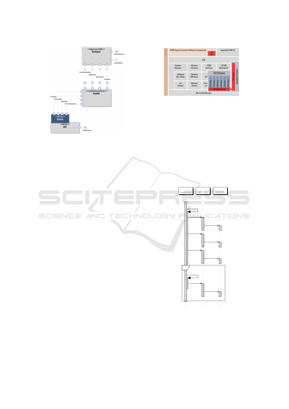
Figure 6: Software Architecture of Simulation module
(K
¨
oberl, 2015).
The new approach is that the SIM module is inte-
grated in each ECU, which reads sensor signals. The
three main components are:
• SimAgent is the logical component, including a
state management and is responsible for the ex-
ecution of the sequences, the internal data storage
and all safety requirements,
• SimGW is a temporary solution to avoid changes
in the hardware abstraction and does only route
the signal data to the MCAL-Layer,
• DioSim is the interface to the existing Dio and its
read services with the goal to replace the physical
signals with the simulated, stored in the SimA-
gent.
The Gateway module is used to route the sig-
nals from the SimAgent to the DioSim. This is a
temporary solution that we do not have to edit the
I/O-Abstraction of the existing AUTOSAR basic soft-
ware. Above the RTE there will be the Sim Agent as
a part of the BMW System Function Software Compo-
nents next to the normal application software compo-
nents (Figure 7). BMW System Functions are stan-
dardized software components that are integrated into
each ECU, e.g., Diagnosis or DTC-Functions.
The allocation of the modules in the AUTOSAR
layered architecture is shown in the Figure 7. Stan-
dard SWCs like system time, standard diagnosis, au-
thentication or mentioned above are clustered in the
BMW System Function Components.
– The simulation process – Enabling of the simu-
lation will follow the process shown in sequence dia-
gram Figure 8.
• Init(), activating the SimAgent via diagnosis job
(CAN-Message),
Figure 7: Integration of Simulation Interface in AUTOSAR
Driver Layer.
• FlushSim(), erasing existing data in the memory,
• UpdateSim(), setting initial values and parame-
ters, like start value and start time,
• EnableSimulation(), activating the simulation ser-
vice.
After enabling the simulation service, the Up-
dateSim-Function is used to feed the DioSim-module
with the data during the simulation. The provision
of the simulation data in the driver layer is non-
interacting with the AUTOSAR read services, in or-
der not to influence the BSW behaviour.
Sim Agent
SimGw DioSim
Init()
FlushSim()
FlushSim()
UpdateSim()
UpdateSim()
EnableSimulation()
EnableSimulation()
Cyclic()
UpdateSim()
UpdateSim()
looploop
Figure 8: Process Start of Simulation Service (K
¨
oberl,
2015).
The novelty here is that a test case, respectively
the signal sequences, is saved locally in the ECU
memory and is executed by the SIM Agent. Each SIM
module has to keep only the information necessary for
the ECU specific signal simulation.
MODELSWARD 2016 - 4th International Conference on Model-Driven Engineering and Software Development
660
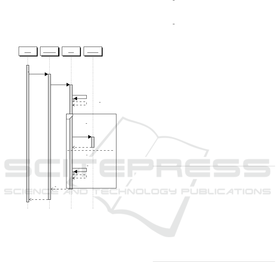
Reading data from the RTE and the chain of reac-
tion through the AUTOSAR basic software is shown
in Figure 9. If there is a request of a RTE variable,
the normal chain of reaction will be triggered. If the
request reaches the Dio-module the Dio-module will
check if there is a simulation active for the requested
channel (GetSimState()) and will switch to the simu-
lated data if required. In all other cases the physical
state of the hardware input port will be read.
RTE IoHwAb
Dio
DioSim
sym runHwIoService()
ReadChannel()
GetSimState()
DioSim
SimulationState
GetSim()
int
Origin ReadChannel()
int
altalt
[DioSim SimulationState ==
ENABLED]
[DioSim SimulationState !=
ENABLED]
Dio LevelType
int
Figure 9: Simulation Service process (K
¨
oberl, 2015).
The additional function request GetSimState() will
be integrated in the Dio-module and will have an in-
significant influence on the time response of the re-
quest. There will be no difference between the time
response in normal customer use or in simulation us-
age, because in both cases the new additional function
request will be triggered.
The worst case execution time analysis (WCET)
calculates an increase of the processor workload
about 3,3%. This is a calculation for 255 simultane-
ously simulated channels, on an 80MHz CPU with a
task cycle of 1ms and in case of an error, that no simu-
lation data is available. In this case the software reads,
after failure of reading a simulated value, the physical
value of the hardware input port.
Based on an 80MHz CPU, we are using for re-
search and analysis, with a 12.5ns Assembler instruc-
tion we calculated execution times for 1ms tasks. The
first one is with no simulation active and the second
one is with simulation active without data, represent-
ing the worst case scenario.
• DioSim GetSimState=0 [normal case]
& no active Simulation
WCET = 12,5ns according to 1 function call
• DioSim GetSimState=1 [worst case]
& no Simulation Data
& Reading real data
WCET = 32950ns
An impact could be a time delay being critical for
a SWC. In normal case the SWC runs in tasks about
10ms and the calculated delay will be about less than
0,01%.
The last part is a SWC controlling the simulation
located on the ECUs to control the simulation process
in consideration of safety and CPU-Performance of
the ECU and the memory workload. This SWC will
be added in further tests to make sure that there will be
enough CPU-Performance left. Stopping mechanisms
and fall-back solutions are already integrated.
The results of comparing the system reaction in
customer usage to the conventional automation ap-
proach deviate. The following results (Listing: 4),
with the integrated new simulation approach, show a
similar system reaction to the customer usage.
1 Test result manual ( Fig : 5. A )
2 STATUS _ P LD = living
3 STATUS _ Z BE = st_ btn 3[1 , 131 ms ]
4 ...
5 STATUS _ Z BE = st_ btn _ e n t e r [1 , 157 ms ]
6 MENU _ ID = 1927
7 MENU _ ITEM = 7687
8
9 Test result SIM ( Fig : 5.B )
10 STATUS _ P LD = living
11 STATUS _ Z BE = st_ btn 3[1 , 131 ms ]
12 ...
13 STATUS _ Z BE = st_ btn _ e n t e r [1 , 157 ms ]
14 MENU _ ID = 1927
15 MENU _ ITEM = 7687
Listing 4: Result test case ’Manual vs. SIM’.
First researches show that the simulation of one
to fourteen digital imput ports does work on a vir-
tual ECU without measurable effects on the CPU-
Performance.
2.2 Related Work
Model based testing is the basic approach in the auto-
motive product development. Methods for data-flow
analysis with the help of domain knowledge can help
to improve the explained method by computing real-
istic software-paths and the corresponding data sets.
Comparing System- and Test Model with Integrated Software-based Signal Simulation
661

With the help of this information, the test model can
be improved to get near 100% test coverage in consid-
eration of the customer use cases. Domain knowledge
is the key for computing user realistic paths. Unre-
alistic paths only have to be checked referring their
impact on customer functions and common bugs.
A similar approach with focus of ’automation,
modularization and compatibility of all equipment to
do measurement, calibration and diagnosis’ (ASAP,
1999) is the Can Calibration Protocol (CCP). The Pro-
tocol is used for calibration and data acquisition. Re-
alized as a driver with access to the internal ECU
memory this part of the protocol has a similar effect
on the CPU load as the introduced approach. During a
session using CCP a ’continuous logical connection’
(ASAP, 1999) is established to transfer data from the
ECU to the master device (off board test automation).
This approach has a substantial similarity in the
connection layer: both interact at the driver layer.
However, according to the illustrated approach the
CCP has the main goal of data acquisition in contrast
to data simulation. With the enormous difference of
cutting the data communication to the agent (slave)
the new approach is, in case of simulation, way nearer
to the customer case.
3 CONCLUSIONS
The method of integrated hardware signal simulation,
with an integrated software approach, allows to sim-
ulate the user input analogous to the customer use
cases and thereby to compare system- and test model
in an innovative way. The approach shows a differ-
ent solution with no need of special hardware equip-
ment because of the integration of the simulation in
the distributed system as a distributed system. Real-
ized as a standard module for easy integration in the
AUTOSAR basic software to get an interface for sim-
ulation. The key aspect is the point of interaction lo-
cated in the AUTOSAR driver layer. The approach
uses an abstraction to simplify the data to generic sig-
nal sequences as well as to be able to adapt easily to
different hardware configurations.
A simple generic simulation module controls the
process of simulation, because of its simplicity the
simulation does not have a measurable effect on the
processor workload. The total system reaction, re-
spectively the system interaction with the environ-
ment and customer will be evaluated with proven and
tested methods, already in use. Therefore, there is no
need in building up new evaluation methods.
Next steps for the simulation approach are to
check the data size of the simulation sequences, es-
pecially for long term simulations, considering of the
limited memory space in automotive ECUs. This fact
is the main limitation for the length of data sequences
at this time.
REFERENCES
ASAP (1999). Can calibration protocol - version 2.1.
AUTOSAR Partnership (2014). Autosar components.
Balzert, H. and Ebert, C. (2008). Lehrbuch der
Sofwaretechnik. Spektrum Akademischer Verlag, Hei-
delberg, 2 edition.
Beizer, B. (1990). Software testing techniques. International
Thomson Computer Press, New York, 2 edition.
Byhlin, S., Ermedahl Jan Gustafsson, A., and Lisper, B. Ap-
plying Static WCET Analysis to Automotive Commu-
nication Software.
Eigner, M. and Stelzer, R. (2013). Product-Lifecycle-
Management. VDI. Springer, Berlin, Heidelberg, 2
edition.
Hoffmann, D. W. (2008). Software-Qualit
¨
at. EXa-
men.press. Springer, Berlin, Heidelberg.
K
¨
oberl, M. (2015). Integration softwarebasierter automa-
tisierungsmethoden in eine test-ecu. Master’s thesis,
University of Augsburg, Augsburg.
Myers, G. J., Sandler, C., and Badgett, T. (2012). The art of
software testing. John Wiley & Sons, Hoboken, N.J,
3 edition.
Pezz
`
e, M. and Young, M. (2008). Software testing and
analysis. Process, principles, and techniques. Wiley,
[Hoboken, N.J.].
Roßner, T. (2010). Basiswissen modellbasierter Test.
dpunkt.verl., Heidelberg, 1 edition.
Saad, C. and Bauer, B. (2011). Industry track of soft-
ware language engineering (itsle), 4th international
conference on software language engineering (sle
2011)(may 2011). The Model Analysis Framework
An IDE for Static Model Analysis.
Saad, C. and Bauer, B. (2013). Model-driven engi-
neering languages and systems. Data-Flow Based
Model Analysis and Its Applications, pages 707–723.
Springer.
Seidl, R., Baumgartner, M., and Bucsics, T. (2011). Prax-
iswissen Testautomatisierung. Basiswissen Testau-
tomatisierung. dPunkt.
Vector Informatik GmbH (2013). Autosar configuration
process - how to handle 1000s of parameters.
MODELSWARD 2016 - 4th International Conference on Model-Driven Engineering and Software Development
662
