
Current and Position Sensor Fault Detection and Isolation for
Driving Motor of In-wheel Independent Drive Electric Vehicle
Young-Joon Kim
1
, Namju Jeon
1
and Hyeongcheol Lee
2, *
1
Department of Electrical Engineering, Hanyang University, Seoul, Rep. of Korea
2
Department of Electrical and Biomedical Engineering, Hanyang University, Seoul, Rep. of Korea
Keywords: Fault Detection and Isolation (FDI), Parity Equation, Fault Diagnosis, Residual, Current Sensor, Position
Sensor, Faulty Sensor.
Abstract: This paper proposes model based current sensor and position sensor fault detection and isolation algorithm
for driving motor of In-wheel independent drive electric vehicle. From low level perspective, fault diagnosis
conducted and analysed to enhance robustness and stability. Composing state equation of interior permanent
magnet synchronous motor (IPMSM), current sensor fault diagnosed with parity equation and position
sensor fault diagnosed with sliding mode observer. Validation and usefulness of algorithm confirmed based
on IPMSM fault occurrence simulation data.
1 INTRODUCTION
Driving motor for Electric car need to satisfy various
requirements such as structural robustness, high
output and torque, wide velocity, vibration, heat-
proof, high efficiency driving control. IPMSM
satisfy above requirements.
IPMSM is widely used in industries in behalf of
induction motor because of higher output and
efficiency than induction motor. Since IPMSM does
not need field coil so rotor rotate same speed with
stator magnetic field. There is no copper loss in
IPMSM design, so IPMSM provide high peak
efficiency compare to induction motor. Also power
to weight ratio is higher that induction motor. With
development of electricity and electronics, it is
possible to apply IPMSM in high performance drive
area.
Vector control is a way to control IPMSM
precisely. Field oriented principle is used to control
magnetic flux, space vector of current and voltage.
Coordinate system that can separate vector to
magnetic flux and torque occurrence is composed.
To control magnetic flux and torque separately, need
to dissociate stator current’s magnetic field and
torque occurrence part and compose a rotary
coordinate system connected with rotor magnetic
field. This is d-q coordinate system.
_____________________________
* corresponding author
To conduct vector oriented control, have to
follow following procedure Measure of phase
voltage and current, change measured data to 2-
phase system (α,β) with Clarke transformation,
calculation of vector amplitude and position angle,
change stator current to d, q-coordinate with Park
transformation, stator current torque and magnetic
field is controlled, output stator voltage space vector
is calculated using decoupling block, changing stator
voltage space vector from d, q coordinate to 2-phase
coordinate related with stator with iPark
transformation, generation of 3-phase voltage with
sine wave modulation.
Since driving motor of in-wheel independent
drive electric vehicle is in wheel, many surroundings
such as physical shock, temperature and humidity
change can cause fault. For stability of vehicle, it
need to diagnosis fault fast and effective and.
There are two ways of fault diagnosis method.
One is Hardware redundancy and another is analytic
redundancy. Hardware redundancy is using same
sensor or actuator that can replace fault part. It is
easy to deal with fault but it need to pay more
expense and assign space. Generally in vehicle,
analytic redundancy is used considering system
information and dynamics characteristic. This paper
is using analytic redundancy to diagnosis fault.
In this paper, suppose that there are fault in
measurement of current sensor and positon sensor.
To isolation and diagnosis the fault, modelling of the
Kim, Y-J., Jeon, N. and Lee, H.
Current and Position Sensor Fault Detection and Isolation for Driving Motor of In-wheel Independent Drive Electric Vehicle.
DOI: 10.5220/0005734902250229
In Proceedings of the 5th International Confererence on Sensor Networks (SENSORNETS 2016), pages 225-229
ISBN: 978-989-758-169-4
Copyright
c
2016 by SCITEPRESS – Science and Technology Publications, Lda. All rights reserved
225
IPMSM is introduced, model based fault detection
and isolation (FDI) is proposed, types of current and
position sensor faults are introduced. Finally,
simulation results for validation of proposed FDI
algorithm.
2 FAULT DIAGNOSIS
2.1 IPMSM Model
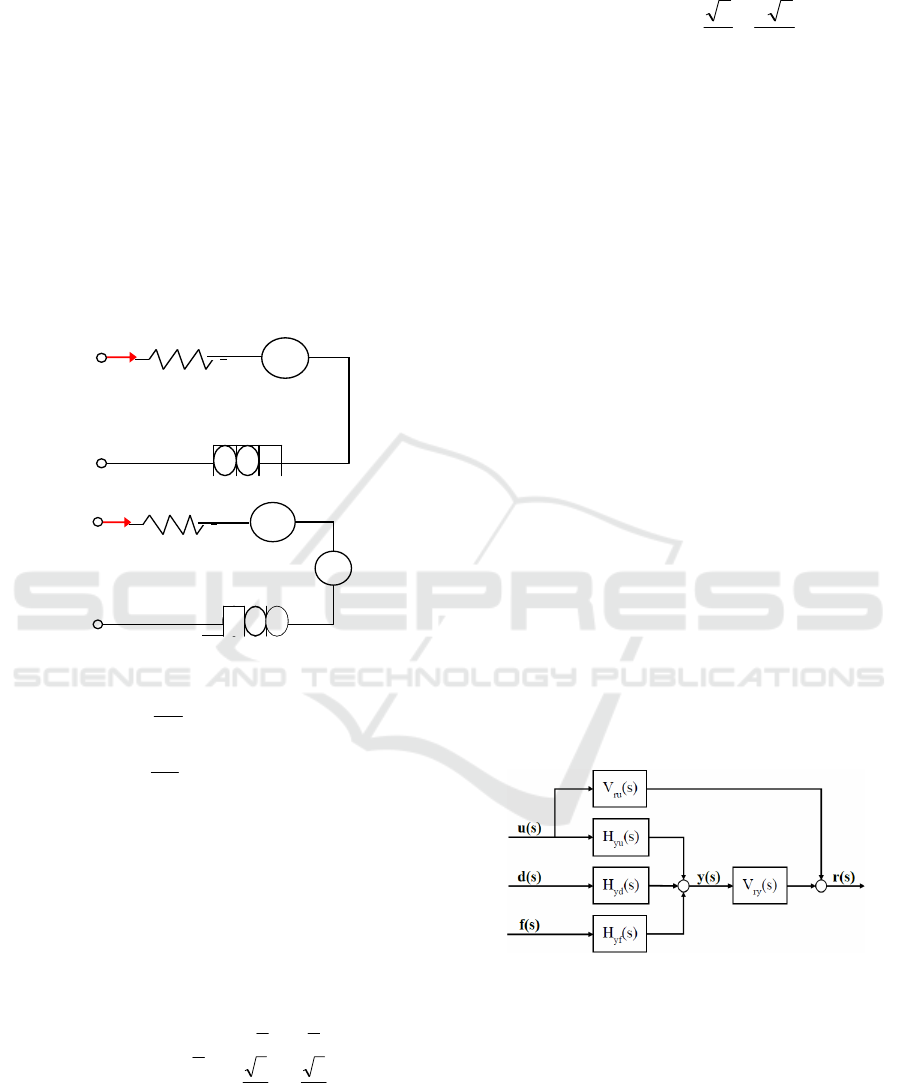
Fig. 1 express d-q equivalent circuit of IPMSM and
Equation1 express voltage equation of d-q rotary
coordinate system.
Figure 1: D-q equivalent circuit for IPMSM.
(1)
,
are the d-q axes applied voltages.
,
are the d-q axes currents,
is the rotor
speed,
R is the armature winding resistance,
,
are the d-q axes inductances,
is the magnet flux
linkage.
Equation (2) is transformation from 3-pahse
fixed coordinate system to 2-pahse rotary coordinate
system.
(2)
Most cases in 3-phase motor system use 2-phase
current sensor does not use 3-phase current sensor
because it costs more. Using motor current
equivalent
+
+
=0, we can eliminate
in
equation (2).
(3)
2.2 Current & Position Sensor Fault
Diagnosis
It is possible to fault diagnosis of current and
position sensor of IPMSM using parity equations.
2.2.1 Current Sensor Fault Diagnosis
To compose parity equation, state space equation is
following.
fduxy
duxx
yy
x
FEDC
EBA
+++=
++=
&
(4)
Where x∈
: state vector, u∈
: the vector of
measured input signals, y∈
: the vector of
measured plant output signals, d∈
, f∈
:
the vectors of unknown input signals, f : the faults
one wishes to detect,
d
: unknown disturbances.
We express equation (4) as transfer function,
following is expressed.
() ()() ()()
0xsHsusHsy
yxyu
+=
(5)
()() () ()
sfsHsdsH
yfyd
++
() ( )
() ( )
() ( )
() ( )
⎪
⎪
⎩
⎪
⎪
⎨
⎧
+−=
+−=
−=
+−=
−
−
−
−
FFAsICsH
EEAsICsH
AsICsH
D BAsICsH
yxyf
yxyd
yx
yu
1
1
1
1
Figure 2: Structure of residual generator using parity
equation.
By using Fig.2’s residual, equation (6) follows.
() ()() ()()
()() ()
()() ()()
()() () ()
() () () () ()
[]
()
()
() ()() () () ()
sfsHsVxsHsV
sd
su
sHsVsHsVsV
sfsHxsH
sdsHsusH
sVsusV
sysVsusVsr
yfryyxry
ydryyuryru
yfyx
ydyu
ryru
ryru
++
⎥
⎦
⎤
⎢
⎣
⎡
+=
⎪
⎭
⎪
⎬
⎫
⎪
⎩
⎪
⎨
⎧
++
+
+=
+=
0
0
(6)
R
d
L
d
i
d
v
qqrp
iLωn
-
+
+
-
-
+
R
q
L
q
i
q
v
ddrp
iLωn
m
φ
ω
rp
n
-
+
+
-
mrpddrp
q
qqq
qqrp
d
ddd
wniLwn
d
t
di
LRiv
iLwn
dt
di
LRiv
φ
+++=
−+=
⎥
⎥
⎥
⎦
⎤
⎢
⎢
⎢
⎣
⎡
⎥
⎥
⎥
⎥
⎦
⎤
⎢
⎢
⎢
⎢
⎣
⎡
−
−−
⎥
⎦
⎤
⎢
⎣
⎡
−
=
⎥
⎦
⎤
⎢
⎣
⎡
c
b
a
q
d
i
i
i
i
i
2
3
2
3
0
2
1
2
1
1
3
2
sincos
cossin
θθ
θθ
⎥
⎦
⎤
⎢
⎣
⎡
⎥
⎥
⎦
⎤
⎢
⎢
⎣
⎡
⎥
⎦
⎤
⎢
⎣
⎡
−
=
⎥
⎦
⎤
⎢
⎣
⎡
b
a
q
d
i
i
i
i
3
32
3
3
01
sincos
cossin
θθ
θθ
SENSORNETS 2016 - 5th International Conference on Sensor Networks
226

To affect by only fault signals, us and ds ’s
coefficients must be 0. So we need to find
and
that satisfy.
[]
0
0
=
⎥
⎦
⎤
⎢
⎣
⎡
I
HH
VV
ydyu
rury
(7)
In this way, state space equating expressed as
follows.
⎥
⎥
⎦
⎤
⎢
⎢
⎣
⎡
⎥
⎦
⎤
⎢
⎣
⎡
−
=
=
⎥
⎥
⎦
⎤
⎢
⎢
⎣
⎡
⎥
⎦
⎤
⎢
⎣
⎡
−
=
⎥
⎥
⎥
⎥
⎦
⎤
⎢
⎢
⎢
⎢
⎣
⎡
=
⎥
⎥
⎥
⎥
⎦
⎤
⎢
⎢
⎢
⎢
⎣
⎡
−−
−
=
⎥
⎦
⎤
⎢
⎣
⎡
=
⎥
⎦
⎤
⎢
⎣
⎡
=
⎥
⎦
⎤
⎢
⎣
⎡
−
=
⎥
⎦
⎤
⎢
⎣
⎡
=
+++=
++=
3
32
3
3
01
sincos
cossin
F
0,
3
32
3
3
01
sincos
cossin
C
1
0
0
1
B,A
,,,
FEDC
EBA
y
_
_
yy
x
θθ
θθ
θθ
θθ
ω
ω
φω
D
L
L
L
R
L
Ln
L
Ln
L
R
i
i
f
i
i
y
nv
v
u
i
i
x
fduxy
duxx
q
d
qq
drp
d
qrp
d
fb
fa
b
a
mrpq
d
q
d
&
(8)
We considered only sensor faults (
=0) and
disturbance is neglectful (
=
=0).
Let
is pseudo constant
5)
and change equation
(8) to transfer function like equation (5)
0
1
3
32
3
3
01
sincos
cossin
=
⎥
⎦
⎤
⎢
⎣
⎡
+−
+
⎥
⎥
⎦
⎤
⎢
⎢
⎣
⎡
⎥
⎦
⎤
⎢
⎣
⎡
−
=
(s)H
sLRLωn
LωnsLR
K
θθ
θθ
(s)H
yd
qdrp
qrpq
yu
(9)
Where K=
R+s
+
+
Applying Equation (9) to Equation (7), can
calculate
and
.
⎥
⎦
⎤
⎢
⎣
⎡
=
⎥
⎦
⎤
⎢
⎣
⎡
−−
−−−
=
01
10
(s)V
LωnsLR
sLRLωn
(s)V
ru
qrpd
qdrp
ry
(10)
So residual is following,
(11)
Now, we make a coordinate transformation to
separate current sensor faults in a, b phase.
(12)
From equation 12, residual
and
affected by
_
and
_
independently.
2.2.2 Position Sensor Fault Diagnosis
Above fault diagnosis algorithm consider only
current sensor fault. To confirm separation
possibility of fault isolation, we need to analysis
correlation with each sensor.
From equation (13) and (14), we can express
sensor information that affect
and
following.
:0=
,
,
,
(13)
:0=
,
,
,
(14)
We can express
and
as fault table.
Table 1: Fault table of fault diagnosis residual.
θ
X X X X
X X X X
X in Table 1 means relation with residual
i =
1,2 and fault of each sensor. If we assume single
fault of system, it is possible that fault is separable
of current sensor
,
and position sensor θ through
and
.
3 SIMULATION RESULTS
Suggested algorithm realized with Matlab/Simulink.
IPMSM control system was selected as AC6 - 100
kW Interior Permanent Magnet Synchronous Motor
Drive in example of Matlab/Simulink. Parameter of
motor model is following in Table 2.
Table 2: IPMSM model parameter.
Parameter Name Value (Unit)
Stator resistance (
R
) 8.296 (mΩ)
d-axis stator inductance (
) 0.174 (mH)
q-axis stator inductance(
)
0.293 (mH)
Magnet flux linkage(∅
71.115 (mV ∙ s)
Inertia(
0.089 (kg ∙
)
Viscous damping( 0.005 (Nm ∙ s)
Pole pairs(
4
() ()() ()()
() ()
)(
3
32
3
3
01
sincos
cossin
su
01
10
sy
susVsysVsr
rury
sf
LnsLR
sLRLn
LnsLR
sLRLn
qrpd
qdrp
qrpd
qdrp
⎥
⎥
⎦
⎤
⎢
⎢
⎣
⎡
⎥
⎦
⎤
⎢
⎣
⎡
−
⎥
⎦
⎤
⎢
⎣
⎡
−−
−−−
=
⎥
⎦
⎤
⎢
⎣
⎡
+
⎥
⎦
⎤
⎢
⎣
⎡
−−
−−−
=
+=
θθ
θθ
ω
ω
ω
ω
() ()
⎥
⎦
⎤
⎢
⎣
⎡
=
⎥
⎦
⎤
⎢
⎣
⎡
=
⎟
⎟
⎟
⎠
⎞
⎜
⎜
⎜
⎝
⎛
⎥
⎥
⎦
⎤
⎢
⎢
⎣
⎡
⎥
⎦
⎤
⎢
⎣
⎡
−
⎥
⎦
⎤
⎢
⎣
⎡
−−
−−−
=
−
2
1
1
)(
10
01
sr
3
32
3
3
01
sincos
cossin
sr'
r
r
sf
LnsLR
sLRLn
qrpd
qdrp
θθ
θθ
ω
ω
Current and Position Sensor Fault Detection and Isolation for Driving Motor of In-wheel Independent Drive Electric Vehicle
227
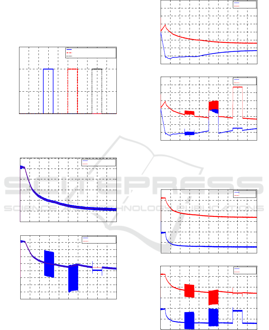
Figure 3 is fault command to each sensor. From
0.5s to 0.7s fault signal to current sensor of phase a
adding 100A offset, from 1s to 1.2s fault signal to
current sensor of phase b multiplying gain 2 and
from 1.5s to 1.7s fault signal to position sensor
adding 0.1 rad offset.
Figure 3: Torque control simulation results (Fault flag).
Figure 4 shows electromagnetic torque of
IPMSM control system respect to reference torque.
(a) Output torque (Normal)
(b) Output torque (faulty)
Figure 4: Torque control simulation results (Output
Torque).
Figure 5 shows d-q axis input voltage of IPMSM
control system.
(a) Rotor voltages (Normal)
(b) Rotor voltages (faulty)
Figure 5: Torque control simulation results (Input voltage).
Figure 6 shows d-q axis current of IPMSM
control system.
(a) Rotor currents (Normal)
(b) Rotor currents (faulty)
Figure 6: Torque control simulation results (Rotor
currents).
0 0.2 0.4 0.6 0.8 1 1.2 1.4 1.6 1.8 2
0
0.5
1
1.5
Time (sec)
Fault Flag
a-axis Current sensor 100A offset fault
b-axis Current sensor double gain fault
Position sensor 0.1rad offset fault
0 0.2 0.4 0.6 0.8 1 1.2 1.4 1.6 1.8 2
0
50
100
150
200
250
300
Time (sec)
Torque (Nm)
Electromagnetic Torque
Reference Torque
0 0.2 0.4 0.6 0.8 1 1.2 1.4 1.6 1.8 2
-150
-100
-50
0
50
100
150
200
250
300
Time (sec)
Torque (Nm)
Electromagne tic Torque
Reference Torque
0 0.2 0.4 0.6 0.8 1 1.2 1.4 1.6 1.8 2
-200
-150
-100
-50
0
50
100
150
200
Time (sec)
Voltage (V)
d-axis Voltage
q-axis Voltage
0 0.2 0.4 0.6 0.8 1 1.2 1.4 1.6 1.8 2
-200
-150
-100
-50
0
50
100
150
200
Time (sec)
Voltage (V)
d-axis Voltage
q-axis Voltage
0 0.2 0.4 0.6 0.8 1 1.2 1.4 1.6 1.8 2
-600
-400
-200
0
200
400
600
Time (sec)
Current (A)
d-axis Current
q-axis Current
0 0.2 0.4 0.6 0.8 1 1.2 1.4 1.6 1.8 2
-600
-400
-200
0
200
400
600
Time (sec)
Current (A)
d-axis Current
q-axis Current
SENSORNETS 2016 - 5th International Conference on Sensor Networks
228
From simulation results, when current and
positon sensor break down, it affects
electromagnetic torque, input voltage and current. It
can be identified that fault of one part can affect
different parts in control system.
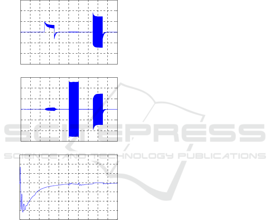
Figure 7 shows proposed algorithm
,
and
in fault situation.
(a) Residuals (
)
(b) Residuals (
)
(C) Residuals (
)
Figure 7: Torque control simulation results (Input voltage).
In Figure 7, like Table 1’s fault table, when
current sensor of phase a breakdown
breaks away
from 0 a lot and when positon sensor break down
both
and
breaks away from 0 a lot. In case of
,
since position estimation’s response is slow so that
insensitive to fault, it does not react that much to the
fault. However assume only single fault, it can be
fault diagnosis and isolation through residual
and
.
4 CONCLUSIONS
In this paper, current and position sensor fault
detection and isolation algorithm suggested and we
confirmed validation with simulation results. This
fault diagnosis method can be applied to In-wheel
independent drive electric vehicle but also it is
possible to apply and extend to other subsystems.
We expect that proposed fault diagnosis algorithm
can develop robustness and stability of electric
vehicle system.
In further study, we will conduct experiment this
system with motor test bench. We hope that we can
obtain same result with proposed fault diagnosis and
isolation algorithm with parity equations.
ACKNOWLEDGEMENTS
This work was supported by the Technology
Innovation Program (Industrial Strategic technology
development program, 10047586, The source
technology development of clean diesel-hybrid
system for 1-liter car) funded By the Ministry of
Trade, industry & Energy (MI, Korea).
REFERENCES
W. L. Soong and N. Ertugrul, 2002. "Field-weakening
performance of interior permanent-magnet motors,"
Industry Applications, IEEE Transactions on, vol. 38,
pp. 1251-1258, 2002.
N. Bianchi and S. Bolognani, 2002. "Interior PM
synchronous motor for high performance
applications," in Power Conversion Conference, 2002.
PCC-Osaka 2002. Proceedings of the, pp. 148-153.
B.-H. Lee, N.-J. Jeon and H.-C. Lee, 2011. "Current
sensor fault detection and isolation of the driving
motor for an in-wheel motor drive vehicle
international conference on control, automation and
systems (ICCAS 2011)," in Control, Automation and
Systems (ICCAS), 2011 11th International Conference
on, pp. 486-491..
M. Blanke and J. Schröder, 2006, Diagnosis and fault-
tolerant control vol. 2: Springer.
Y.-S. Jung and M.-G. Kim, "Sliding mode observer for
sensorless control of IPMSM drives," Journal of
Power Electronics, vol. 9, pp. 117-123, 2009.
0 0.2 0.4 0.6 0.8 1 1.2 1.4 1.6 1.8 2
-300
-200
-100
0
100
200
300
Time (sec)
Residual
0 0.2 0.4 0.6 0.8 1 1.2 1.4 1.6 1.8 2
-300
-200
-100
0
100
200
300
Time (sec)
Residual
0 0.2 0.4 0.6 0.8 1 1.2 1.4 1.6 1.8 2
-0.4
-0.3
-0.2
-0.1
0
0.1
0.2
0.3
Time (sec)
Residual
Current and Position Sensor Fault Detection and Isolation for Driving Motor of In-wheel Independent Drive Electric Vehicle
229
