
Solar Energy Harvesting Solution for the Wireless Sensor Platform
the UWASA Node
Thomas Höglund
1
, Reino Virrankoski
2
and Timo Mantere
2
1
Department of Electrical Engineering and Automation, University of Vaasa, FI-65101, Vaasa, Finland
2
Department of Computer Science, Communications and Systems Engineering Group, University of Vaasa,
P.O. Box 700, FI-65101, Vaasa, Finland
Keywords: Energy Harvesting, Energy Management, Energy Storage, Solar Power Generation, Wireless Sensor
Networks.
Abstract: This paper presents a solar energy harvester and energy management prototype developed for the UWASA
Node wireless sensor platform. The prototype was designed using a modular approach, requiring only minor
hardware modifications in order to allow harvesting from different energy sources. The primary sensor
network application for which the design was developed is wind turbine monitoring. The energy harvesting
prototype and the performance level it enables for the sensor networking are evaluated through experiments,
and methods of optimizing energy harvesting and energy management are discussed.
1 INTRODUCTION
Wireless sensor networks enable a range of
completely new kinds of monitoring and control
applications as a part of the Internet of Things
concept. Even though wireless sensor nodes have
been developed rapidly during the last decade, their
power supply still constitutes a significant
bottleneck for their applicability. Having to service a
wireless sensor node and change its battery can be
prohibitively expensive or difficult due to the
location and means of installation of the sensor
node. This greatly limits the number of feasible
applications in which wireless sensor nodes would
otherwise be perfectly suited for monitoring and
control. Different types of energy harvesting systems
have been developed to overcome this problem. A
common challenge related to them is that the energy
resources they are able to harvest usually enable a
remarkably lower sensor node performance level
compared with powering from a battery without
energy harvesting. This level might not be enough to
fill the requirements of the particular monitoring or
control application.
In this paper we present a solar energy harvesting
solution for the UWASA Node wireless sensor
platform (Yigitler et al., 2010). It was developed as a
part of our wireless automation research activities,
and it is primarily targeted for wireless sensor
network (WSN) applications for wind turbine
monitoring (Höglund, 2014a; 2014b). It would be
beneficial to collect information about different
kinds of forces and vibrations that affect the wind
turbine structures. The dimensions of the wind
turbines used for industrial-scale electricity
generation are so large that energy harvesting
capability is a necessity to make wireless sensor
nodes feasible for monitoring and control
installations. In addition to solar energy, energy
harvesting from vibrations was also considered, and
with small modifications, the developed energy
harvester could be adapted to harvest vibrational
energy.
The rest of this paper is organized as follows:
The UWASA Node wireless sensor platform is
introduced in Section 2. Methods of energy
harvesting are discussed briefly in Section 3 and
general requirements of the energy harvester in
Section 4. The developed energy harvester prototype
is described in Section 5 and the applied solar cell in
Section 6. Maximum power point tracking is
discussed in Section 7. The implemented energy
management and storage is explained in Section 8,
and the system performance is evaluated trough
experiments presented in Section 9. Finally, Section
10 concludes the paper.
50
Höglund, T., Virrankoski, R. and Mantere, T.
Solar Energy Harvesting Solution for the Wireless Sensor Platform the UWASA Node.
DOI: 10.5220/0005734800500057
In Proceedings of the 5th International Confererence on Sensor Networks (SENSORNETS 2016), pages 50-57
ISBN: 978-989-758-169-4
Copyright
c
2016 by SCITEPRESS – Science and Technology Publications, Lda. All rights reserved

2 THE UWASA NODE
The UWASA Node, shown in Figure 1, is an open
source wireless sensor node developed by Aalto
University and the University of Vaasa (Yigitler et
al., 2010). It is a modular and stackable platform, the
software and hardware design of which allow it to be
used for different types of applications with minimal
changes to the main architecture. The possibility to
stack different slave boards onto the main board
allows the creation of custom solutions for any
application. In its simplest form, called the basic
stack, only the main module and the power module
are used. These are sufficient to comprise a wireless
sensor node that consists of processors, a wireless
communication interface, peripheral interfaces, and
power management and distribution (Çuhac, 2012;
Virrankoski, 2012).
Figure 1: The UWASA Node with power module.
2.1 The Main Module
The main module of the UWASA Node contains
two processors: one main controller and one radio
frequency controller. The radio frequency controller
can handle all computation and communication in
simple applications, and then the main controller
need not be used. For more demanding applications,
the main controller is preferable. The main
controller is an LPC2378 ARM7TDMI-S-based
high-performance 32-bit RISC microcontroller from
NXP Semiconductors.
2.2 Operating System and Software
The modularity of the UWASA Node is realized by
both the hardware and the software architectures.
The FreeRTOS (Free Real Time Operating System)
was chosen for the UWASA Node in order to enable
real-time operation and preemptive multitasking.
The UWASA Node can thus handle many
communication, measurement and control tasks
simultaneously.
Middleware has been written for the UWASA
Node to provide device drivers and hardware
abstractions that are used to establish a uniform
programming interface for both the main controller
and the radio frequency controller. The same API
functions can thus be used for programming both
controllers. Automated daemons run in the
background, taking care of tasks related to power
management, time synchronization and system
diagnostics (Çuhac, 2012).
2.3 Auxiliary Hardware
The UWASA Node can be connected to a number of
slave modules by using the hardware stack
connectors with a total of 160 pins per module.
These connectors provide all necessary inter-
modular connections for signals and power supplies.
The slave modules can be any peripherals such as
sensors, actuators and drivers.
2.4 Power Source and Energy
Management
The energy management of the UWASA Node is
handled by the power module, which is a separate
module that can be stacked onto the main module.
The power module features dynamic power path
management and is capable of choosing the most
suitable power source and charging a battery if one
is connected and sufficient power is supplied. There
is a battery monitoring chip that accurately measures
current, voltage and temperature. This can be used
for calculating the energy state of the battery and for
measuring the power consumption of different
applications (Çuhac, 2012).
The battery input of the power module is
designed for one-cell lithium ion batteries with a
nominal voltage of 3.7 V. It accepts voltages
between 1.8–4.2 V. A charger input features an
undervoltage lock-out (UVLO) that cuts the power
when the charger voltage is below 3.3 V. During
undervoltage lock-out a very small, but nontrivial
current (tens of milliamperes were measured) is
drawn from the charger input. Similarly, a very
small but nontrivial current flows into the battery
input when the battery voltage is below 1.8 V and
the charger is in short circuit mode. To eliminate this
loss, an external, very low-power UVLO circuit is
proposed for energy harvesting applications.
Solar Energy Harvesting Solution for the Wireless Sensor Platform the UWASA Node
51

3 METHODS OF ENERGY
HARVESTING
For outdoor WSN applications, such as wind turbine
monitoring, solar energy harvesting is the most
suitable energy harvesting method because of the
good availability of sunlight and the proven
technology of solar cells. Energy harvesters using
sunlight as their energy source can provide power on
the order of 10 mW/cm
2
under ideal circumstances
(Höglund, 2014a).
The most efficient method of energy harvesting
is always case-specific because of the large
differences in the availability of energy over time
from different sources and locations, and because of
the highly varying power consumption of wireless
sensor nodes (Höglund, 2014a). There are three
methods of energy harvesting that were deemed
feasible for supplying the UWASA Node with
power in wind turbine monitoring applications: solar
energy harvesting using photovoltaic (PV) cells,
vibration energy harvesting using a piezoelectric
cantilever, and wind energy harvesting using a
microscale wind turbine with an electromagnetic
generator. These three methods could also be used in
parallel in a hybrid energy harvester.
3.1 Solar Energy Harvesting
Using a PV cell as the energy source would be a safe
choice, because it is a well-established technology.
Solar cells are readily available in all sizes and in
many different configurations with conversion
efficiencies around 15% (Gilbert and Balouchi,
2008). A suitable number of photovoltaic fingers
should be connected in series in the cell to yield an
optimum nominal output voltage and more fingers
can be connected in parallel to cover the rest of the
available area. The generic 92 × 61 mm, 0.45 W
solar cell sold by SparkFun Electronics (Niwot,
Colorado) is a suitable choice, because its open
circuit voltage is approx. 5 V and its size roughly
matches that of the UWASA Node. If more energy
is required, it is possible to connect more than one
such cell in parallel to the energy harvester, while
still keeping the maximum power point (MPP)
voltage and energy harvesting circuit the same.
PV cells are made for outdoor use and are not
damaged by rain or large temperature changes.
Energy can reliably be harvested from them
whenever the ambient illuminance is sufficiently
high. A suitable harvesting schedule can be
estimated by analyzing weather data to determine
how much energy can be generated on average at a
given time of day and time of year. A large fraction
of the available energy is lost when the PV-cell is
not oriented directly against the sun, but this is
typically unavoidable. If possible, the PV-cell
should be oriented in the direction of average
maximum sunlight. The reflectiveness of the
surroundings highly influences the received energy
and a heavy cloud cover reduces the available
energy by approximately an order of magnitude
(Gilbert and Balouchi, 2008). In the worst case, the
PV-cell will experience sufficiently bright
conditions for so short a time that it cannot harvest
enough energy for the load to operate. Seasonal and
weather conditions may make it impossible to
harvest a sufficient amount of energy for a long time
and therefore it is important to store enough energy
in the sensor nodes for them to be able to operate
during such times.
3.2 A Hybrid Energy Harvester
Several different energy sources can be harvested
simultaneously by using a modular energy harvester.
Harvesting both solar and wind or vibrational energy
would reduce the downtime of the harvester and
produce power more evenly. The largest drawback
of using several sources is the increased requirement
for space. Park and Chou (2006) developed a
modular energy harvesting system called AmbiMax.
They propose to use a reservoir capacitor array, i.e. a
separate supercapacitor for each energy harvester.
These supercapacitors need to be able to reach the
same voltage in order to power the common voltage
rail. If the voltage over one of the capacitors is
higher than that of the others, only that one will
supply the voltage rail. If more than one capacitor is
used like this, diodes may be necessary to prevent
backflow from the voltage rail to the capacitors.
Diodes should be avoided when possible, because
they cause a small voltage drop and power loss. An
energy harvester that outputs less power than the
other harvesters needs to have a smaller
supercapacitor so that it can reach the target voltage
quickly enough to be efficient (reaching its
maximum power point). The voltage rail can be used
to power the wireless sensor node and/or a battery
charger.
4 ENERGY OPTIMIZATION
When using an energy harvester to power a wireless
sensor node, there are many aspects that must be
SENSORNETS 2016 - 5th International Conference on Sensor Networks
52
considered when seeking optimal performance to
harvest as much energy as possible and to store and
use the harvested energy as efficiently as possible. If
one part of the system is wasteful, it is not very
helpful to get another part of the system to operate
efficiently. Some of the parts of the system that must
be considered when seeking optimal overall system
performance are: harvesting location and schedule,
size of the electronics, energy conversion, voltage
conversion for storage, electrical switching, energy
storage, voltage conversion for consumption, energy
consumption of the load circuit, sensor node
program execution, wireless communication
scheme, and transmission power.
There are complex tradeoffs to be considered
when selecting components for the energy
management and storage connected to an energy
harvester. When the values of the voltage and
current of an energy source result in a maximum
power output, the circuit is said to be operating at
the maximum power point (MPP). The MPP voltage
varies with ambient conditions. This voltage may
not be optimal for the energy harvesting circuit and
voltage regulator that drain the source and supply
the voltage rail or storage device with a suitable
voltage. Thus, significant power may be lost if the
source and the harvesting circuit are not well
matched.
The energy harvesting circuit is also optimally
efficient at a certain output voltage. For example,
step-up DC/DC converters are the most efficient
when their output voltage is only slightly below the
input voltage. When such a converter is charging a
battery or a supercapacitor, its output voltage will
gradually increase as the load is charged, and the
conversion may be efficient only for a short time.
For this reason, supercapacitors are commonly used
as buffers to allow the output voltage to rapidly
climb to a suitable voltage when harvesting, and
then battery charging begins when the optimum
voltage is exceeded, thus keeping the output at this
voltage until the battery is charged to a higher
voltage, after which the efficiency again decreases
as the voltage closes in on the setpoint.
Voltage regulators supplying the sensor node
cause an additional power loss that depends on the
regulator type and its input and output voltages. It
can be very difficult to optimize the overall system
performance when so many components must be
considered. As a rule of thumb, in electronics
design, the optimum voltages of all components
should be as close to each other as possible.
A truly optimized energy harvesting system
should take into account the limitations of the
energy storage circuit and the draining schedule of
the storage over time. The wireless sensor node
needs to work intermittently and go into sleep mode
at certain times in order to conserve energy for
future measurements, data logging, and
transmissions. The schedule could also be changed
by the sensor node based on measurements of the
environment. For example, the system has to take
into account that no power is harvested from a
photovoltaic harvester at night. Schedules of
harvesting and consumption can be simulated using
computer models before they are tested in hardware
in order to make the best use of the harvested
energy.
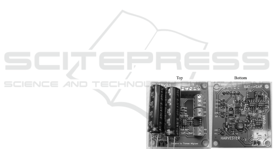
5 THE ENERGY HARVESTING
PROTOTYPE
After measuring the typical power consumption of
the UWASA Node and investigating what forms of
energy harvesting would be suitable, the energy
harvester prototype shown in Figure 2 was designed
and built. The design was made with modularity and
expandability in mind. The harvester was designed
to work with a small solar cell, but other sources can
be added in parallel if some modifications are made
(Höglund, 2014b).
Figure 2: Developed energy harvester prototype.
The chosen implementation is based on the
AmbiMax system described by Park and Chou
(2006). It is an entirely analog energy harvesting
system that was relatively efficient when it was
made in 2006, but the power consumption of
common, low-power digital controllers has since
dropped significantly, making them a viable
alternative. The maximum power point tracking was
not implemented in the same way in this project as
in the AmbiMax. The LTC3105 energy harvesting
IC was chosen to perform the harvesting. Since 2013
when this choice was made, some even more
Solar Energy Harvesting Solution for the Wireless Sensor Platform the UWASA Node
53
efficient energy harvesting ICs have become
available (Höglund, 2014b). The energy
management was designed with components similar
to those of the AmbiMax, but slightly more efficient
(Höglund, 2014b).
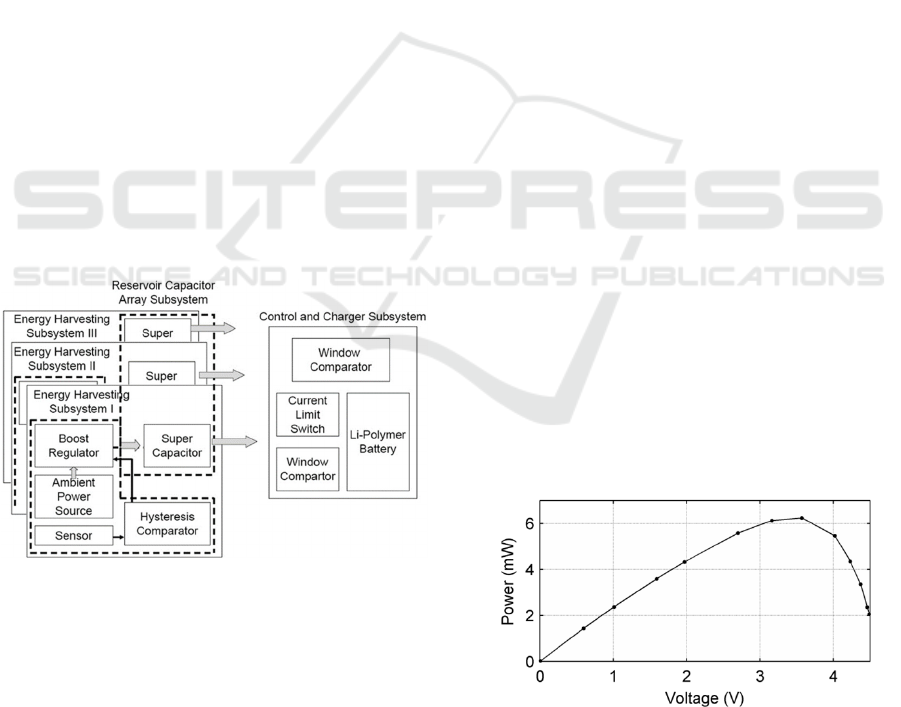
The architecture of the AmbiMax platform is
shown in Figure 3, reproduced from Park and Chou
(2006). It consists of a comparator with hysteresis
that performs MPPT with the aid of a sensor and
controls a boost regulator. The regulator charges a
supercapacitor that is connected to the voltage rail.
All of these components can be grouped as a
subsystem and used in parallel if more than one
energy source is used. The supercapacitors are
connected to the voltage rail via optional protection
circuitry, and the voltage rail powers the sensor
node. If the voltage of the voltage rail increases
above a certain threshold, the battery is charged
from the voltage rail via a current limiter.
Conversely, if the voltage of the voltage rail drops to
below a certain threshold, the battery feeds the
voltage rail as long as its voltage is above another
fixed threshold. This, in short, is how the AmbiMax
and the developed energy harvester work.
Additionally, a low-power undervoltage lock-out
circuit and a real-time clock-controlled latch switch
were designed to cut off the voltage rail from the
sensor node when it drops below a threshold or
when the node signals it to shut down for a length of
time; these were not part of the AmbiMax.
Figure 3: The architecture of the AmbiMax Platform (Park
and Chou, 2006).
The LTC3105 energy harvesting IC by Linear
Technology (Milpitas, California) was chosen from
many alternatives to be the energy harvester used in
the prototype of this work. It is listed as a 400 mA
step-up DC/DC converter with MPP control and 250
mV start-up voltage. It is capable of supplying up to
5.25 V. The prototype is designed to supply 4.2 V,
which is the maximum voltage of a one-cell lithium-
ion battery. The very low start-up voltage of the
LTC3105 allows it to harvest from a photovoltaic
cell that outputs a low voltage due to low ambient
illuminance. The low input voltage compatibility can
also be useful for other types of energy harvesting
sources such as thermoelectric, electromagnetic, or
magnetostrictive sources, which output a low
voltage.
6 THE SOLAR CELL
A 92 mm × 61 mm solar cell, with a nominal power
of 0.45 W, was chosen for the energy harvester
prototype, because its open circuit voltage is
approximately 5 V, which is suitable for the
LTC3105 and the battery, and its size is
approximately that of the UWASA Node’s. If more
energy is needed, it is possible to connect more than
one such solar cell in parallel with the other cells to
the energy harvester, while still keeping the MPP
voltage and energy harvesting circuit the same.
Protection diodes could be used to allow operation
with solar cells of higher voltages, but the LTC3105
operates most efficiently at input voltages slightly
lower than its output voltage, and therefore the MPP
voltage of the solar cell should be lower than the
desired output voltage.
In order to measure the MPP of the solar cell, it
was connected to a potentiometer used as a variable
load. It was then placed under a constant illuminance
of 2.8 klx and its output current and voltage were
measured while varying the load. The output power
was calculated, and the result is plotted in Figure 4.
The MPP occurs at approximately 3.6 V and 6.3
mW. The MPP varies slightly with the illuminance,
but after a few attempts at maximum power point
tracking, it was decided that a fixed MPP voltage is
sufficient for this application.
Figure 4: Power vs. voltage for the 0.45 W solar cell at 2.8
klx.
SENSORNETS 2016 - 5th International Conference on Sensor Networks
54

7 MAXIMUM POWER POINT
TRACKING
Maximum power point tracking (MPPT) aims to
adapt the energy harvesting load to the ambient
conditions so that the input voltage of the energy
harvester is always equal to the MPP voltage as it
varies, in effect performing impedance matching.
In the case of the LTC3105, the MPPT is
integrated on the chip and there is a pin named
MPPC. The LTC3105 keeps the source voltage the
same as the voltage on the MPPC pin, which
constantly outputs 10 µA. If MPPT is not necessary,
this pin can be connected via a fixed resistor R
MPPC
to ground in order to set the MPP to a fixed voltage
(U
MPPT
) according to (1). In the prototype, a 360 kΩ
resistor was used to achieve a U
MPPT
of 3.6 V.
U
MPPT
=10 µA* R
MPPC
(1)
The datasheet of LTC3105 proposes to use a diode
thermally coupled to the solar cell for MPPT, but
this is unlikely to work well over the large
temperature range of this application; it would also
be difficult to achieve thermal coupling.
MPPT could also be performed digitally by a
low-power microcontroller, digital signal processor,
or field-programmable gate array. It is easier to
calculate the MPP digitally and take several factors
into account, such as illuminance and temperature,
but unless such a digital control system is carefully
designed, not much power can be saved.
8 ENERGY MANAGEMENT AND
STORAGE
The energy management part of the circuit takes
care of routing the power in an optimal way between
the energy harvester and sensor node components
for maximum performance and optimal schedule of
operation. The energy management of the energy
harvester prototype consists of supercapacitors, a Li-
ion polymer battery, nanopower voltage
comparators, a logical AND gate, two MOSFETs
and a few current limiters.
The LiPo battery is charged by two
supercapacitors connected in series when the
supercapacitors reach a voltage threshold. The
charge current is limited by a current limiter that
also works as a switch. Charge current flows
intermittently due to a configured hysteresis, until
4.2 V is reached. The voltage thresholds at which
power is transferred in the prototype between the
supercapacitors, the battery, and the UWASA Node
are governed by LTC1540 nanopower voltage
comparators by Linear Technology (Milpitas,
California). These comparators feature an ultralow
quiescent current of nominally 0.3 µA, a voltage
reference, and a hysteresis, both adjustable by
resistor voltage dividers.
One comparator is used for activating the current
flow from the voltage rail (supercapacitor) to the
battery when the rail voltage is more than 3.7 V.
Another comparator is used in the undervoltage
lock-out (described in Section 8.3), and a pair of
comparators with an AND gate is used for activating
the current flow from the battery to the voltage rail.
All comparators were configured for a hysteresis of
approximately 100 mV.
The comparator that activates battery charging
and the AND gate that activates battery draining are
connected to the enable pins of two separate current
limiters that, when enabled, permit a limited current
flow through them in one direction. These current
limiters were implemented using TPS2030D power
distribution switches by Texas Instruments (Dallas,
Texas). They allow 300 mA to pass through them
when activated.
8.1 Supercapacitors
Supercapacitors can act as a buffer and be used to
store the first energy delivered by the energy
harvester until there is enough energy to begin
charging the battery or supplying the sensor node.
The voltage of the supercapacitor can rise quickly to
a voltage where the step-up (or step-down) converter
operates the most efficiently because of its much
lower capacity compared with a battery. Connecting
the harvester directly to the battery would cause its
voltage to rise very slowly and energy would be
harvested less efficiently because of the step-up
inefficiency at lower voltages. Supercapacitors can
also smooth out the wide dynamic range of energy
harvesters and the node load, especially if more than
one harvester subsystem is connected in parallel.
Another advantage of using supercapacitors is that
they can be used to preferentially supply the sensor
node before the battery is needed. This keeps the
battery voltage more even, which slows down
battery aging.
According to Mars (2009), (2) gives an
approximation for the necessary capacitance C of the
supercapacitor assuming there is a constant load
current I
L
and that the supercapacitor needs to be
able to supply I
L
for time t. When current is drawn
from a supercapacitor, there is an instantaneous
Solar Energy Harvesting Solution for the Wireless Sensor Platform the UWASA Node
55
voltage drop due to its equivalent series resistance
R
ESR
. The load voltage is allowed to decrease from
U
max
to U
min
. Equation (2) shows that an
approximately 12 F supercapacitor is necessary to
supply 250 mA for 60 seconds with the voltage
limits of the developed prototype. In the actual case,
the current would vary significantly over time, but
this equation provides a useful indication of how
large a capacitor is required.
C=
I
L
t
U
max
-U
min
-I
L
R
ESR
=
=
250*10
-3
A*60 s
4.2 V-2.9 V-250*10
-3
A*200
-3
Ω
=12 F
(2)
8.2 Switch Controlled by Real-Time
Clock
A real-time clock (RTC) was added to the prototype
so that the sensor node can cut off its own power
supply in order to avoid consuming any energy on
the node side while it is in sleep mode. The RTC has
an alarm output that can be set to trigger at the point
in time when the node should be powered on. The
RTC consumes only a few microamperes of current.
The alarm output is connected to a latch IC that
turns on or off the current flow through two
MOSFETs that supply the node with power. The
sensor node can request the RTC to activate the latch
at a specific time in the future, turning the power
supply on at that time, and then use the reset line of
the latch to shut itself down. An SHT11 temperature
and humidity sensor was also included on the PCB
on the same I
2
C bus as the RTC because temperature
and humidity measurements are needed in wind
turbine monitoring.
8.3 UnderVoltage Lock-Out Circuit
An undervoltage lock-out (UVLO) circuit was
designed to cut off the power from the sensor node
when the voltage rail is below 2.9 V. There is a 20
MΩ feedback resistor that creates an extra high
hysteresis of 350 mV to allow enough energy for the
sensor node to wake up and measure the voltage
without allowing the turn-on current surge and any
startup tasks to drain the voltage rail below the
UVLO threshold again. The switching is done using
a 2N7002 small signal N-channel MOSFET and an
IRLML6401 P-channel power MOSFET.
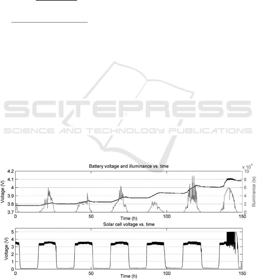
9 THE PERFORMANCE OF THE
PROTOTYPE
The lowest level of illuminance at which the
LTC3105 was able to harvest was a few hundred
lux, depending on the voltage of the supercapacitor.
The energy harvester prototype was tested in a long-
term test that lasted six continuous days. The solar
cell was located on a roof where it was not
shadowed by any object at any time of the day.
There was no load connected to the prototype. A
data logger was connected and used for measuring
time, illuminance, and the voltages of the
supercapacitor, battery, solar cell, and MPPC pin of
the LTC3105.
Figure 5: Energy harvester performance over six days.
SENSORNETS 2016 - 5th International Conference on Sensor Networks
56

During the test, the temperature was a few degrees C
below the freezing point. Figure 5 shows how the
prototype performed. On average, the energy
harvester was active for 9.0 hours per day (the sunny
hours) and harvested at 35.6 mW. On average, 1.16
kJ was harvested per day, or 2.14 J per minute
active. In 6 days, the total energy harvested was 6.9
kJ, which corresponds to 51% of the capacity of the
1,000 mAh, 3.7 V LiPo battery. Once the battery
was fully charged, the voltage rail reached the set
point of the energy harvesting circuit and the solar
cell was automatically disconnected, causing a
voltage of more than 5 V over the solar cell.
For most applications, one solar cell of the type
tested should be sufficient and the 1,000 mAh
battery capacity is useful to have to ensure the
sensor node can operate during days of low
illuminance. The solar cell, battery and energy
harvester of the prototype were well-dimensioned.
Regarding the energy consumption of the
UWASA Node, experiments showed that the startup
and initialization of wireless communication and a
few sensors consumes between 0.7 and 1.5 J.
Measuring three voltages 10,000 times using the
internal ADC consumes approx. 400 mJ (no
peripherals turned off). Transmitting 100 bytes of
data consumes ~850 mJ. Measuring 3-axis, 10-bit
acceleration at a sample rate of 500 Hz for 2 s
consumes 1.82 J. A typical program reading several
sensors at a high rate will consume approx. 3-10 J
for measurements and 50-100 J for transmission of
thousands of bytes. If few bytes are transmitted, the
node will consume less than 5 J and can thus operate
intermittently at an interval of 3-4 minutes on
harvested power.
10 CONCLUSIONS
The goal of this work was to build and test a small
energy harvester and power management prototype
optimized for the UWASA Node for outdoor use in
cold weather, primarily for wind turbine monitoring
applications. The developed energy harvester was
tested using only a solar cell, but the prototype was
designed so that more energy harvesting sources can
easily be added. Every part of the energy harvester
and power management was chosen to operate at
voltages optimal for the UWASA Node with power
module. The energy measurements presented in
Section 9 can be useful for energy harvester
developers. The presented prototype is an
improvement on the AmbiMax system described by
Park and Chou (2006). By integrating the RTC
switch on the energy harvesting PCB, the power
consumption of any connected sensor node can be
eliminated when inactive.
Powering the UWASA Node by energy
harvesting is a useful idea, as it makes the node self-
sufficient and allows it to operate in places where
servicing would be prohibitively expensive or
impossible. By using energy harvesters, wireless
sensor nodes can potentially operate independently
for several years, if the rest of the software and
hardware platform is sufficiently robust.
REFERENCES
Çuhac, C., 2012. UWASA Node Reference Manual 3.0.0.
[Unpublished, internal document]25 August. Aalto
University and University of Vaasa, ComSys group.
Gilbert, J.M. and Balouchi, F., 2008. Comparison of
Energy Harvesting Systems for Wireless Sensor
Networks. International Journal of Automation and
Computing, [online]. University of Hull. Available at:
<http://web.eecs.umich.edu/~prabal/teaching/eecs598-
w10/readings/GB08.pdf>.
Höglund, T., 2014a. Energy Harvesting for the UWASA
Wireless Sensor Node: Applications for Wind Turbine
Monitoring. B.Sc. University of Vaasa.
Höglund, T., 2014b. Energy Harvesting Solution for the
UWASA Node: Applications for Wind Turbine
Monitoring. M.Sc. University of Vaasa.
Mars, P., 2009. Using a Supercapacitor to Manage Your
Power. IDTechEx Ltd, [online]14 December.
Available at: <http://www.energyharvestingjournal.com/
articles/using-a-supercapacitor-to-manage-your-
power-00001921.asp>. [Accessed 24 August 2014].
Park, C. and Chou, P.H., 2006. AmbiMax: Autonomous
Energy Harvesting Platform for Multi-Supply
Wireless Sensor Nodes. Sensor and Ad Hoc
Communications and Networks, 2006. SECON '06.
2006 3rd Annual IEEE Communications Society,
[online]. Available through: IEEE Xplore Digital
Library website [Accessed 18 March 2013].
Virrankoski, R. (Ed.), Generic Sensor Network
Architecture for Wireless Automation (GENSEN),
Proceedings of the University of Vaasa, Reports 174,
Vaasa 2012.
Yigitler, H., Virrankoski, R. and Elmusrati, M.S.,
Stackable Wireless Sensor and Actuator Network
Platform for Wireless Automation: the UWASA Node,
Aalto University Workshop on Wireless Sensor
Systems, November 19th, 2010, Espoo, Finland.
Solar Energy Harvesting Solution for the Wireless Sensor Platform the UWASA Node
57
