
On the Use of OCT to Examine the
Varnish Layer of Paintings Cleaned with an Er:YAG Laser
Adele DeCruz
2
, Joseph A. Izatt
1
and Derek Nankivil
1
1
Department of Biomedical Engineering and the Fitzpatrick Center for Photonics,
Duke University, Durham, NC 27708, U.S.A.
2
Departments of Chemistry, Biology and the Fitzpatrick Center for Photonics,
Duke University, Durham, NC 27708, U.S.A.
Keywords: OCT, Varnish, Paintings, Er:YAG Laser, Conservation.
Abstract: Optical Coherence Tomography (OCT) was used to visualize and quantify the varnish layer of paintings.
And to verify the success of efforts by conservators to remove the varnish using laser ablation. An Er:YAG
laser (λ = 2.94μm) with a repetition rate of 15Hz and an optical power of 1mW was used to remove the
varnish. A spectral domain OCT system with a Michelson topology was constructed using a broadband
super-luminescent diode (λ = 840±25nm). The OCT system provided an 8µm resolution, and a field of view
of 5x5mm. Samples, including pigment, varnish and substrate, approximately 1mm
2
in size, were removed
from the oil painting, San Giorgio Maggiore by Martin Rico (1833-1908). Varnish thickness obtained from
OCT was validated by similar measurements obtained from SEM analysis. Other paintings, including a late
18
th
century landscape, signed Thomas Gainsborough, were imaged with OCT to compare neighboring
regions before and after laser treatment and to examine the layering of the artist’s signature in an effort to
determine its authenticity. In conclusion, the non-invasive OCT technique is an efficient tool for
measurement of varnish layer thickness, for imaging over-paint under varnish layers, and for assessing the
effectiveness of laser assisted varnish removal.
1 PURPOSE
The purpose of this study is to demonstrate that
Optical Coherence Tomography (OCT) can be used
to:
1) Measure the varnish layer thickness of paintings,
and
2) Verify that the varnish layer has been removed
after laser ablation-based conservation without
causing changes to the paint layers.
2 INTRODUCTION
To restore the original intent of the artist, art
conservation is moving towards an increased use of
laser ablation to remove varnish layers, which have
become encrusted with contaminants or have been
otherwise altered over the years
(Asmus, 1986);
Maravelaki et al., 1997); Georgious et al., 1998);
Kalaitzaki et al., 1999); Scholten et al., 2000);
(Klein et al., 2000); (De Cruz et al., 2000); (Branco
et al., 2003); (Pouli et al., 2008). It should be
possible to guide the restoration process with
imaging modalities that provide information about
the varnish layer. In paintings where the encrustation
has rendered the varnish completely opaque, OCT
has the potential to provide details about the
structure and thickness of the varnish layer in a non-
invasive manner
(liang et al., 2005); (Gora et al.,
2006).
3 BACKGROUND
Optical coherence tomography enables fast,
noninvasive, high resolution, three-dimensional
imaging of the internal microstructure of weakly
scattering objects. Conventional OCT systems are
coherence-gated interferometers wherein the optical
measurement technique known as low coherence
interferometry is used to measure the magnitude and
echo time delay of backscattered light. In its
simplest manifestation, time-domain OCT
(TDOCT), the illumination is split and sent to both a
DeCruz, A., Izatt, J. and Nankivil, D.
On the Use of OCT to Examine the Varnish Layer of Paintings Cleaned with an Er :YAG Laser.
DOI: 10.5220/0005729801070112
In Proceedings of the 4th International Conference on Photonics, Optics and Laser Technology (PHOTOPTICS 2016), pages 109-114
ISBN: 978-989-758-174-8
Copyright
c
2016 by SCITEPRESS – Science and Technology Publications, Lda. All rights reserved
109
reference arm and to the sample. Light returning
from the sample interferes with light returning from
the reference arm, and interference fringes are
observed provided that the reference and sample
path lengths are matched to within the coherence
length of the source. Scanning the reference path
length results in a series of interference fringes that
correspond to different depths in the sample. The
photo-detector signal is demodulated to reconstruct
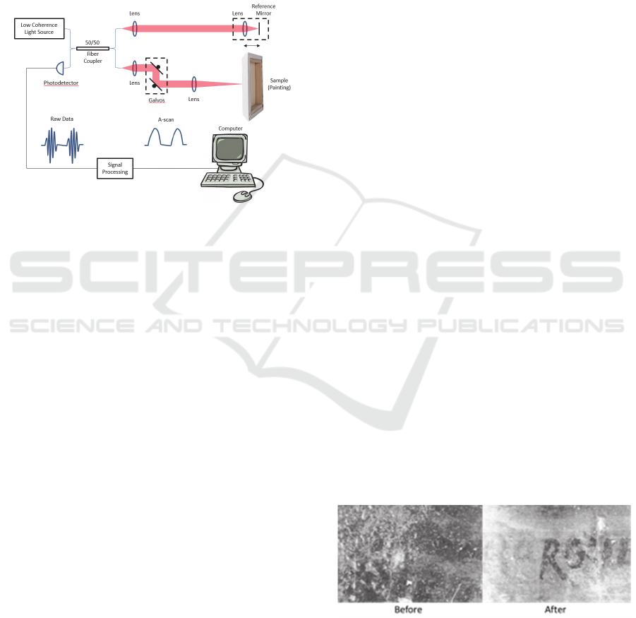
each A-scan (Figure 1).
Figure 1: Schematic of a fiber optic TDOCT system. Light
blue lines represent fiber optic paths, red lines represent
free space optical paths, and thin black lines represent
electronic signal paths.
Further, prior work (Figure 2) has shown that using
lasers for art conservation offer advantages over
conventional methods with solvents and scalpels
(Asmus, 1986); Maravelaki et al., 1997); Georgious
et al., 1998); Kalaitzaki et al., 1999); Scholten et al.,
2000); (Klein et al., 2000); (De Cruz et al., 2000);
(Branco et al., 2003); (Pouli et al., 2008). Some
contaminants and encrustations require very strong
solvents or cannot be removed with a solvent
without removing some of the paint itself. Moreover,
solvent may saturate the substrate, causing it to
swell, materials (from the substrate) may leach into
the solvent, and the conservator may be exposed to
toxic fumes from the solvent. A brief explanation of
the laser cleaning mechanism follows.
The Er:YAG laser, with a wavelength of 2.94
m,
coincides with a strong absorption peak in the
infrared spectra of OH- or NH-containing organic
molecules. The energy of photons at this wavelength
excites a bond vibrational stretching mode. Any
substance containing a high concentration of OH
bonds at its surface has a strong affinity for photons
at 2.94
m, and confines the absorption of these
photons to a surface depth of no more than a few
microns. A painting 's organic contaminant, which
either contains the OH bonds or has been treated
with a thin liquid film (water, alcohol, NH
4
+
, OH
-
)
immediately before lasing, acts as a stain of
relatively high concentration and very high
absorption, providing a natural barrier to energy
penetration into underlying layers.
The energy per photon of the Er:YAG radiation
is not sufficient to break bonds. The energy required
for OH bond dissociation in most organic molecules
ranges from 3.4 to 4.5 eV/molecule, while photons
of 2.94
m wavelength have an energy of only 0.4
eV. Furthermore, the irradiance of the laser is below
the level required to generate multi-photon effects,
which might provide the necessary dissociation
energy. The temperature rise due to cleaning with
the Er:YAG is principally limited to the affected
contaminant volume and reaches its vaporization
maximum of under a 100 °C for a few milliseconds
at most. The bulk of the laser energy goes into the
ejection of the heated contaminant from the paint
surface. The temperature rise in the underlying paint
layer is therefore small, and not sufficient to cause
thermal decomposition of most materials. As a
comparison, surface consolidation or the lining
processes often involve heating of the paint layer too
much higher temperatures for much longer time
periods.
The process as used (with adjustable moderate
pulse energies at a 15 Hz repetition rate) volatilizes
greases with high vapor pressure and can thus be
pictured as a type of steam distillation. Because of
the strong absorption, the photon energy is deposited
in a layer that is only a couple of microns thick on
the targeted surface. This energy goes into near-
instantaneous heating of the absorbing contaminant
through the vaporization of water or grease. The
rapid attendant rise in local pressure causes the
affected volume to be ejected forcefully from the
surface, taking much of the heat with it. As a result,
the underlying non-absorbent film does not undergo
significant heating, as estimated in a previous paper
(De Cruz et al., 2000); (DeCruz et al., 2014).
Figure 2: Micro-photo of the signature from an oil
painting, The Turkish Noble, by Charles Bargue (1825-
1883), date: 1859, showing part of the painter's signature
before and after laser treatment.
PHOTOPTICS 2016 - 4th International Conference on Photonics, Optics and Laser Technology
110
4 METHODS
In this study, OCT was used to visualize and
quantify the varnish layer of paintings. And to verify
the success of efforts by conservators to remove the
varnish layer using laser ablation. A free-running
Er:YAG (MonaLaser, Orlando, Florida) laser with a
central wavelength of 2.94 μm, a repetition rate of
15 kHz and an optical power of 1 mW was used to
remove the varnish. The IR light couples directly
into a 1-mm bore hollow glass fiber about 1-m long.
The other end of the fiber can be manipulated like a
pen.
A spectral domain OCT (SDOCT) system with a
Michelson topology was constructed using a
broadband super-luminescent diode (SLD-371,
Superlum, Carrigtwohill, Ireland) with a central
wavelength of 840 nm and a 50 nm bandwidth and a
line scan CMOS sensor (AViiVA, e2v Inc., Milpitas
CA) with a 20 kHz line rate. The sample arm design
utilized a 4f relay between the first and second
galvanometer (scanner) and a telecentric beam
delivery system to minimize optical distortions. The
OCT system provided an 8.5 µm axial and 7.5 µm
lateral resolution, a sensitivity of 105 dB, an
imaging range of 0.8 mm (6dB fall off) and a field
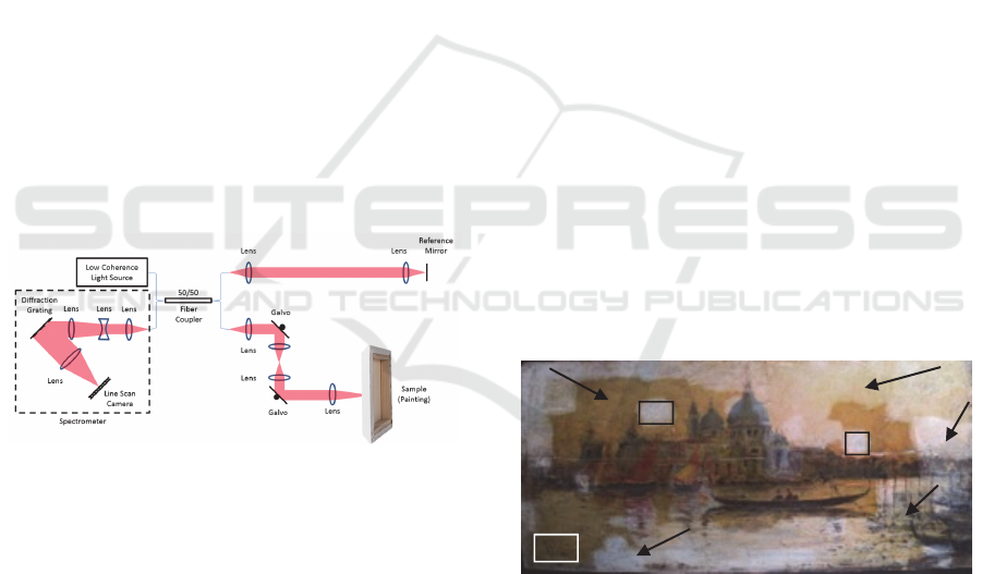
of view of 5 x 5 mm (Figure 3).
Figure 3: SDOCT system with Michelson topology.
SDOCT permits faster image acquisition and higher
signal-to-noise ratio than the predecessor TDOCT
technology. Through the use of spectral interferometry,
depth information is collected without movement of the
reference mirror. Backscattered light from the sample and
reference interfere, and the broadband interference pattern
is measured with the inverse Fourier transform of the
broadband interferogram. Thus, measurements of the
power spectral density of the interferogram as a function
of wavelength are obtained. Since the temporal coherence
function (also called the autocorrelation function) and the
power spectral density form a Fourier transform pair
(Wiener-Khinchin theorem), the A-scan can be
reconstructed by merely taking the inverse Fourier
transform of the broadband interferogram.
Samples, including pigment, varnish and substrate,
approximately 1 mm
2
in size, were removed from an
oil painting on panel (San Giorgio Maggiore) by
Martin Rico (1833-1908) and imaged using
Environmental Scanning Electron Microscopy
(ESEM). Varnish thickness obtained from OCT was
validated by similar measurements obtained from
ESEM.
In addition, other paintings, including a late 18
th
century landscape, signed Thomas Gainsborough,
were imaged with OCT to compare neighboring
regions before and after laser treatment and to
examine the layering of the artist’s signature in an
effort to determine its authenticity.
Two Bioptigen Envisu SDOIS (Spectral Domain
Ophthalmic Imaging System) systems were also
used: 1) R3500 2) R2300. The two systems utilize
different sources and spectrometer designs, but both
permitted visualization of varnish and paint, at
different depths. The 2300 has a lower imaging
depth but higher axial resolution, whereas the 3500
can image deeper with a slightly lower resolution. In
addition, the 2300 system has an 840 nm SLED,
whereas the 3500 has a 1064 nm SLED.
5 RESULTS
The painting San Giorgio Maggiore, Venice, by
Martin Rico (1833- 1908) with the signature, Rico in
the painting's lower left corner is covered by
discolored varnish (Figure 4). In the lighter areas,
the discolored yellow-orange varnish has been
removed with laser ablation.
Figure 4: San Giorgio Maggiore, Venice. Martin Rico
(1833-1908), oil on panel, 6x12” circa 1890; a) varnished
surface before cleaning; b) partially removed varnish; c)
surface with varnish completely removed; d) the signature
Rico covered by varnish.
The shallow penetration of the laser pulse enables
the conservator to remove varnish layers gradually
and this difference of thickness is illustrated in area
b in Figure 4: the varnish layer, microns thin, can be
imaged and measured by OCT (Figure 6).
In figure 5, the OCT scan of the painting layers
with near-infrared light creates a cross-sectional
a
b
c
c
c
c
b
d
On the Use of OCT to Examine the Varnish Layer of Paintings Cleaned with an Er:YAG Laser
111
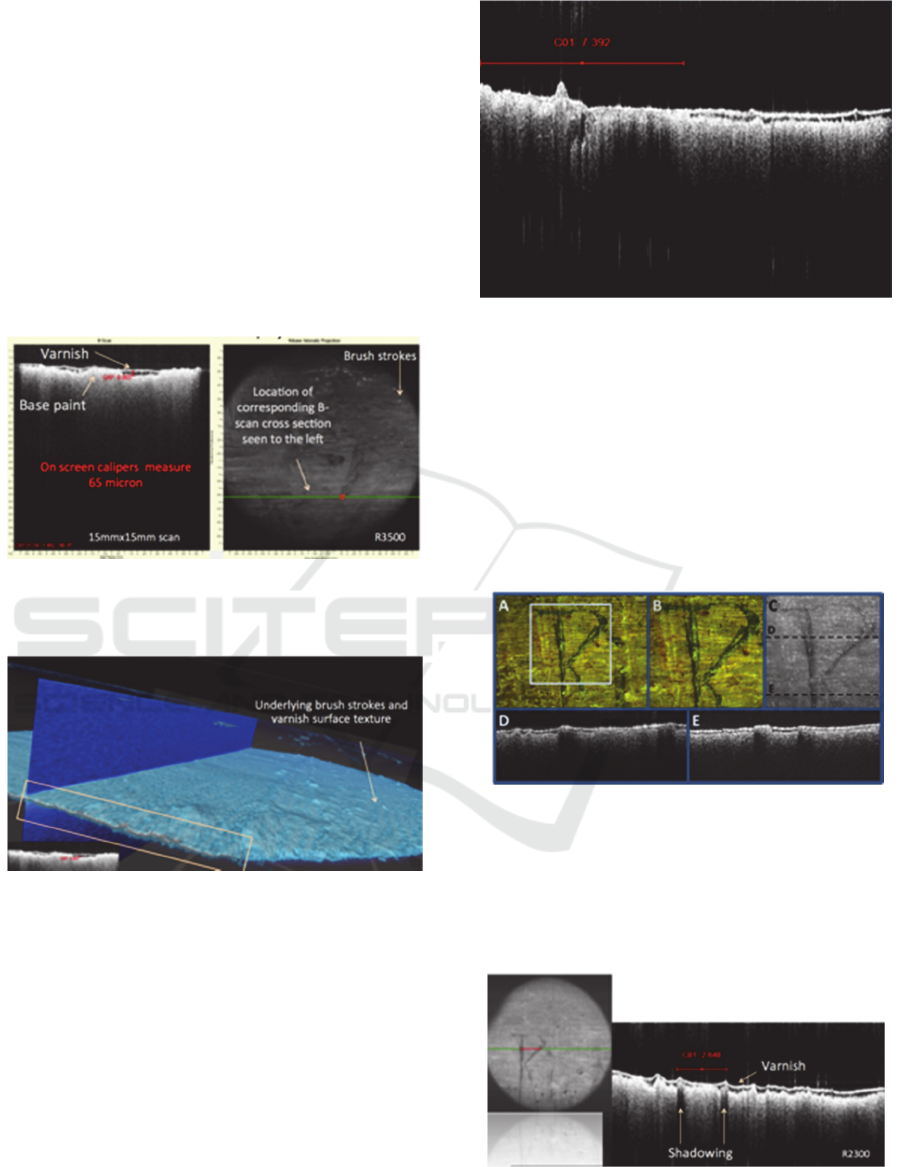
view as well as an en face projection of the surface.
The structure of the paint surface and the varnish
layer are clearly visible with the Envisu SDOIS
R3500. The first bright layer is the varnish-air
interface. The second bright layer is the varnish-
pigment interface. The black space in between is the
varnish itself, measured in one location using on
screen calipers as 65μm. The regions of differing
varnish thickness correspond to the variable texture
of the paint. Basically, in areas where the texture of
the paint made a void or valley, more varnish is
present (i.e. the varnish layer is thicker) and vice
versa in regions where the texture of the paint made
a mound or hill (Figure 7).
Figure 5: OCT B-scan (left) and volume intensity
projection (VIP) of San Giorgio Maggiore acquired with
the 3 μm axial resolution SDOIS R3500.
Figure 6: 3D rendering of the San Giorgio Maggiore
illustrating the underlying brush strokes and varnish
surface texture.
The 3D view (Figure 6), corresponding to the
images shown in Figure 5, confirms distinct
differences between varnish and paint layers.
The thinning of the varnish layer is confirmed in
Figure 7. The thickest layer of varnish is 64.3 m. In
the thinnest regions, the varnish is only 9.6 m
thick.
Interesting results were obtained of the signature
Rico in Figure 8 located in the painting's lower left
corner, which is covered with a thick layer of
discolored varnish.
Figure 7: Detail, Rico painting, area b of Figure 4. Left is
the thinned partially removed varnish layer (after laser
cleaning) and right is the varnish surface before laser
ablation.
The shallow depth of penetration of the Er:YAG
laser pulse at 2.94m is demonstrated in figure 9
The texture of the paint is preserved after lasing,
with no visible damage to individual brush strokes.
To the left in figure 9 is the varnish layer over the
paint. The right is the painting surface with the
varnish removed by laser ablation.
Figure 8: Images of the signature on an oil painting on
wood 19
th
century Venetian landscape panting by Rico.
Microscope images of the R in the signature acquired at 4x
magnification (A), close-up of R indicated by the light
blue box (B), OCT SVP of the same region shown in B
(C), OCT cross-sectional images show the layer of paint
under the varnish layer and over the painting’s surface (D
& E) acquired along the dotted lines shown in C.
Figure 9: Layers of darker pigmented paint can be
distinguished from subsurface paint layers (different
optical scattering and absorption properties), as well as the
presence of a distinct varnish layer. SDCIS R2300.
PHOTOPTICS 2016 - 4th International Conference on Photonics, Optics and Laser Technology
112
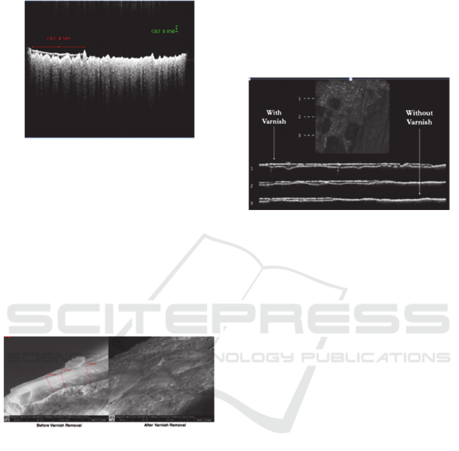
Figure 10: Detail of the varnish and paint surface of Rico
painting. Image taken with Bioptigen Envisu SDCIS
R2300.
SEM images before and after laser ablation are
reported in Figure 11. They were taken to verify the
accuracy of the OCT measurements as well as the
ablation efficiency.
The varnish layer thickness, on the left of Figure
11, was measured in three locations with the
following results: 13.09 μm, 11.87 μm and 13.24
μm. In the image acquired after Er:YAG laser
varnish removal, on the right of Figure 11, the
surface of the paint appears devoid of varnish, and
the texture of the surface of the painting appears
fluid-like with pockets of smoothed areas
Figure 11: ESEM images before (left) and after (right)
varnish removal. Note, ESEM imaging required removal
of a small (approximately 1 mm
2
) portion of the painting.
Visible under the varnish layer before varnish removal is
the paint layer.
Varnish layer thickness was 10.8 ± 3.8μm and 12.7
± 0.7μm measured by OCT and ESEM respectively.
Complete varnish layer removal was observed in
several regions of the paintings after laser treatment
with occasional residual varnish in regions of
significant surface topological variation.
Additionally, the presence of over-paint and
differences in penetration depth were observed in the
OCT cross-sections (Figure 7).
In Figure 12, the summed voxel projection
(SVP) (top) shows ablation craters in the varnish
layer on the left. In addition, the corresponding OCT
cross-sections taken at locations 1-3 (bottom) are
shown. Notice that there is less varnish with each
retreating edge of the varnish layer (from 1 to 3),
which has been removed with the Er:YAG laser in
each cross-section.
Figure 12: A late 18th century landscape, signed Thomas
Gainsborough, imaged in a region with and without
varnish.
6 CONCLUSIONS
We believe that this is the first demonstration of the
application of OCT to show that the varnish is
removed by Er:YAG laser treatment. Given the
apparently preserved texture of the underlying
pigment after laser treatment, these results suggest
that the laser radiation does not penetrate
significantly into the paint layer.
In conclusion, we demonstrated that OCT may
provide a non-invasive technique that offers
measures of the varnish layer thickness and
verification of its removal after laser ablation-based
conservation efforts.
ACKNOWLEDGEMENTS
This project was funded by the Fitzpatrick
Foundation (Scholar - DN), the Michael J.
Boberschmidt Fund, and the Ottmar Foundation.
REFERENCES
Asmus JF, More light for art conservation, IEEE Circuits
and Devices, March: p. 6,1986.
Maravelaki PV, Zafiropulos V, Kylikoglou V, Kalaitzaki
M, Fotakis C. Laser induced breakdown spectroscopy
as a diagnostic technique for the laser cleaning of
On the Use of OCT to Examine the Varnish Layer of Paintings Cleaned with an Er:YAG Laser
113

marble. Spectrochim. Acta B, 52:41, 1997.
Georgiou S, Zafiropulos V, Anglos D, Balas 3. C, Tornari
V, Fotakis C. Excimer laser restoration of painted
artworks: procedures, mechanisms and effects. Appl.
Surf. Sci., 127–129,:738, 1998.
Kalaitzaki P, Zafiropulos V, Fotakis C. Excimer laser
cleaning of encrustation on pentelic marble: procedure
and evaluation of the effects. Appl. Surf. Sci., 148:92,
1999.
Scholten JH, Teule JM, Zafiropulos V, Heeren RMA.
Controlled Laser cleaning of painted artworks using
accurate beam manipulation and on-line LIBS-
detection, J. Cult. Heritage, 1:S215, 2000.
Klein S, Stratoudalsi T, Marakis Y, Zafiropulos V,
Dickmann K. Comparative study of different
wavelengths from IR to UV applied to clean
sandstone. Appl. Surf. Sci., 157:1, 2000.
De Cruz A, Wolbarsht ML, Hauger SA. Laser removal of
contaminants from painted surfaces, J. Cult. Heritage,
1:S173, 2000.
Bracco P, Lanterna G, Matteini M, Nakahara K, Sartiani
O, De Cruz A, Wolbarsht ML, Adamkiewicz E, and
Colombini MP. Er:YAG laser: an innovative tool for
controlled cleaning of old paintings: testing and
evaluation. J. Cult. Heritage, 4:202s-208s, 2003.
Pouli P, Paun I-A, Bounos G, Georgiou S, Fotakis C. The
potential of UV femtosecond laser ablation for varnish
removal in the restoration of painted works of art.
Appl. Surf. Sci., 254:6875-6879, 2008.
Liang H, Cid MG, Cucu RG, Dobre GM, Podoleanu AG,
Pedro J, Saunders D. En- face optical coherence
tomography – a novel application of non-invasive
imaging to art conservation. Optics Express,
13;16:6133-6144, 2005.
Gora M, Targowski P, Rycyk A, Marczak J. Varnish
ablation control by optical coherence tomography.
Laser Chemistry, 2006.
DeCruz A, Andreotti A, Ceccarini A.Colombini MP.
Laser cleaning of works of art: evaluation of the thermal
stress induced by Er:YAG laser. Applied Physics B,
2014.
PHOTOPTICS 2016 - 4th International Conference on Photonics, Optics and Laser Technology
114
