
Guided Filtering using Reflected IR Image for Improving Quality
of Depth Image
Takahiro Hasegawa, Ryoji Tomizawa, Yuji Yamauchi, Takayoshi Yamashita and Hironobu Fujiyoshi
Chubu University, 1200, Matsumoto-cho, Kasugai, Aichi, Japan
Keywords:
Guided Filter, Reflected IR Image, Depth Image, Denoising, Upsampling.
Abstract:
We propose the use of a reflected IR image as a guide image to improve the quality of depth image. Guided
filtering is a technique that can quickly remove noise from a depth image by using a guide image. However,
when an RGB image is used as a guide image, the quality of depth image does not be improved if the RGB
image contains texture information (such as surface patterns and shadows). In this study, our aim is to obtain
a depth image of higher quality by using a guide image derived from a reflected IR image, which have less
texture information and a high correlation with depth image. Using reflected IR image, it is possible to perform
filtering while retaining edge information between objects of different materials, without being affected by
textures on the surfaces of these objects. In evaluation experiments, we confirmed that a guide image based on
reflected IR image produce better denoising effects than RGB guide image. From the results of upsampling
tests, we also confirmed that the proposed IR based guided filtering has a higher PSNR than that of RGB
image.
1 INTRODUCTION
Time-of-flight (TOF) cameras (Lange and Seitz,
2001) are widely used in computer vision as sensors
for the acquisition of depth information (May et al.,
2006) (Fang et al., 2009). In particular, Kinect cam-
eras have been used to estimate human poses from a
depth image as a gesture input for computer games
(Shotton et al., 2011). A TOF camera measures the
distance to an object by using phase differences to
determine the time it takes for infrared light from an
LED to be reflected back to the camera from an ob-
ject (Hansard et al., 2013) (Foix et al., 2011). How-
ever, depth image from a TOF camera is susceptible
to noise from external light disturbance due to the fact
that the energy of infrared photons decreases as their
time of flight increases. Since a noisy depth image can
lead to impaired object recognition and object detec-
tion performance (Ikemura and Fujiyoshi, 2012), pre-
processing measures such as noise removal are nec-
essary. Also, a depth image is generally of low reso-
lution due to hardware constraints on camera sensors
(Kolb et al., 2009), but a higher resolution image is
needed in many applications.
Noise elimination and upsampling from depth im-
age are achieved by Gaussian filter, bilateral filter
(Tomasi, 1998), non-local means filter (Buades et al.,
2005) and guided filter (Kaiming et al., 2013). Al-
though a Gaussian filter reduces noise, it also smooths
out the required edges between objects. A joint bi-
lateral filter (Petschnigg et al., 2004) (Eisemann and
Durand, 2004) is an enhanced form of bilateral fil-
ter that uses two types of image a noisy input image
and a reference image with reduced noise to remove
noise from the input image by filtering determined
based on the pixel values of the reference image. A
bilateral filter and a joint bilateral filter are used to
upsample the depth image (Yang et al., 2007) (Kopf
et al., 2007). While a bilateral filter and joint bilat-
eral filter are capable of smoothing out images while
preserving edges, its high computational cost results
in problems due to slow processing times. A non-
local means filter (Buades et al., 2005) creates a lo-
cal region for each pixel of an image as a template.
It also defines a support window that is wider than
the template region. The weights of the support win-
dow are decided by similarity of template matching.
A non-local means filter effectively removes noise
from the image by convoluting it with support win-
dows calculated for each pixel. Furthermore, a non-
local means filter is used for upsampling of depth im-
ages (Park et al., 2011). However, it has a high com-
putational cost because the support window is calcu-
lated for each pixel. A guided filter (Kaiming et al.,
2013) is a filter that removes noise by using an im-
Hasegawa, T., Tomizawa, R., Yamauchi, Y., Yamashita, T. and Fujiyoshi, H.
Guided Filtering using Reflected IR Image for Improving Quality of Depth Image.
DOI: 10.5220/0005717800330039
In Proceedings of the 11th Joint Conference on Computer Vision, Imaging and Computer Graphics Theory and Applications (VISIGRAPP 2016) - Volume 3: VISAPP, pages 35-41
ISBN: 978-989-758-175-5
Copyright
c
2016 by SCITEPRESS – Science and Technology Publications, Lda. All rights reserved
35
age captured in the same scene as the input image. A
guided filter uses edge information from a guide im-
age, which enables it to preserve edges in the depth
image. It also has a low computational cost, and can
thus be processed at high speed. Furthermore, given
a high-resolution guide image, it can also upsample
a low-resolution input image by interpolation. How-
ever, when an RGB image is used as the guide image,
the depth image can become degraded due to texture
information (object patterns, shadows, etc.) that is not
present in the depth image.
In this paper we propose enhancing a depth im-
age by guided filter using a reflected infrared (IR) im-
age.
A reflected IR image is obtained by intensity
value which reflected infrared light from an object. A
reflected IR image has no unnecessary texture infor-
mation and is strongly correlated with the depth im-
age, because it uses reflection of infrared light as with
depth image. Therefore, the proposed method pro-
duces a high-quality depth image that is unaffected by
texture information by using reflected IR image. The
remainder of the paper is organized as follows. Sec-
tion 2 discusses conventionalguided filtering. Section
3 introduces the proposed method. Section 4 presents
the experimental results, and the paper is concluded
in the section 5.
2 GUIDED FILTER
This section discusses the guided filtering process,
and the denoising and upsampling performed using
a guided filter.
2.1 Guided Filtering Process
A guided filter is an edge-preserving noise removal
filter that filters a depth image by using a guide image
captured in the same scene as the target depth image.
This is based on the idea that the output image of a
guided filter is represented by a linear transform of
the guide image. The processing flow of a guided fil-
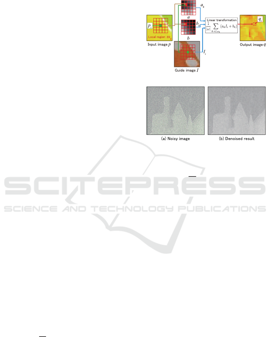
ter is shown in Figure 1. In a local region ω
k
, the
coefficients (a
k
, b
k
) used for linear transformation are
optimized so as to minimize the following cost func-
tion E:
E(a
k
, b
k
) =
1
ω
k
∑
i
((a
k
I
i
+ b
k
− p
i
)
2
+ εa
2
k
), (1)
where ε is a smoothing coefficient, ω is the local re-
gion, I
i
represents the pixel values of the guide im-
age, and p
i
represents the pixel values of the input
image. The resulting coefficients (a
k
, b
k
) are used to
Figure 1: Guided filter processing.
Figure 2: Denoising with a guided filter.
estimate the output image pixels q
i
according to the
linear transform of Equation (2):
q
i
=
1
|ω|
∑
k:i∈ω
k
(a
k
I
i
+ b
k
). (2)
2.2 The Issues of Guided Filtering
The guided filtering is used for denoting and up sam-
pling. Like a bilateral filter, a guided filter is able to
remove noise while preserving edges. In a bilateral
filter, noise is removed by using information from the
input image alone. But in a guided filter, it is possible
to remove noise more efficiently by adding the infor-
mation of a noiseless guide image. Figure 2 shows an
example of denoising applied to a noisy depth image.
A guided filter makes it possible to perform upsam-
pling using a guide image of higher resolution than
the input image. For a low-resolution input image, all
the pixel coefficients(a
k
, b
k
) from the guideimage are
calculated, and for pixels that do not have the signal
components of the input image, the pixel values are
calculated according to Equation (2). In this way, it is
possible to perform upsampling by interpolating from
a low-resolution image. Figure 3 shows an example
where a 320×240 pixel depth image is upsampled to
640×480 pixels by using a guided filter.
Although a guided filter can perform edge-
preserving filter processing, problems can arise when
a RGB image is used as the guide image due to the
effects of textures that are not present in the depth im-
age, as shown in Figure 4. This is because filtering is
VISAPP 2016 - International Conference on Computer Vision Theory and Applications
36
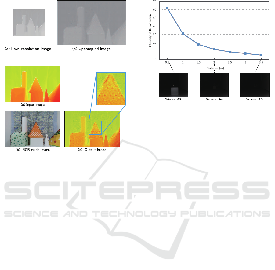
Figure 3: Upsampling with a guided filter.
Figure 4: Result of guided filtering using an RGB guide
image.
performed using texture information that is not origi-
nally present in the depth image.
3 GUIDED FILTERING USING A
REFLECTED IR IMAGE
In this study, we use a reflected IR image obtained
from TOF camera which is used for computing depth
information, in order to prevent the depth image from
being spoiled by the effects of unwanted texture in-
formation. This section examines the characteristics
of infrared light and discusses the proposed method
of using a reflected IR image.
3.1 Characteristics of Reflected
Infrared Light
Intensity of IR reflection varies according to the dis-
tance to the object, the orientation of the reflecting
surfaces, and the object’s material. In this section, we
examine the characteristics of reflected IR.
3.1.1 Characteristics of Change with Depth
The pixel values of the reflected IR image are the re-
flection values of infrared light, which vary with the
object’s depth from the camera. Figure 5 shows how
the reflected IR values vary with depth. According to
Figure 5: Variation of reflection intensity with depth.
Figure 5, at depths of over 2 m, the reflected IR values
become so small that objects cannot be distinguished
in the resulting image. If this is used as a guide im-
age, then pixels captured from objects distant from
the camera will be of no use for filtering.
3.1.2 Characteristics of Reflecting Surface
Orientation
When the orientation of the reflecting surface of the
object changes, the amount of light reflected also
changes significantly. Figure 6 shows how the re-
flected IR changes with the angle of the reflecting sur-
face of objects placed at equal depths. From Figure 6,
it can be seen that as the angle of the reflecting sur-
face increases, the reflected IR is attenuated. If this is
used as a guide image, then no filtering effect will be
obtained in pixels where the reflecting surface has a
large angle.
3.1.3 Characteristics of the Material
The reflection of light varies according to the reflec-
tion characteristics of the object’s material. Figure 7
shows the different IR reflection intensities of mate-
rials placed at the same distance with their reflecting
surfaces at an angle of 0
◦
. From this figure, it can
be seen that the reflected IR varies with the object’s
material. However, since estimating materials is gen-
erally a difficult problem, in this study we do not con-
sider changes of material.
3.2 Using Reflected IR Image
By performing guided filtering using a reflected IR
image, we can obtain a high-quality depth image. A
reflected IR image is suitable as a guide image for
guided filtering because it has no textures of patterns
Guided Filtering using Reflected IR Image for Improving Quality of Depth Image
37
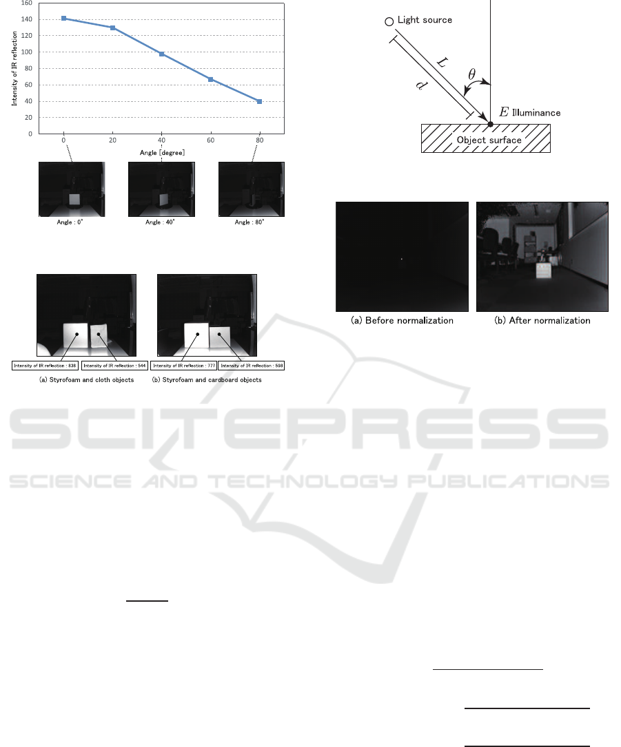
Figure 6: Variation of reflection intensity with the angle of
the reflecting surface.
Figure 7: Variation of reflected IR with material.
that are included in an RGB image, and is strongly
correlated with the depth image. However, since a
reflected IR image has the characteristics shown in
subsection 3.1, it is not possible to use the raw data
directly as a guide image. Therefore, the reflected IR
image is normalized to take these characteristics into
account. The illuminance E of light L from the light
source at the object surface is known to attenuate ac-
cording to the depth d of the object and the angle θ of
the light, as shown in Figure 8.
E =
L
(2∗d)
2
cosθ (3)
In this study, the reflected IR image is normalized us-
ing the object’s depth and the angle of the reflecting
surface.
3.2.1 Normalization According to Depth
Since the infrared light from a TOF camera attenuates
with increasing depth as shown in Equation (3), the
reflected IR decreases. Therefore, the depth data is
used to normalize the reflected IR image according to
Equation (4):
G(i, j) = I(i, j) ∗(2∗d(i, j))
2
, (4)
where d(i, j) is the distance value at coordinates (i, j),
and G is the reflected IR image after normalization.
Figure 8: Attenuation of light according to the object depth
and light angle.
Figure 9: Normalization according to depth.
Since light is attenuated in proportion to the square
of the depth, we can use Equation (4) to restore the
reflected IR values. Figure 9 shows an example of a
reflected IR image normalized using Equation (4).
3.2.2 Normalization According to Depth and
Reflecting Surface Orientation
The intensity values of the reflected IR image vary ac-
cording to the orientation of the reflecting surfaces of
the objects. Therefore, the reflected IR image is nor-
malized using the reflecting surface orientation calcu-
lated from the depth image. From Equation (3), nor-
malization according to the orientation of the reflect-
ing surfaces at the angle of coordinate (i, j) is per-
formed as shown in Equation (5). Guided filtering is
then performed using the reflected IR image normal-
ized in this way as a guide image.
G(i, j) =
I(i, j) ∗(2∗d(i, j))
2
cosθ
x
∗cosθ
y
(5)
θ
x
(i, j) = tan
−1
d(i+ 1, j) −d(i−1, j)
(i+ 1) −(i−1)
(6)
θ
y
(i, j) = tan
−1
d(i, j + 1)−d(i, j −1)
( j + 1) −( j −1)
(7)
θ
x
and θ
y
are the angles of the reflecting surface in
the x and y directions as estimated from the neigh-
boring pixels in the reflected IR image. According
to Equation (5), the image is simultaneously normal-
ized based on the camera-to-object depth d(i, j) and
the reflecting surface orientation θ
x
and θ
y
. Figure
VISAPP 2016 - International Conference on Computer Vision Theory and Applications
38
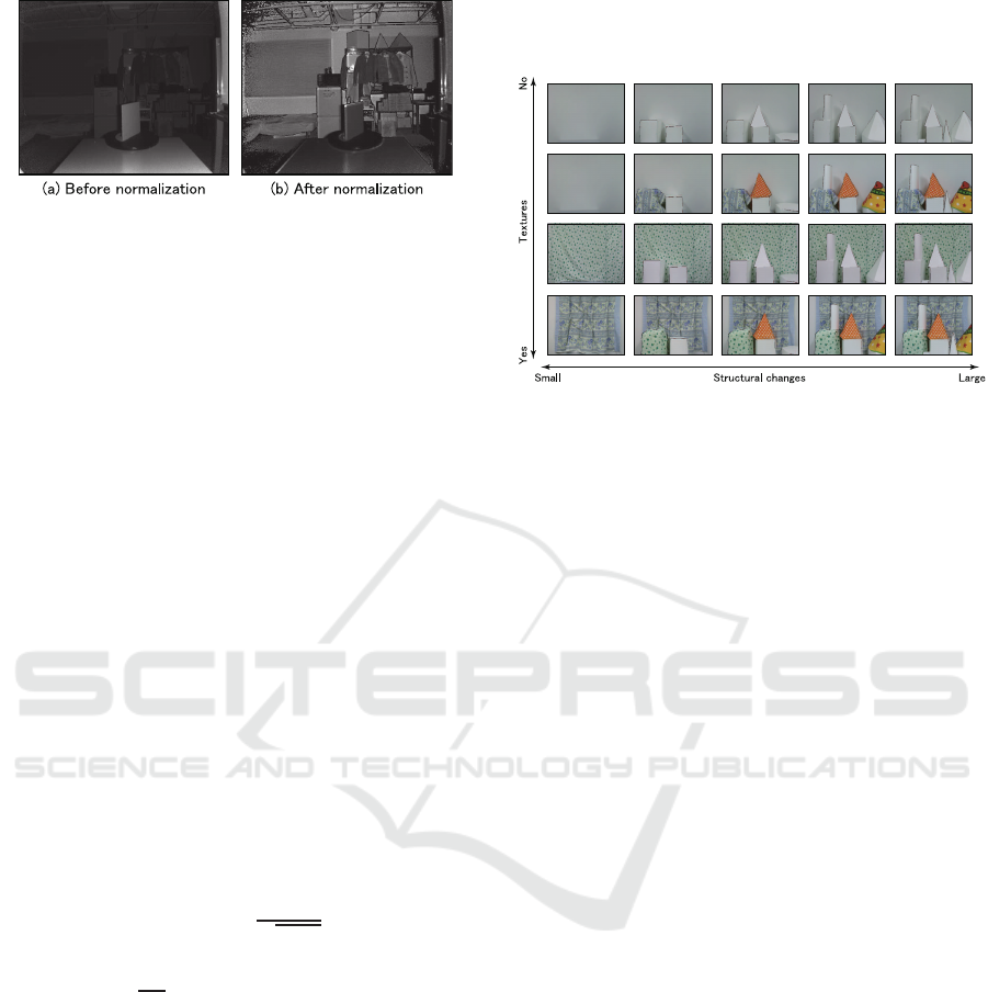
Figure 10: Normalization according to depth and reflecting
surface orientation.
10 shows an example of a reflected IR image where
the depth and reflecting surface orientations have been
normalized simultaneously. By performing normal-
ization according to the orientation of reflecting sur-
faces, it is possible to suppress the attenuation of re-
flected IR according to the orientation of the subject
surfaces.
4 EXPERIMENTAL RESULTS
We performed evaluation tests to demonstrate the ef-
fectiveness of guided filtering using a reflected IR im-
age. These tests were focused on denoising and up-
sampling.
4.1 Experimental Overview
In this experiments, we compared the proposed
method (IR guide) with a conventional method (RGB
guide) using a guide filter with an RGB image as the
guide. The evaluation was performed using the peak
signal-to-noise ratio (PSNR) obtained from the fol-
lowing equation:
PSNR = 20log
10
MAX
√
MSE
[dB], (8)
MSE =
1
mn
m−1
∑
i=0
n−1
∑
j=0
(X(i, j) −X
′
(i, j))
2
, (9)
where MAX is the maximum value that can be ob-
tained among the true pixel values (m×n pixels), and
MSE is the mean square error between the original
pixels X and the filtered pixels X
′
. For the true values,
we used the output of a 5×5 median filter applied to
the depth image. The images used in the tests con-
sisted of 178 images of the structure shown in Figure
11 with various different textures. The images were
all 512×424 pixels in size.
In the denoising tests, Gaussian noise (mean = 0,
σ = 0.02) was added to the depth image in order to
confirm the noise removal effects. In the upsampling
tests, the depth images were reduced to one quar-
ter of their original size simply by decimating pixels.
We then evaluated the results of upsampling these re-
duced images.
Figure 11: Evaluation data set.
4.2 Evaluation of Denoising Effects
Table 1 shows the PSNR of each method in the de-
noising tests. From Table 1, it can be confirmed that
the PSNR values of the normalized reflected IR image
are larger than those of images obtained using RGB
guide images or median filtering. The reflected IR im-
ages obtained by normalizing both for depth and ori-
entation of reflecting surfaces resulted in PSNR val-
ues that were slightly lower than those obtained with
reflected IR images normalized for depth alone. This
is because that noise added to the depth image causes
instability in the estimation of the reflecting surface
angles θ
x
and θ
y
. Figure 12 shows an example of a
guided filter being used to remove noise from a depth
image with added noise. From Fig. 12, it can be con-
firmed that an IR guide image was better than an RGB
guide image for removing noise while suppressing the
effects of textures on the object surface.
4.3 Evaluation of Upsampling Effects
Table 2 shows the PSNR of each method in upsam-
pling. Like with denoising, it can be seen that the nor-
malized reflected IR image resulted in higher PSNR
values than the conventional RGB image. Also, the
reflected IR images obtained by normalizing both for
depth and orientation of reflecting surfaces resulted
in PSNR values that were equal to or higher than
those obtained with reflected IR images normalized
for depth alone. This is thought to be because when
the effects of noise on the input image were small,
the angles θ
x
and θ
y
of the object’s reflecting surface
were estimated stably so that the PSNR was increased
by including normalization according to the reflecting
surface orientation.
Figure 13 shows examples of low-resolution
Guided Filtering using Reflected IR Image for Improving Quality of Depth Image
39
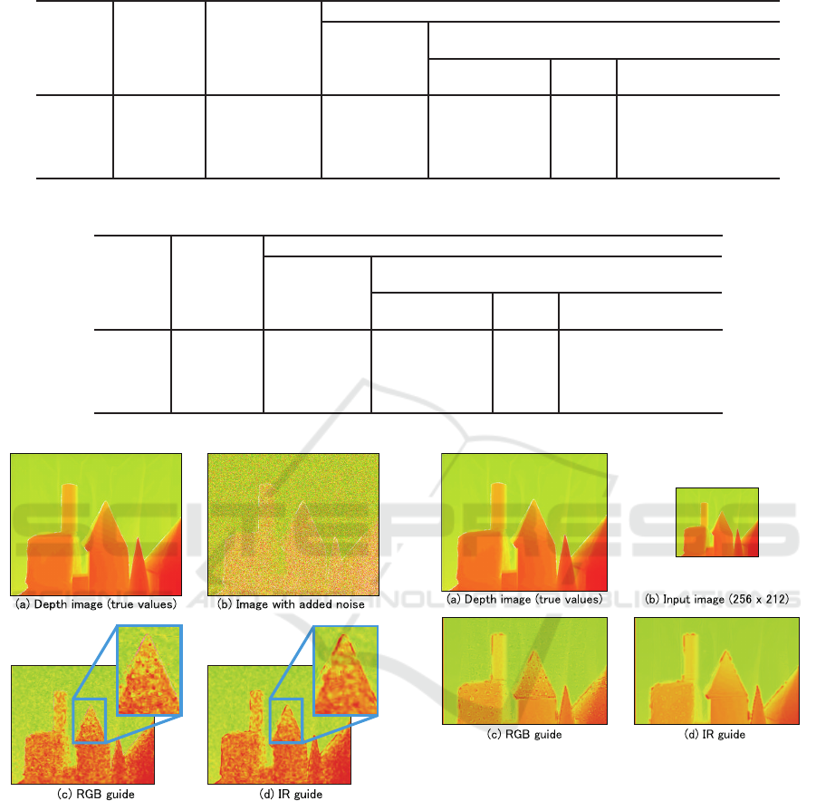
Table 1: PSNR of each method in denoising [dB].
Guided image
Texture
Structural
changes
Median filter RGB image reflected IR image
Without
normalization
Depth Depth + orientation
No Small 30.85 32.76 23.43 34.92 34.86
Yes Small 30.57 32.51 23.37 34.91 34.78
No
Large 30.29 32.22 23.26 34.27 34.19
Yes Large 30.14 31.96 23.19 34.23 34.17
Table 2: PSNR of each method in upsampling [dB].
Guided image
Texture
Structural
changes
RGB image reflected IR image
Without
normalization
Depth Depth + orientation
No Small 19.76 8.43 20.64 20.67
Yes Small 19.62 8.37 20.60 20.62
No
Large 19.48 8.26 20.18 20.23
Yes Large 19.27 8.19 20.18 20.16
Figure 12: Examples of noise elimination with guided fil-
ters.
depth images upsampled by guided filters. From Fig.
13, it can be seen that it was possible to restore a 1/4
size image to its original size. When using an RGB
guide image, the object’s surface texture is left be-
hind in the upsampled image, but with a reflected IR
image, it can be seen that the depth image is almost
completely unaffected by texture.
Figure 13: Examples of upsampling with guided filters.
5 CONCLUSIONS
We have produced a depth image of higher qual-
ity by introducing the use of reflected IR image in
guided filters. We have confirmed that a greater de-
noising effect can be achieved by normalizing a re-
flected IR image according to the depth of objects
than by guided filtering using a conventionalRGB im-
age as the guide. Also, when a depth image with low
noise is upsampled, we confirmed that it is possible
to achieve higher quality upsampling by using a re-
flected IR image that has been normalized by depth
and by the orientation of the reflecting surfaces. In
the future works, we confirm effectiveness of the pro-
VISAPP 2016 - International Conference on Computer Vision Theory and Applications
40

posed method by comparing other filtering algorithms
such as non-local means filter (Buades et al., 2005)
and bilateral filter (Tomasi, 1998). Also, we will
study how to exploit the benefits of each type of im-
age to achieve higher quality by combining an RGB
image and a reflected IR image.
REFERENCES
Buades, A., Coll, B., and Morel, J. M. (2005). A Non-
Local Algorithm for Image Denoising. In Conference
on Computer Vision and Pattern Recognition, pages
60–65.
Eisemann, E. and Durand, F. (2004). Flash Photography
Enhancement via Intrinsic Relighting. ACM Transac-
tions on Graphics, 23(3):673–678.
Fang, Y., Swadzba, A., Philippsen, R., Engin, O., Hanheide,
M., and Wachsmuth, S. (2009). Laser-based naviga-
tion enhanced with 3d time-of-flight data. In Robotics
and Automation, 2009. ICRA ’09. IEEE International
Conference on, pages 2844–2850.
Foix, S., Alenya, G., and Torras, C. (2011). Lock-in Time-
of-Flight (ToF) Cameras: A Survey. IEEE Sensors
Journal, 11(9):1917–1926.
Hansard, M., Lee, S., Choi, O., and Horaud, R. (2013).
Time-of-Flight Cameras - Principles, Methods and
Applications. Springer Briefs in Computer Science.
Springer.
Ikemura, S. and Fujiyoshi, H. (2012). No TitleHuman De-
tection by Haar-like Filtering using Depth Informa-
tion. In International Conference on Pattern Recog-
nition, pages 813–816.
Kaiming, H., Jian, S., and Xiaoou, T. (2013). Guided Image
Filtering. IEEE Transactions on Pattern Analysis and
Machine Intelligence, 35(6):1397–1409.
Kolb, A., Barth, E., Koch, R., and Larsen, R. (2009). Time-
of-Flight Cameras in Computer Graphics. Computer
Graphics Forum.
Kopf, J., Cohen, M. F., Lischinski, D., and Uyttendaele, M.
(2007). Joint Bilateral Upsampling. ACM Transac-
tions on Graphics, 26(3).
Lange, R. and Seitz, P. (2001). Solid-State Time-of-Flight
Range Camera. IEEE Journal of Quantum Electron-
ics, 37(3):390–397.
May, S., Werner, B., Surmann, H., and Pervolz, K. (2006).
3D time-of-flight cameras for mobile robotics. In In-
ternational Conference on Intelligent Robots and Sys-
tems, pages 790–795.
Park, J., Kim, H., Tai, Y.-W., Brown, M., and Kweon, I.
(2011). High Quality Depth Map Upsampling for 3D-
TOF Cameras. In International Conference of Com-
puter Vision.
Petschnigg, J., Szeliski, R., Agrawala, M., Cohen, M.,
Hoppe, H., and Toyama, K. (2004). Digital photogra-
phy with flash and no-flash image pairs. ACM Trans-
actions on Graphics, 23(3):664–672.
Shotton, J., Fitzgibbon, A., Cook, M., Sharp, T., Finocchio,
M., Moore, R., Kipman, A., and Blake, A. (2011).
Real-Time Human Pose Recognition in Parts from
Single Depth Images. In Conference on Computer Vi-
sion and Pattern Recognition, volume 2, pages 1297–
1304.
Tomasi, C. (1998). Bilateral Filtering for Gray and Color
Images. In International Conference on Computer Vi-
sion, pages 839–846.
Yang, Q., Yang, R., Davis, J., and Nister, D. (2007). Spatial-
Depth Super Resolution for Range Images. In Con-
ference on Computer Vision and Pattern Recognition,
pages 1–8.
Guided Filtering using Reflected IR Image for Improving Quality of Depth Image
41
