Fast and Accurate Face Orientation Measurement in Low-resolution
Images on Embedded Hardware
Dries Hulens, Kristof Van Beeck and Toon Goedem
´
e
EAVISE, KU Leuven, Sint-Katelijne-Waver, Belgium
Keywords:
Face Angle Estimation, Gaze Direction, Pose Estimation, Embedded Hardware.
Abstract:
In numerous applications it is important to collect information about the gaze orientation or head-angle of a
person. Examples are measuring the alertness of a car driver to see if he is still awake, or the attentiveness
of people crossing a street to see if they noticed the cars driving by. In our own application we want to
apply cinematographic rules (e.g. the rule of thirds where a face should be positioned left or right in the
frame depending on the gaze direction) on images taken from an Unmanned Aerial Vehicle (UAV). For this an
accurate estimation of the angle of the head is needed. These applications should run on embedded hardware
so that they can be easily attached to e.g. a car or a UAV. This implies that the head angle detection algorithm
should run in real-time on minimal hardware. Therefore we developed an approach that runs in real-time on
embedded hardware while achieving excellent accuracy. We demonstrated these approaches on both a publicly
available face dataset and our own dataset recorded from a UAV.
1 INTRODUCTION
In this paper we propose an efficient methodology to
perform accurate face orientation estimation. Nowa-
days such techniques prove to be essential for several
applications, ranging from the detection of abnormal
behavior in surveillance cameras, attentiveness mea-
surements in e.g. dangerous traffic situations and so
on. However, current existing systems are often in-
feasible to be employed in real-life applications. This
is mainly due to the fact that they often employ either
a wide range of models to perform accurate detection
(e.g. a new model for a small step size in degrees) or
their detection pipeline imposes severe constraints on
the required hardware or image resolution (high im-
age resolution is needed for the detection of facial fea-
tures). The latter is true for the most recent state-of-
the-art algorithms which are based on Convolutional
Neural Network (CNN) approaches (see Section 2).
In this paper we aim to develop an approach that over-
comes these limitations: our objective is an efficient
face orientation estimation algorithm that is able to
run with high accuracy on minimal hardware. Here
we focus on estimating the pan angle, but the same
method can be used for e.g. the tilt angle of the head.
Our goal is to build an autonomous virtual camera-
man (UAV with camera and processing power) where
all processing is performed on an on-board embedded
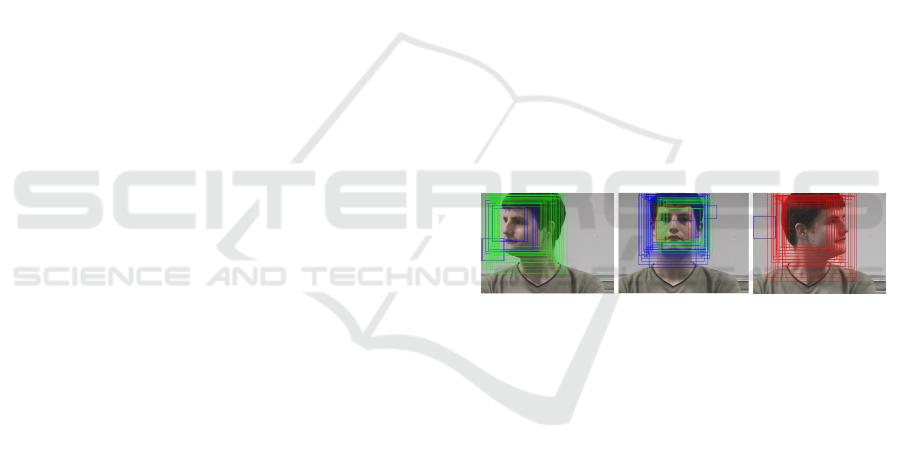
Figure 1: Image containing detected face candidates.
Green: output from left model, blue: output from frontal
model, red: output from right model.
hardware platform. An autonomous virtual camera-
man films actors independently of a human operator,
adjusting its position in order to comply with basic
cinematographic rules, such as the rule of thirds. This
rule signifies that a person looking to the right (this
is most likely where the action is taking place) should
be positioned on 1/3 on the left of the frame (and vice
versa) to leave some empty image space for the ac-
tion. To apply this rule we need to detect the face ori-
entation on the images taken by the UAV. Hereby the
UAV can steer itself to position the person left or right
in the frame depending on his face orientation like in
(Hulens et al., 2014) where a pan-tilt unit is used to
satisfy this rule. An even harder cinematographic rule
is that the virtual cameraman should maintain a cer-
tain shot for a longer time e.g. keeping a skier speed-
ing downhill in a profile close-up shot. This implies
that the exact angle of the face should be detected
so that the UAV can hold its position relatively to-
wards the face. Evidently, due to the hardware con-
538
Hulens, D., Beeck, K. and Goedemé, T.
Fast and Accurate Face Orientation Measurement in Low-resolution Images on Embedded Hardware.
DOI: 10.5220/0005716105380544
In Proceedings of the 11th Joint Conference on Computer Vision, Imaging and Computer Graphics Theory and Applications (VISIGRAPP 2016) - Volume 4: VISAPP, pages 538-544
ISBN: 978-989-758-175-5
Copyright
c
2016 by SCITEPRESS – Science and Technology Publications, Lda. All rights reserved

straints, our algorithm should be lightweight. For this,
we propose a methodology, based on only three de-
tection models, which are able to estimate the face
pan angle with excellent accuracy and real-time per-
formance whilst running on an embedded platform.
For validation, we employed both a publicly avail-
able dataset and composed our own database captured
from a UAV.
The remainder of this paper is structured as fol-
lows: In Section 2 we relate our method with the cur-
rent literature in head pose estimation. In Section 3
we explain how our approach works. Section 4 shows
our results and in Section 5 conclusions are drawn and
future work is discussed.
2 RELATED WORK
Head pose estimation is a vital component for numer-
ous applications like pedestrian safety (Schulz and
Stiefelhagen, 2012; Rehder et al., 2014; Yano et al.,
2014) where it is essential to know if the pedestrian
anticipated possible danger (looking towards it) or
for measuring car driver attentiveness (Paone et al.,
2015; Tawari et al., 2014; Oyini Mbouna et al., 2013)
to see if the driver is still alert. For those applications
several methods are developed the last few years that
are divided into two main categories: model-based
and appearance-based approaches.
In the first approach the location of facial features
(e.g. Haar features) combined with a geometrical face
model is used to determine the head pose. The latter
approach uses information of the entire facial region
and a separate detector is trained for different poses.
Examples of model-based approaches are (Pyun et al.,
2014; Shbib et al., 2014) where they first detect the
face and search for features that correspond to es-
sential points within that region (e.g. mouth, nose
and eyes). Depending on the spatial distribution of
those features a pose estimation is accomplished. An-
other model-based approach is presented in (Liew and
Yairi, 2015) where they overlay a 3D model of a hu-
man head with a 2D input image by connecting the fa-
cial features of the 2D images with features of the 3D
model. Using these methods on-board a UAV would
result in low accuracy, since it is difficult to find the
aforementioned facial features in these low resolution
images.
In appearance-based approaches generally a deci-
sion tree is learned where the leaves correspond with
a face at a certain angle. An example is (Benfold and
Reid, 2009), where they detect the gaze orientation of
people to infer interesting areas or events using ran-
domized ferns with decision branches based on both
histogram of oriented gradients (HOG) and color fea-
tures. In (Liu et al., 2014) and (Lu and Tan, 2013) a
manifold learning method is used to estimate the head
pose. They first extract features (e.g. intensity) from
a training set of head images and perform a manifold
analysis to learn a low-dimensional pose manifold
where after the low-dimensional features are used to
learn a multiple linear regression function. Prior tech-
niques work well in practice. However these methods
rely on an optimal head localization: if the localiza-
tion is not optimal (e.g. the bounding box is not cen-
tered exactly on the head) a large deviation in head
orientation occurs.
A totally different approach is to use 3D sensors
and depth-images to estimate the pose of a face. In
(Fanelli et al., 2011) they estimate the 3D coordi-
nate of the nose tip using random regression forests
trained on data captured from a range scanner while
in (Marks and Jones, 2015) triangular patch features
are extracted from the depth image of a persons’ head
and matched with a learned 3D model to estimate the
head pose. As cited in other work of (Fanelli et al.,
2012) the disadvantages of depth cameras are that the
most accurate ones work with structured infrared light
or time-of-flight which cannot be used outside. Other
cameras like stereo-setups do work outside but pro-
duce very noisy reconstructions. In addition, it is not
desirable to mount a stereo setup or depth sensor on
a UAV due to their weight and power consumption as
compared with a simple camera.
Our approach is also appearance-based but differs
significantly from previous methods since it uses only
three models (left-, right- and frontal-oriented) to es-
timate both the head pose and perform face detec-
tion simultaneously which accelerates the algorithm
tremendously. There is no need for training a compli-
cated decision tree and no time is spent on search-
ing for additional facial features. Furthermore we
use a simple light-weight webcam, to provide images,
which can easily be mounted on a UAV or other em-
bedded application.
3 APPROACH
The goal of our approach is to estimate the pan an-
gle of a face in a new image. To achieve this we use
three models of a face (−90
◦
, +90
◦
and 0
◦
) which
are trained using the Viola and Jones framework (Vi-
ola and Jones, 2001) (further referred as V&J). This
framework is a strong binary classifier constructed out
of several weak detectors. The weak detectors use
simple features (Haar features) to decide if a certain
image patch is part of the face or not. The detectors
Fast and Accurate Face Orientation Measurement in Low-resolution Images on Embedded Hardware
539
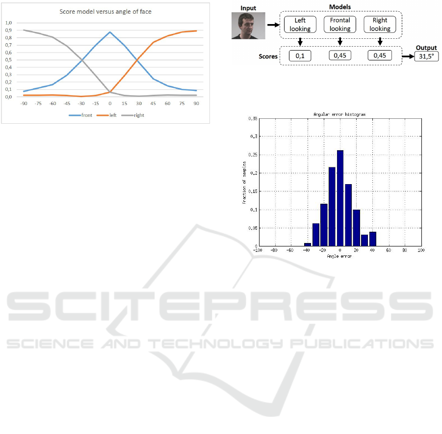
Figure 2: Relationship between the score of the model run-
ning over an image and the angle of the persons’ face in the
image. Orange: Left looking model, Blue: Frontal looking
model and Gray: Right looking model.
are placed in a cascade and if the image patch passes
through all of the cascade stages, it is classified as
positive. In our case only two models are trained (90
◦
and 0
◦
) and to evaluate −90
◦
the image is mirrored
and the 90
◦
model is used. For the sake of simplicity
we talk about three models.
For each new input image, each of these three
models thus returns a score indicating the probability
of that image patch containing a face at that specific
angle. The score they return is actually the number of
detections without employing non maxima suppres-
sion as seen in figure 1. When the face is e.g. look-
ing to the left, the left model will evidently output a
higher probability score than both the right and frontal
model.
We employed the face dataset of (Gourier et al.,
2004) to examine the relationship between the scores
of the V&J models and the angle of the person. The
face dataset contains 2790 monocular face images of
15 persons with variations of pan and tilt ranging from
−90
◦
to +90
◦
in steps of 15
◦
. We used 520 of the
780 images with a tilt angle of 0
◦
(260 images + 260
mirrored images) as training data. For each of these
thirteen angles we evaluated our three V&J models.
These scores are then normalized w.r.t. each other
such that their sum is 1. Because the scores are ac-
tually the number of detections they are normalized
to be independent of the image quality or light condi-
tions that can affect the number of detections. Figure
2 displays this normalized detection score for each of
these angles. As seen a clear relationship exist. We
propose two ways to exploit this to calculate the face
angle in an image. In the next section we first ex-
ploit a naive linear model approach, called baseline
approach. In section 3.2 we present our new more
accurate approach, coined Angle Model Approach.
Figure 3: Our three V&J models are validated on a new
input image and output a score for each model. An angle is
linear interpolated out of these scores.
Figure 4: Accuracy results Baseline.
3.1 Baseline Approach
Since the individual detection scores of the three mod-
els are normalized according to the method given
above and assuming to have a linear relationship be-
tween the detection score and the angle of the face,
we can derive the angle of a new input face image as
a simple weighted sum of the detection scores. This
is formulated as:
α = S
le ft
· (−90
◦
) + S
f ront
· (0
◦
) + S
right
· (90
◦
) (1)
Where α is the angle estimation of the new input face
image and S
le f t
, S
f ront
and S
right
are respectively the
score of the left, front and right model. The middle
term is added to the formula for the sake of clarity,
but is of course neglected due to the multiplication
with 0
◦
. Since the scores are normalized such that
∑
S
i
= 1, S
f ront
is not ignored but is incorporated in
S
le f t
and S
right
. An example of this approach is seen
in figure 3.
We evaluated this baseline approach on the
(Gourier et al., 2004) dataset. Figure 4 gives accuracy
results. When e.g. an error of ±15
◦
is allowed, 64%
of the samples are correctly classified with this sim-
ple approach. This approach runs at 13,34fps (frames
per second) (640 × 480 pixels) on a desktop computer
containing an Intel i7 processor and 20GB memory.
The input image can be much smaller (until the face is
undetectable), resulting in a significant acceleration.
VISAPP 2016 - International Conference on Computer Vision Theory and Applications
540
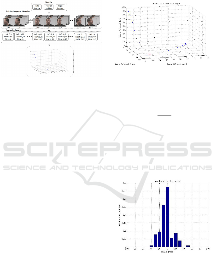
Figure 5: Overview of the training of the angle model.
3.2 Angle Model Approach
As we closely examine figure 2 the relationship be-
tween the model scores and the angles are not com-
pletely linear. Hence we propose that a model (the
Angle Model) of the scores for every of the 13 angles
(from −90
◦
to 90
◦
in steps of 15
◦
) is learned and the
scores of a new input image are compared with the
model.
3.2.1 Construction of the Angle Model
As previously mentioned, we ran our three V&J mod-
els over a set of images with 13 different angles.
The scores of every angle-set are normalized and dis-
played in figure 2. In order to make our angle model
we treated these normalized scores as a 3D point p
i
for every angle. Next each 3D point is plotted in a
3D map that forms the Angle Model. The workflow is
seen in figure 5.
As an example: the left most point in the map has
a left score of about 90% and a frontal and right score
of about 5%, this point corresponds evidently with a
face looking fully to the left or an angle of −90
◦
. This
angle model is trained on the desktop computer previ-
ously mentioned at a single core and took only 76 sec-
onds to learn a model from 520 images (we divided
the used dataset into a learning-part (520 images) and
a test-part (260 images)).
3.2.2 Detection and Angle Estimation
The estimation of the face-angle in a new image takes
place in a similar way as the training. For each new
input image a face is detected using the three V&J
models. Each model outputs a score and the three val-
ues are normalized and combined in a new 3D point
p
new
. This new point is plotted in our angle model as
in figure 6. To calculate the angle α corresponding to
Figure 6: Angle model in blue. New input p
new
in red.
p
new
the Euclidean distances d
1
and d
2
are calculated
between p
new
and the two nearest points p
1
and p
2
in our angle model that correspond with α
1
and α
2
.
Since d
1
and d
2
are known, α can easily be interpo-
lated with equation 2.
α = α
1
+
d
1
d
1
+ d
2
(α
2
− α
1
) (2)
The accuracy results are seen in figure 7. When
e.g. an error of ±15
◦
is allowed, 72% of the samples
are correctly classified. This approach runs at 13,4fps
on the previously described desktop which is about as
fast as the Baseline Approach but with a noticeably
better accuracy. If an error of only ±5
◦
is allowed,
we see an improvement of 12% more samples that is
correctly classified as compared to the Baseline Ap-
proach (38% vs. 26% correctly classified).
Figure 7: Accuracy results Angle Model.
4 EXPERIMENTS AND RESULTS
We conducted our experiments both on a publicly
available dataset (Gourier et al., 2004) with given
ground-truth and on our own dataset captured from
Fast and Accurate Face Orientation Measurement in Low-resolution Images on Embedded Hardware
541
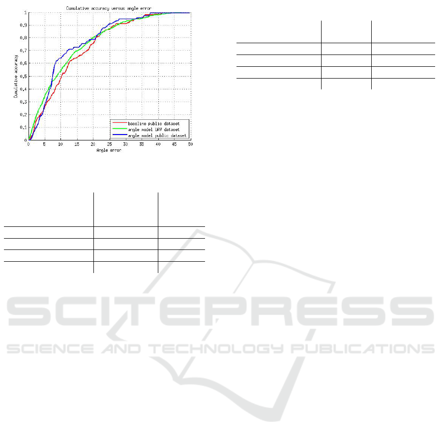
Figure 8: Accuracy results.
Table 1: Mean absolute error for both approaches.
Mean
Method range Absolute
Error
Benfold & Reid -180
◦
. . . 180
◦
37,9
◦
Rehder -180
◦
. . . 180
◦
19
◦
Ours-Baseline -90
◦
. . . 90
◦
13
◦
Ours-Model based -90
◦
. . . 90
◦
11,25
◦
a UAV where the compass of the UAV delivered the
ground-truth. Since we want to run our algorithm on-
board a UAV, experiments are performed on a desk-
top computer as well as on an embedded computer on
the UAV itself. One of the experiments we performed
was an accuracy measurement of both the baseline
approach and the angle model approach. Results can
be seen in figure 8. We can see a slightly better per-
formance of the angle model approach both on the
dataset and the images taken by the UAV.
Results of the angle model approach can be seen
in Figure 9.
Next the mean absolute error is calculated for both
approaches as can be seen in Table 1.
It is not trivial to compare our work with others
because of the use of non-publicly available datasets,
or a wider/smaller range of angles that can be de-
tected. In (Benfold and Reid, 2008) they use random-
ized ferns to estimate the head angle between −180
◦
and 180
◦
which yields in a mean absolute error of
37,9
◦
. In (Rehder et al., 2014) a logic regression clas-
sifier is trained for four different orientations together
with motion information from a KLT tracker. They
reach a mean absolute error of 19
◦
, which is still sig-
nificantly larger than ours and a lot more processing
power is needed, which is disadvantageous for em-
bedded applications like ours.
The next experiment we conducted was to observe
the effect of image downscaling on the angular error.
Downscaling the image yields an acceleration of the
Table 2: Speed results.
Baseline Angle Model
Approach Approach
Desktop avg. (fps) 13,34 13,4
Desktop max (fps) 73,17 73,48
Odroid avg. (fps) 2,33 2,35
Odroid max (fps) 12,49 12,39
algorithm but downscaling too much makes a face un-
detectable (too small for the V&J models). Figure 10
illustrates the relation between the height of a face
and the angular error of the algorithm. The optimal
face-height is 117 pixels. We can also observe that a
larger image does not yield a better angular error, this
is mainly due to more false detections. Moreover, also
for low resolution images with faces of only 75 pixels
high, our accuracy is still better than competition.
Next we conducted several speed experiments,
both on a normal desktop computer and on the pro-
cessing platform mounted on our UAV. Our UAV
is a Xbird 250 equipped with a Logitech webcam
(C310) and a processing board as seen in Figure 11.
The processing platform we utilize is an Odroid XU3
credit card sized minicomputer. It contains a Sam-
sung Exynos5422 Cortex-A15 2.0GHz quad core and
a Cortex-A7 quad core processor. We optimized the
algorithm to run at maximum speed specifically for
the Odroid board. In our images, the face height was
about 70% (350 pixels) of the image height (480 pix-
els). We downscaled the input image with scale factor
of 3 which was empirically determined as the most
optimal value according to our experiments above
(350 pixels / 117 pixels = 3). Most processing time
is spent on evaluating the V&J models, thus down-
scaling the image results in an acceleration. Both ap-
proaches are evaluated on a normal desktop computer
and on the Odroid at normal speed (input image is not
cropped (size = 640 × 480 pixels)) and at maximum
speed (image downscaled so that faces are still de-
tectable for our application (size = 213 × 160 pixels)).
As seen in Table 2 there is almost no difference in
processing speed between the baseline approach and
the Angle Model Approach. The image can be down-
scaled to 213 × 160 pixels without loss in accuracy.
We also made a demo towards our UAV appli-
cation where we used the calculated angle of a face
to control a pan-tilt unit with the camera mounted
on. The unit turns the camera to position the face
more left or right in the image depending on the
angle of the face, yielding cinematographically cor-
rect mid-shots. A movie of this demo can be seen
athttps://youtu.be/jprqiRlpap4.
VISAPP 2016 - International Conference on Computer Vision Theory and Applications
542
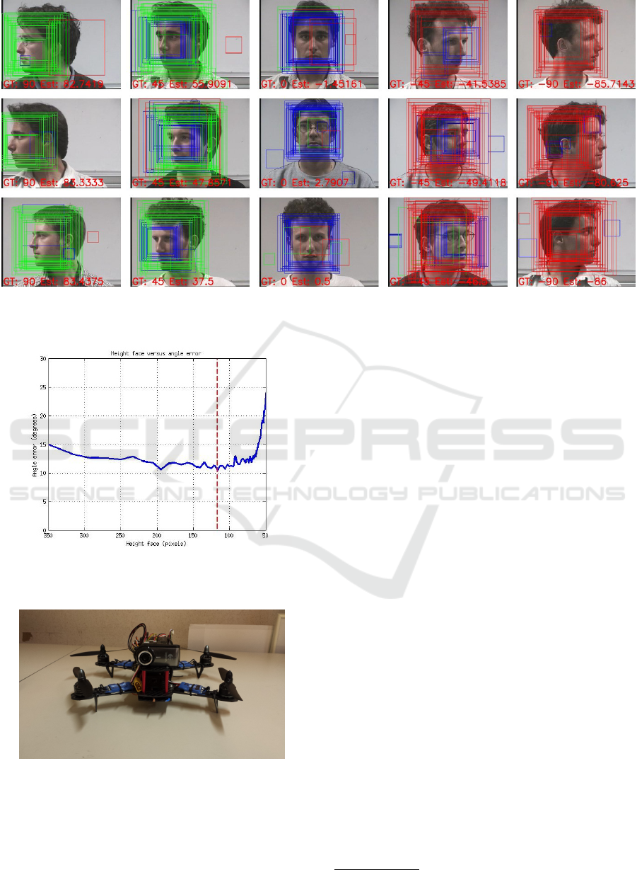
Figure 9: Result of the angle model approach on the dataset of (Gourier et al., 2004). In every image the ground truth angle
(GT) and the estimated angle (Est) is displayed. The color of the rectangle correspond with the model that is detected. Green:
Left looking model, Blue: Frontal looking model and Red: Right looking model.
Figure 10: Angular error versus face height. Optimal face
height = 117 pixels which corresponds with a rescale factor
of 3.
Figure 11: The UAV where we did our experiment with.
XBird 250 equipped with an Odroid XU3 processing board.
5 CONCLUSION AND FUTURE
WORK
In this paper we developed two approaches to cal-
culate the pan-angle of a face in an input image be-
tween −90
◦
and 90
◦
. We used the first approach as
a baseline and the second approach as an improve-
ment in accuracy without compromising on process-
ing speed. We validated these two approaches on
a publicly available dataset as well as on our own
recorded dataset from a UAV. The approaches are
also implemented on an Odroid embedded process-
ing platform attached on a UAV which prove that they
run in real-time on embedded hardware. Both meth-
ods have the advantage that they detect the face and
the angle with the same model, which is very ben-
eficial for processing speed. They are not using time
consuming decision-trees or facial landmarks but only
the relationship between learned angles and their cor-
responding scores and can work on images with rela-
tively low resolution. Because we made our code, an-
gle model and dataset publicly available
1
others can
implement and use our algorithm easily.
In the future we will integrate this angle estima-
tion technology in a virtual cameraman UAV demo,
choosing the right position for which to film an ac-
tor in order to get a requested shot. Furthermore, we
want to test our approaches using LBP features in-
stead of Haar features to train the previous models.
Using LBP features would increase the algorithms’
processing speed even further (integer calculations in-
stead of float calculations). As seen in Figure 9 false
detections occur. Filtering out these false detections
will yield in an even better accuracy.
1
www.eavise.be/hulens
Fast and Accurate Face Orientation Measurement in Low-resolution Images on Embedded Hardware
543

ACKNOWLEDGEMENTS
This work is supported by KU Leuven via the
CAMETRON project.
REFERENCES
Benfold, B. and Reid, I. (2008). Colour invariant head pose
classification in low resolution video. In BMVC, pages
1–10.
Benfold, B. and Reid, I. (2009). Guiding visual surveillance
by tracking human attention. In BMVC, pages 1–11.
Fanelli, G., Gall, J., and Van Gool, L. (2011). Real time
head pose estimation with random regression forests.
In Computer Vision and Pattern Recognition (CVPR),
2011 IEEE Conference on, pages 617–624. IEEE.
Fanelli, G., Gall, J., and Van Gool, L. (2012). Real time 3d
head pose estimation: Recent achievements and future
challenges. In Communications Control and Signal
Processing (ISCCSP), 2012 5th International Sympo-
sium on, pages 1–4. IEEE.
Gourier, N., Hall, D., and Crowley, J. L. (2004). Estimat-
ing face orientation from robust detection of salient
facial structures. In FG Net Workshop on Visual Ob-
servation of Deictic Gestures, pages 1–9. FGnet (IST–
2000–26434) Cambridge, UK.
Hulens, D., Goedem
´
e, T., and Rumes, T. (2014). Au-
tonomous lecture recording with a ptz camera while
complying with cinematographic rules. In Computer
and Robot Vision (CRV), 2014 Canadian Conference
on, pages 371–377. IEEE.
Liew, C. F. and Yairi, T. (2015). Human head pose esti-
mation and its application in unmanned aerial vehicle
control. In The Malaysia-Japan Model on Technology
Partnership, pages 327–336. Springer.
Liu, Y., Wang, Q., Jiang, Y., and Lei, Y. (2014). Supervised
locality discriminant manifold learning for head pose
estimation. Knowledge-Based Systems, 66:126–135.
Lu, J. and Tan, Y.-P. (2013). Ordinary preserving mani-
fold analysis for human age and head pose estima-
tion. Human-Machine Systems, IEEE Transactions
on, 43(2):249–258.
Marks, T. and Jones, M. (2015). Real-time head pose es-
timation and facial feature localization using a depth
sensor and triangular surface patch features.
Oyini Mbouna, R., Kong, S. G., and Chun, M.-G. (2013).
Visual analysis of eye state and head pose for driver
alertness monitoring. Intelligent Transportation Sys-
tems, IEEE Transactions on, 14(3):1462–1469.
Paone, J., Bolme, D., Ferrell, R., Aykac, D., and Karnowski,
T. (2015). Baseline face detection, head pose estima-
tion, and coarse direction detection for facial data in
the shrp2 naturalistic driving study. In Intelligent Ve-
hicles Symposium (IV), 2015 IEEE, pages 174–179.
IEEE.
Pyun, N.-J., Sayah, H., and Vincent, N. (2014). Adaptive
haar-like features for head pose estimation. In Image
Analysis and Recognition, pages 94–101. Springer.
Rehder, E., Kloeden, H., and Stiller, C. (2014). Head detec-
tion and orientation estimation for pedestrian safety.
In Intelligent Transportation Systems (ITSC), 2014
IEEE 17th International Conference on, pages 2292–
2297. IEEE.
Schulz, A. and Stiefelhagen, R. (2012). Video-based pedes-
trian head pose estimation for risk assessment. In In-
telligent Transportation Systems (ITSC), 2012 15th In-
ternational IEEE Conference on, pages 1771–1776.
IEEE.
Shbib, R., Zhou, S., Ndzi, D., and Alkadhimi, K. (2014).
Head pose estimation for car drivers. International
Journal of u-and e-Service, Science and Technology,
7(4):359–374.
Tawari, A., Martin, S., and Trivedi, M. M. (2014). Contin-
uous head movement estimator for driver assistance:
Issues, algorithms, and on-road evaluations. Intelli-
gent Transportation Systems, IEEE Transactions on,
15(2):818–830.
Viola, P. and Jones, M. (2001). Rapid object detection using
a boosted cascade of simple features. In Computer Vi-
sion and Pattern Recognition, 2001. CVPR 2001. Pro-
ceedings of the 2001 IEEE Computer Society Confer-
ence on, volume 1, pages I–511. IEEE.
Yano, S., Gu, Y., and Kamijo, S. (2014). Estimation of
pedestrian pose and orientation using on-board cam-
era with histograms of oriented gradients features. In-
ternational Journal of Intelligent Transportation Sys-
tems Research, pages 1–10.
VISAPP 2016 - International Conference on Computer Vision Theory and Applications
544
