
Towards an Agent-driven Software Architecture Aligned with User
Stories
Yves Wautelet
1
, Samedi Heng
2
, Manuel Kolp
2
and Christelle Scharff
3
1
Faculty of Economics and Business, KULeuven, Brussels, Belgium
2
Louvain School of Management, Universit
´
e Catholique de Louvain, Louvain-La-Neuve, Belgium
3
Seidenberg School of Computer Science and Information Systems, Pace University, New York, U.S.A.
Keywords:
Agent Architecture, Agile Development, User Story, Agile Architecture, Multi-agent System.
Abstract:
Agile principles have taken an increasing importance in the last decades. Software Architecture (SA) definition
is perceived as a non-agile practice as it is executed in a top-down manner, reminding waterfall development,
and sometimes imposes heavy documentation. This paper proposes to systematically build an agent-oriented
SA from a set of User Stories (US), the core artifact to document requirements in agile methodologies. Pre-
vious research has allowed to define a unified US meta-model for the generation of templates relating WHO,
WHAT and WHY elements. This meta-model’s elements define a syntax issued from practitioners templates
associated with semantics from Goal Oriented Requirements Engineering frameworks, more precisely i*. With
a set of US following the templates of this previous model, the link between the US and SA concepts is sys-
tematically studied and a transformation process is proposed. The SA can decline agent behaviors aligned
with requirements and organizational behaviors. Moreover, requirements (thus US) are subject to evolution
through agile iterations; the SA can evolve with these changes in a semi-automatic manner. We thus argue that
the Agent-SA produced with our transformation process contributes to the overall project agility.
1 INTRODUCTION
(Abrahamsson et al., 2010) highlights the core oppo-
sition between Software Architecture (SA) definition
within a software project – seen as a top-down prac-
tice implying heavy documentation – and agile devel-
opment. The Agile Manifesto emphasizes four values
in agile development: (i) Individuals and interactions
over processes and tools; (ii) Working software over
comprehensive documentation; (iii) Customer collab-
oration over contract negotiation; and (iv) Respond-
ing to change over following a plan. Agile principles
seem thus opposed to SA design unless the SA can
evolve together and parallel to the requirements. Such
an evolution would be eased if the SA would follow
agile-style requirements definition. In agile method-
ologies, requirements are expressed using User Sto-
ries (US). US are written in natural language by the
customer and they describe user functionalities at an
abstract level.
In this work, we consequently suggest to system-
atically derive part of the SA from the set of US of a
project in the form of a multi-agent architecture better
aligned with agile principles. At the end, we want to
dispose of a SA definition that is not heavy but can
be partly automated and changed with the evolution
of the US models, only if they are properly struc-
tured following the model defined in (Wautelet et al.,
2014). This model’s elements define a syntax issued
from practitioners templates associated with seman-
tics from Goal Oriented Requirements Engineering
(GORE) frameworks, more precisely i* (Yu et al.,
2011). The implementation of the agent-architecture
is outside the scope of this paper, but an implementa-
tion model in line with the SA can be found in (Kiv
et al., 2012).
2 STRUCTURING USER STORY
CONCEPTS
This section exposes the “building blocks” used
within this research.
2.1 Macro-level: Ways to Organize User
Stories
We first distinguish a US macro-level dealing with the
Wautelet, Y., Heng, S., Kolp, M. and Scharff, C.
Towards an Agent-driven Software Architecture Aligned with User Stories.
DOI: 10.5220/0005706103370345
In Proceedings of the 8th International Conference on Agents and Artificial Intelligence (ICAART 2016) - Volume 2, pages 337-345
ISBN: 978-989-758-172-4
Copyright
c
2016 by SCITEPRESS – Science and Technology Publications, Lda. All rights reserved
337

grouping of US into depending (i.e. relating) sets. We
thus consider here the US as potential building blocks
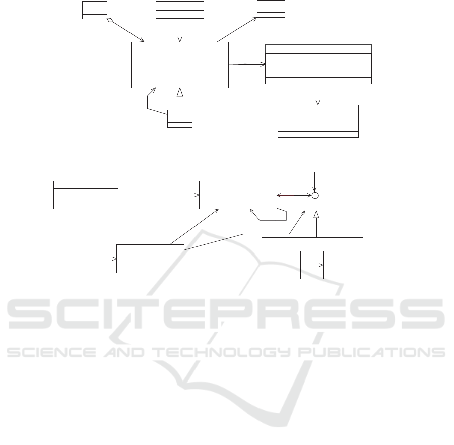
serving for SA composition/decomposition. Figure 1
presents our meta-model of the US concepts.
AcceptanceTest
Feature
Theme
Epic
User_Story
priority : Integer
amountOfPoints : Integer
status : ENUM{0_US,IP_US,C_US}
conversation : Text
1
1..n
1
1..n
Fulfills
1..n1..n
Requires
n
groups
1..n
0..1
1..n
0..1
is refined in
0..n0..n
Figure 1: US as Macro-Level Structures: Meta-Model.
The User Story class represents the US as a
whole. US are written by the customer or product
owner at the earliest stages of the project and put in
the product backlog with a (implementation) priority
and an amountOfPoints which refers to the number of
User Story Points (USP)
1
(Cohn, 2004; Leffingwell,
2010). As a result, these elements have been added
as attributes to the User Story class. Additional at-
tributes required for process management are also in-
cluded within the User Story class.
The concept of US is by essence granular in the
sense that some US need to be refined into other ones
since they are too abstract to be estimated, imple-
mented and tested in their initial forms. These US
are called Epics (Cohn, 2004). Epics are US with a
high level of abstraction meaning that they must be
refined/decomposed into smaller US to fully describe
the requirement they refer to. These US are repre-
sented by the class Epic that inherits from the US
class. As we will see later on, Epic US contain coarse-
grained process elements that cannot be transformed
at once in the SA (see Section 4.2).
Other concepts evoked in the meta-model of Fig-
ure 1 are non-relevant for the present research and will
not be discussed.
2.2 Micro-level: Decomposing a User
Story in Descriptive Concepts
Within Figure 2, the meta-model of the previous sec-
tion is enriched with the constituting elements of the
US. We refer to this US view as the micro-level.
Rather than using the US as a whole within the
requirements analysis process, we suggest, in our re-
search design, to decompose the US on the basis of
1
The amount of USP represents the estimated effort re-
quired to implement the US.
their WHO, WHAT and, when available, WHY dimen-
sions. To ensure uniformity, these elements are all
characterized as Descriptive Concepts (D C). When
decomposed into a set of D C, the dependency be-
tween D C is intended to be further studied (see Sec-
tion 2.3). Each element of a US template relating to
one of the 3 dimensions is then an instance of the D C
class. For the template of a US: As a <role>, I need
a <task> so that <goal>, we have 3 instances of
the D C class: one for role, one for task and one for
goal. The dimension attribute thus compulsorily takes
one of the values WHO (for role), WHAT (for task) or
WHY (for goal) and the syntax attribute takes the syn-
tax of the concept name (role, task, goal, ...). The
semantic attribute relates to the definition of the D C.
The list of all the possible D C is given in the form
of a meta-model allowing to define US templates in
Section 2.3.
Finally, since different D C can be linked together,
we introduce the Link class that represents the possi-
ble types of links between two D C. Typically such
links can be (at least partially) found in a logical way
through agents’ behavior at the level of the SA (see
Section 6).
2.3 Unified-model of User Stories’
Descriptive Concepts
(Wautelet et al., 2014) proposes to build a unified
model for designing US templates. The interested
reader will refer to the latter reference for research
and process related details. Figure 3 represents the
meta-model of US templates. A US template can be
designed from taking an element of the WHO, WHAT
and possibly WHY dimensions. The link between the
classes conceptually represents the link from one di-
mension to the other. Specifically, the unidirectional
association from the Role to one of the Capability,
Task or Goal classes implies that the target class in-
stantiates an element of the WHAT dimension (al-
ways tagged as wants/wants to/needs/can/would like
in the model). Then, the unidirectional association
from one of these classes instantiating the WHAT di-
mension to one of the classes instantiating the WHY
dimension (always tagged as so that into the model)
implies that the target class eventually (since 0 is the
minimal cardinality) instantiates an element of the
WHY dimension. A US template supported by our
model is for instance: As a <role>, I would like
<task> so that <hard-goal>.
Each concept is associated with a particular syn-
tax (identical to the name of the class in Figure 3) and
a semantic. The syntax and semantics of the model
are summarized here. As a result of the research
ICAART 2016 - 8th International Conference on Agents and Artificial Intelligence
338
Link
type : String
sibling : Descriptive_Concept
AcceptanceTest
Feature
Theme
Epic
Descriptive_Concept
dimension : ENUM{WHO,WHAT,WHY}
syntax : String
semantic : String
0..n
1
0..n
1
User_Story
priority : Integer
amountOfPoints : Integer
status : ENUM{0_US,IP_US,C_US}
conversation : Text
1
1..n
1
1..n
Fulfills
1..n1..n
Requires
n
groups
1..n
0..1
1..n
0..1
is refined in
2..31..n 2..31..n
includes
0..n0..n
Figure 2: US as Macro and Micro-Level Structures: Meta-Model.
Soft_Goal
dimension : Enum{WHAT,WHY}
name : String
Hard_Goal
dimension : Enum{WHAT,WHY}
name : String
0..n
0..n
0..n
0..n
so that
Capability
name : String
dimension : String = WHAT
Role
name : String
dimension : String = WHO
0..n
1..n
0..n
1..n
wants/wants to/needs/can/would like
Task
name : String
dimension : Enum{WHAT,WHY}
0..n1..n 0..n1..n
wants/wants to/needs/can/would like
0..n
0..n
0..n
0..n
so that
0..n
0..n
0..n
so that
0..n
Goal
0..n
0..n
0..n
0..n
so that
0..n
1..n
0..n
1..n
wants/wants to/needs/can/would like
0..n
0..n
0..n
0..n
so that
Figure 3: Unified Model for User Story Descriptive Concepts.
conducted in (Wautelet et al., 2014), all these cou-
ples syntax/semantic are issued of (Yu et al., 2011).
Specifically:
• A Role is an abstract characterization of the be-
havior of a social actor within some specialized
context or domain of endeavor;
• A Task specifies a particular way of attaining a
goal;
• A Capability represents the ability of an actor to
define, choose, and execute a plan for the fulfill-
ment of a goal, given certain world conditions and
in the presence of a specific event;
• A Hard-goal is a condition or state of affairs in the
world that the stakeholders would like to achieve;
• A Soft-goal is a condition or state of affairs in the
world that the actor would like to achieve. But
unlike a hard-goal, there are no clear-cut crite-
ria for whether the condition is achieved, and it
is up to the developer to judge whether a particu-
lar state of affairs in fact achieves sufficiently the
stated soft-goal.
More explanations for distinguishing Hard-goal,
Task and Capability elements will be discussed in
Section 4.
3 A STRUCTURE FOR DEFINING
THE SOFTWARE
ARCHITECTURE
This section exposes the main building blocks of the
abstract agent-architecture that will be used to map
US concepts in order to automatically align part of
the SA with the collected requirements. Examples of
each of the elements are provided in the illustrative
example of Section 6.
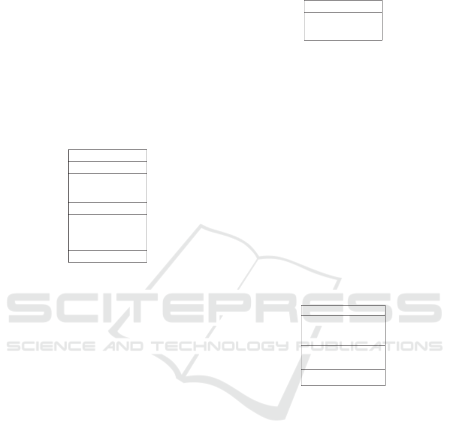
3.1 Agent Structure
Figure 4 proposes a generic template for the Agent
concept. The definition of an Agent is composed of
five parts: Attributes, Events, Plans, Beliefs and Meth-
ods.
We typically refer in this work to BDI agent im-
plementation platforms such as JADE, JACK Intelli-
gent Agents or the Jadex BDI Agent System (Pokahr
et al., 2005; Pokahr et al., 2013; Pokahr et al., 2014).
The agent class allows to specify:
• the declaration of agent attributes;
• the events (both internal and external) that the
agent (i) handles, (ii) can post internally (to be
Towards an Agent-driven Software Architecture Aligned with User Stories
339
handled by other plans), or (iii) can send exter-
nally to other agents;
• the plans that the agent can execute;
• the beliefs the agent can use and refer to. The be-
liefs of an agent can be of type private, protected,
or public. A private access is restricted to the
agent to which the belief belongs. Protected ac-
cess is shared with other agents of the same class,
while public access is unrestricted;
• the declaration of agent methods (e.g., the con-
structor of an agent).
Agent
Attribute
Event
Plan
Belief
Method
<plan>
<belief>
<belief>
<belief>
private belief
post
send <event>
<event>
protected belief
public belief
Figure 4: Agent template.
3.2 Event Structure
Events describe stimuli, emitted by agents or auto-
matically generated, in response to which other or the
same agents must take action.
Events are the origin of all activity within an
agent-oriented system. In the absence of events an
agent stays idle. Whenever an event occurs, an agent
initiates a task to handle it. This task can be thought
of as a thread of activity within the agent. The task
causes the agent to choose between the plans it has
available, executing a plan or a set of plans until it
succeeds or fails.
There are different event types, each with different
uses. Events can be described along three dimensions:
• External or internal event: external events are sent
to other agents while internal events are posted by
an agent to itself;
• Normal or BDI event: an agent has a number of al-
ternative plans to respond to a BDI event and only
one plan in response to a normal event. Whenever
an event occurs, the agent initiates a plan to handle
it. If the plan execution fails and if the event is a
normal event, then the event is said to have failed.
If the event is a BDI event, a set of plans can be
selected for execution and these are attempted in
turn. If all selected plans fail, the event is also said
to have failed;
Belief
Attribute
key
value
FieldType FieldNam
e
FieldType FieldNam
e
Figure 5: Belief template.
• Automatic or nonautomatic event: an automatic
event is automatically created when certain belief
states arise.
3.3 Belief Structure
A Belief describes a piece of knowledge that an agent
has about itself and its environment.
Figure 5 shows a template of a belief. Every be-
lief that an agent currently has is represented as tu-
ples. It has key and value fields. The key FieldType
Fieldname declaration describes the key attributes,
while the value FieldType FieldName declaration
describes the data attributes of each belief. A belief
may have zero or more key or value field declarations.
3.4 Plan Structure
A plan describes a sequence of actions that an agent
can take when an event occurs.
Plan
Event
Used Belief
Method
<event>
<event>
<event>
<belief>
<belief>
handle
post
send
read
modify
main() {}
Figure 6: Plan template.
Plans are structured in three parts as shown in Fig-
ure 6: the Event part, the Belief part, and the Method
part. The Event part declares events that the plan han-
dles (i.e., events that trigger the execution of the plan)
and events that the plan produces. The latter can be
either posted (i.e., sent by an agent only to itself) or
sent (i.e., sent to other agents). The Belief part de-
clares beliefs that the plan reads and those it modifies.
The Method part describes the plan itself, that is, the
actions performed when the plan is executed. In the
following, we study in more detail each part of the
plan template.
3.4.1 Events in Plans
handle <event>
Whenever an agent detects that an event arises, it tries
to find a plan to handle the event.
ICAART 2016 - 8th International Conference on Agents and Artificial Intelligence
340

The event the agent can handle is identified by its
plans’ handle <event> declarations. When an in-
stance of a given event arises, the agent may execute
one of the plans that can handle this event.
The handle <event> declaration is mandatory.
Whenever an instance of this event occurs, the agent
will consider this plan as a candidate response. With-
out a handle <event> declaration, a plan would
never be executed by an agent.
post <event>
The post <event> statement declares that the
plan is able to post this event when executed. This
may be in one of the methods declared in the Method
part. Only events that the agent posts internally are
declared after the post statement.
send <event>
The send <event> declaration is similar to the
post <event> declaration, except that it identifies
events that the plan can send to other agents. A plan
is able to send an event through one of the methods
declared in the Method part.
3.4.2 Used Beliefs in Plans
read <belief>
The read <belief> declaration indicates that the
<belief> is to be read (and only read) within the
plan.
modify <belief>
The modify <belief> statement indicates that
the <belief> may be read and modified within the
plan.
3.4.3 Methods in Plans
All the plan’s methods are declared in the method
part. Two of these methods are worth to be pointed
out: context() and main().
An agent may further discriminate plans that han-
dle an event by determining whether a plan is rele-
vant. The context() method allows the agent to de-
termine which plan to execute when a given event oc-
curs. To be relevant, the plan must declare that it is
capable of handling the event that has arisen (via the
handle <event> declaration) and that it is relevant
to the event instance (via the context() method).
context() is a boolean method. If this method
returns true, the plan is relevant to the event. If not,
the plan is not relevant to the event.
The main() method is executed whenever a plan
is executed. The main() method is just like the
main() method in Java – it represents the starting
point in a plan’s execution.
4 BRIDGING A SET OF US TO A
MULTI-AGENT SOFTWARE
ARCHITECTURE
The aim of this Section is, starting from the De-
scriptive Concepts defined into the model presented
in Section 2.3, to study the transformation possibili-
ties to the element constituting the agent SA.
4.1 Role
A Role within a US is transformed in an intentional
Agent in the SA. This way, an organizational role
(which is most often a software user) is literally
mapped to an intelligent acting entity at run-time into
the system.
4.2 Hard-goal
The Hard-goal is the most abstract element since it is
a condition or state of affairs that must be attained but
there is no defined way to attain it or more precisely
several ways could be followed in practice contrarily
to the task that represents an operational way to attain
a Hard-goal. An example of a Hard-goal could, for
example, be to Graduate for a diploma in Business In-
formation Management; it can be the Hard-goal of a
student but there are several ways to attain this Hard-
goal .
Being highly abstract, Hard-goals are not right
away transformed into a functional aspect in the soft-
ware architecture. US containing Hard-goals can be
(but not necessarily) Epic US. Their satisfaction is
rather supported by one or several Task(s) and/or Ca-
pabilities that will themselves be transformed into the
agent architecture (see Section 4.3).
4.3 Task & Capability
The Task and the Capability represent more concrete
and operational elements but these two need to be dis-
tinguished. The Capability could in fact be modeled
as a Task but the Capability has more properties than
the former since it is expressed as a direct intention
from a role. In order to avoid ambiguities in interpre-
tation, we use of the Capability element only for an
atomic Task (i.e., a task that is not refined into other
Towards an Agent-driven Software Architecture Aligned with User Stories
341

Elements
Plan
Belief
Structural Diagram
Communication
Diagram
Multi
-Agent System Design
Event
Soft_Goal
Dynamic Diagram
Role Capability
Hard_Goal
Task
+
+
realizes executes
Agent
Figure 7: The Forward Engineering Process.
elements but is located at the lowest level of hierar-
chy). A Task could then be Take the Business Intel-
ligence Methods class and a Capability would be Fill
in the Exam.
The Task representing a whole process composi-
tion will be transformed as a Plan, while Capability,
by nature atomic, will be transformed in an Event.
4.4 Soft-goals
Soft-goals are not transformed at operational level but
other Hard-goals and Tasks contribute positively or
negatively to their satisfaction. These latter Hard-
goals and Tasks are themselves transformed into the
agent architecture as evoked above.
5 SOFTWARE
TRANSFORMATION PROCESS
Figure 7 graphically illustrates the transformation
process defined in the previous section. With respect
to the SA:
• A Role element is transformed into an Agent;
• A Task element is transformed into a Plan;
• A Capability element is transformed into an
Event.
Let us also note that Domain Entities (DE) ma-
nipulated by the Agents to fulfill the elements evoked
above will form the Beliefs in the SA. DE are not ex-
pressed as such in US but rather physical or logical
resources manipulated by Roles in the realization of
US. This means they are derived from a careful read-
ing of the US.
On the bottom right side of Figure 7, we can also
note three types of diagrams – the Structural Diagram
(SD), the Communication Diagram (CD) and the Dy-
namic Diagram (DD) – representing complementary
views of the agents properties and behavior at system
level. Due to a lack of space and with the willingness
to focus on the transformation process only, we will,
in the context of this paper, focus on the SD only.
6 ILLUSTRATIVE EXAMPLE
This section exposes the illustrative example on
which we apply the SA transformation process. Note
that this illustrative example is taken from a bigger
case but that, due to a lack of space, the set of US
chosen and their transformation into the SA is lim-
ited.
6.1 User Stories
Our proposal will be illustrated using a running ex-
ample about carpooling. Carpooling deals with shar-
ing car journeys so that more than one person trav-
els within a car. In this context, it becomes increas-
ingly important to save gas, reduce traffic, save driv-
ing time and control pollution. ClubCar is a multi-
channel application available as an Android applica-
tion, SMS service and IVR system. Users of Club-
Car are riders and/or drivers that can register by SMS,
voice or through an Android app. Roughly speaking,
the software allows drivers to propose rides and sub-
mit their details with dates, times, sources and des-
tinations while riders can search for available rides
(Shergill and Scharff, 2012).
As shown in Table 1, we have taken a sample of
the US of the ClubCar application to illustrate the re-
search developed in this paper. The first column de-
picts the Dimension of US D C, the second column
describes the element itself and the last column gives
the type of the D C
2
.
2
Note that, when there were several possibilities, an
ad-hoc choice has been made since envisaging the multi-
ple modeling solutions at the level of the unified template
model is not the focus of the present research.
ICAART 2016 - 8th International Conference on Agents and Artificial Intelligence
342
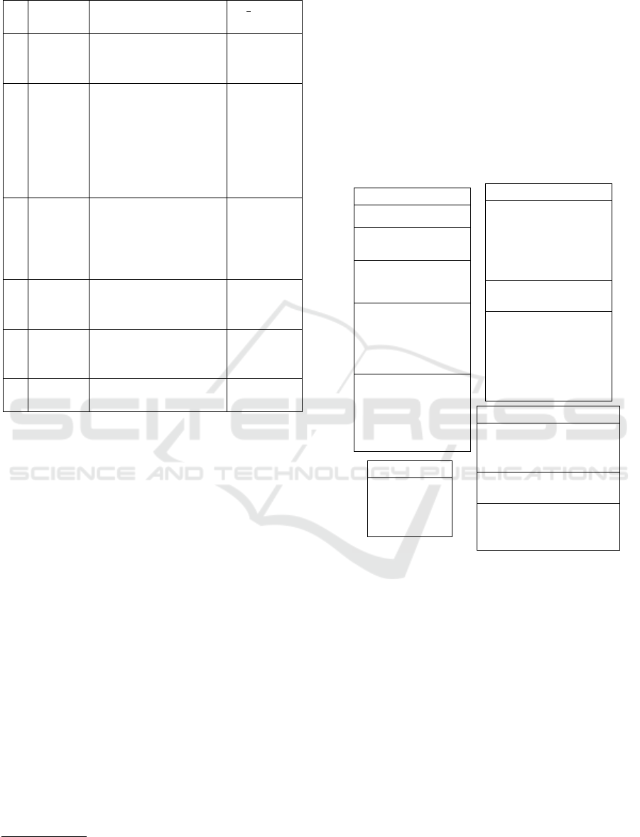
Table 1: US sample issued of the ClubCar development.
# Dimen-
sion
Element D C Type
1 WHO As a DRIVER Role
WHAT I want to propose
rides to Riders
Hard-goal
2 WHO As a DRIVER Role
WHAT I want to propose
a ride from A to B
with the price loca-
tion and time of de-
parture, and number
of seats available
Task
3 WHO As a DRIVER Role
WHAT I want to log in to the
platform
Capability
WHY so that I can register
to the service
Task
4 WHO As a DRIVER Role
WHAT I want to select the
ride characteristics
Capability
5 WHO As a DRIVER Role
WHAT I want to confirm the
proposal
Capability
6 WHO As a RIDER Role
WHAT I want to order a ride Capability
6.2 Agent Architecture
US1 contains a Hard-goal element in the WHAT di-
mension and constitutes an Epic US so that it is not
forwarded as such to the SA but is satisfied through
the realization of the Task element in US2. Never-
theless we can “manually” identify the presence of a
DE which is the Ride that will be transformed into a
Belief (see hereunder).
As illustrated in Figure 8, the ProposeRideFro-
mAtoB Plan is forwarded from the Task element de-
picted in US2. It is used by the Driver Agent to pro-
pose a ride to the Rider Agent
3
. The Plan is executed
when the CharacteristicsSelected Event (con-
taining the information about the characteristics of the
Ride offered by the Driver) occurs. The latter Event
is forwarded from US4. The ProposeRideFromA-
toB Plan also creates a Ride Belief, i.e. the Driver
belief storing the proposed Ride that can then be pro-
posed to a Rider Agent. Later, the Rider Agent can
subscribe for the proposed Ride.
DriverProposalConfirmation is an Event trans-
formed from US5 that is posted automatically when-
ever the value of the status field (of the Ride Belief)
3
Due to a lack of space the Rider Agent has not been
represented in Figure 8.
is set to submitted. It will then invoke a plan to inform
the Rider that the Ride is available.
The RiderOrder Event (not illustrated in Figure
8) belonging to the Rider Agent is sent when the
Rider Agent subscribed to a Ride offered by the
Driver Agent. This Event is transformed from the
Capability element in US6.
As evoked in the previous section, other agent be-
havior is outside the scope of the this paper that fo-
cuses on systematic forward engineering of US to a
SA, therefore the full SD as well as CD and DD are
not represented here.
<<Plan>> ProposeRideFromAtoB
Event
handle
LogIn
CharacteristicsSelected
post
RideCharacteristicsRecorded
send
DriverProposalConfirmation
Used Beleif
modify
Ride
Method
main()
{
// save ride proposition to
// Driver’s belief
// post and send events upon
// the Ride availability and
// characteristics
}
<<Agent>> Driver
Attribute
String Name
Event
InformRideDone
……..
Plan
ProposeRideFromAtoB
……..
Beleif
private beleif
Ride
……..
public belief
RideCharacteristics
Method
// Constructor
public Driver (Dname)
// load data to the beliefs
// of the driver
public void loadBK_Driver()
…………..
<<Event>> DriverProposalConfirmation
Attribute
Scope: <<Internal>>
Type : <<Normal>>
// String rCode
// String DriverID
Creating Method
// createEvnt (String rRCode,
// String DriverID)
Created Automatically
create when
driver.confirm(Ride)
use beleif
Ride
<<Beleif>> Ride
Attribute
key
// String rCode
// String DriverID
value
// Enum Status
Figure 8: Structural Diagram – ClubCar Example.
7 RELATED WORK
Agile development and SA have been identified as the
fourth position among the top ten research questions
that should be addressed by the community (Freuden-
berg and Sharp, 2010). The actual researches on this
area are focused on quantity of SA rather than quality
(Babar et al., 2013). SA is seen as a human activ-
ity based on designers experience meaning that most
architectures are ad-hoc and only some follow a de-
fined pattern (Booch, 2008). Many practitioners have
argued that model-driven engineering as well as user-
center design are beneficial for constructing a SA in
the agile environment (Babar et al., 2013). We point
to the development of a SA not following patterns but
aligned on the structure of requirements.
Towards an Agent-driven Software Architecture Aligned with User Stories
343

To the best of our knowledge, there is no work
on mapping the US to agent SA. In most existing re-
search, US are generated and decomposed from the
SA elements. (Leffingwell, 2010) proposes the scaled
agile framework that emphasizes on the importance of
building the SA to support development. They how-
ever do not furnish any mechanism for building and
and tracing the SA. (Perez et al., 2014) propose a sim-
ilar framework that bridges US to SA elements; US
are nevertheless considered as fine-grained elements
only.
We can also focus on the use of US in agent meth-
ods. In Agile PASSI (Chella et al., 2006), US are used
as requirement artifact for communication but its their
only usage. US, specifically in MaSE (DeLoach et al.,
2002), is one source of requirements for capturing
the goal of the agent (Wood and DeLoach, 2001) but
without formal transformation. (Gaur and Soni, 2012)
use fuzzy theory to provide a systematic and method-
ical approach to explore various dependencies such as
goal, task, resource or soft-goal from US. Again the
technique is limited at analysis stage with no transfor-
mation. In contrast, (Tenso and Taveter, 2013) adopt
agent-oriented modeling in agile development. They
provide a method for decomposing a goal into sub-
goals and link them to US elements. (Carrera et al.,
2014) use US as testing mechanism for agent-oriented
software development. Only one US template is used
and aligned to JBehave (http://jbehave.org).
8 CONCLUSION
The quest for agility has, in the recent years, been
conducted in several domains and, behind the buzz
word, companies are looking for a high-level of align-
ment between user requirements and software as well
as rapid respond to change. This paper has proposed
to map US – THE requirements models of agile soft-
ware development methods like SCRUM and XP –
with an agent-based SA in order to implement a soft-
ware system made of Agents mapping organizational
behavior at run-time. The transformation process can
be partially automated for rapid response to change
and to avoid a heavy documentation process.
Future work includes a full validation on the
ideas on a broader case study. A plug-in support-
ing the automatic transformation of US elements into
the proposed SA is under development within the
DesCARTES Architect CASE Tool.
REFERENCES
Abrahamsson, P., Babar, M. A., and Kruchten, P. (2010).
Agility and architecture: Can they coexist? IEEE
Software, 27(2):16–22.
Babar, M. A., Brown, A. W., and Mistrik, I. (2013). Agile
Software Architecture: Aligning Agile Processes and
Software Architectures. Morgan Kaufmann Publ.
Booch, G. (2008). Architectural organizational patterns.
Software, IEEE, 25(3):18–19.
Carrera,
´
A., Iglesias, C. A., and Garijo, M. (2014).
Beast methodology: An agile testing methodology for
multi-agent systems based on behaviour driven devel-
opment. Info. Syst. Frontiers, 16(2):169–182.
Chella, A., Cossentino, M., Sabatucci, L., and Seidita, V.
(2006). Agile passi: An agile process for designing
agents. International Journal of Computer Systems
Science & Engineering, 21(2):133–144.
Cohn, M. (2004). User Stories Applied: For Agile Software
Development. Addison Wesley.
DeLoach, S. A., Matson, E. T., and Li, Y. (2002). Apply-
ing agent oriented software engineering to cooperative
robotics. In FLAIRS Conference, pages 391–396.
Freudenberg, S. and Sharp, H. (2010). The top 10 burning
research questions from practitioners. IEEE Software,
27(5):8–9.
Gaur, V. and Soni, A. (2012). A novel approach to explore
inter agent dependencies from user requirements. Pro-
cedia Technology, 1:412–419.
Kiv, S., Wautelet, Y., and Kolp, M. (2012). Agent-driven
integration architecture for component-based software
dvpt. Trans. Comp. Collect. Intell., 8:121–147.
Leffingwell, D. (2010). Agile software requirements: lean
requirements practices for teams, programs, and the
enterprise. Addison-Wesley Professional.
Perez, J., Diaz, J., Garbajosa, J., and Yage, A. (2014).
Bridging user stories and software architecture: A tai-
lored scrum for agile architecting. In Agile Software
Architecture, pages 215–241.
Pokahr, A., Braubach, L., Haubeck, C., and Ladiges, J.
(2014). Programming BDI agents with pure java. In
M
¨
uller, J. P., Weyrich, M., and Bazzan, A. L. C.,
editors, Multiagent System Technologies - 12th Ger-
man Conference, MATES 2014, Stuttgart, Germany,
September 23-25, 2014. Proceedings, volume 8732 of
LNCS, pages 216–233. Springer.
Pokahr, A., Braubach, L., and Jander, K. (2013). The jadex
project: Programming model. In Ganzha, M. and
Jain, L. C., editors, MAS and Applications - Volume
1: Practice and Experience, volume 45 of Intelligent
Systems Reference Library, pages 21–53. Springer.
Pokahr, A., Braubach, L., and Lamersdorf, W. (2005).
Jadex: A BDI reasoning engine. In Bordini, R. H.,
Dastani, M., Dix, J., and Fallah-Seghrouchni, A. E.,
editors, Multi-Agent Programming: Languages, Plat-
forms and Applications, volume 15 of MAS, Artificial
Societies, and Simulated Organizations, pages 149–
174. Springer.
Shergill, M. P. K. and Scharff, C. (2012). Developing multi-
channel mobile solutions for a global audience: The
ICAART 2016 - 8th International Conference on Agents and Artificial Intelligence
344

case of a smarter energy solution. SARNOFF’12, New
Jersey.
Tenso, T. and Taveter, K. (2013). Requirements engineering
with agent-oriented models. In ENASE, pages 254–
259.
Wautelet, Y., Heng, S., Kolp, M., and Mirbel, I. (2014).
Unifying and extending user story models. In CAiSE
2014, Thessaloniki, Greece, June, 2014. Proceedings,
volume 8484 of LNCS, pages 211–225. Springer.
Wood, M. F. and DeLoach, S. A. (2001). An overview of
the multiagent systems engineering methodology. In
Agent-Oriented Soft. Eng., pages 207–221. Springer.
Yu, E., Giorgini, P., Maiden, N., and Mylopoulos, J. (2011).
Social Modeling for Requirements Engineering. MIT
Press.
Towards an Agent-driven Software Architecture Aligned with User Stories
345
