
Improving the Point Spread Function of an Aberrated 7-Mirror
Segmented Reflecting Telescope using a Spatial Light Modulator
Mary Angelie Alagao, Mary Ann Go, Maricor Soriano and Giovanni Tapang
National Institute of Physics, University of the Philippines, Diliman, Quezon City, Philippines
Keywords:
Point Spread Function, Segmented Reflecting Telescope, Gerchberg-Saxton, Phase Retrieval.
Abstract:
We reduce the aberrations in a segmented reflecting telescope composed of seven identical concave mirrors
by correcting the point spread functions (PSFs) using a a spatial light modulator. We first calculate and
compare the PSF of a segmented reflecting telescope and a monolithic reflecting telescope, both having the
same aperture diameter. We simulate the aberrations using the Zernike polynomials and add these to the PSF
of the segmented mirror. Using the Gerchberg-Saxton (GS) algorithm, we retrieve the phase information used
to correct for these aberrations. Results show an improvement in the imaging resolution of the telescope due
to the correction phase applied.
1 INTRODUCTION
The quest to see far into space has led to the con-
struction of meter-wide ground-based telescopes. In-
creasing the aperture of a telescope increases its light
gathering power, thus, allowing the detection of faint
astronomical objects. A smaller angular resolution
is also achieved with a larger aperture diameter as
shown in Equation 1, where λ is the wavelength and
D is the aperture diameter.
Θ =
λ
D
(1)
There is a technological limit of 10 m in the con-
struction of large single mirror telescopes due to the
cost of building and transportation of a very large mir-
ror (G. Chanan, 2013).The solution proposed to this
problem is the segmented mirror design (G. Chanan,
2013). Small mirrors are put together to act as a sin-
gle large mirror. Each mirror has a specific shape and
a control system for precise positioning to reduce, if
not eliminate, the optical path difference between seg-
ments. While this poses structural complexity due to
the control system of each segment, this solution is
less expensive compared to the construction of one
very large mirror, making it easier to increase the
aperture diameter of a telescope.
A telescope is a diffraction-limited system. Its
imaging performance can be evaluated by calculating
its point spread function (PSF). The image produced
by an optical system is just the Fourier transform of
the aperture at the exit pupil.
Most telescopes assume a circular opening and the
image of a point due to diffraction effects is the PSF.
The transverse size of the PSF shows the image of
a point in the image plane. The diameter of the first
dark ring of PSF, known as the Airy disk, gives a mea-
sure of the resolution and its size is the smallest size
that the telescope can detect (Goodman, 2005). The
effective PSF detected by a camera, however, may
include aberrations from imperfect alignment. The
wavefront can be corrected by getting the phase infor-
mation based on the difference between the aberrated
PSF and the ideal PSF.
In this work, we perform numerical simulations
to characterize a segmented reflecting telescope com-
posed of seven identical concave mirrors. We inten-
tionally add aberrations and use a spatial light mod-
ulator (SLM) to shape the wavefront in order to im-
prove the PSF.
2 METHODOLOGY
For the segmented reflecting telescope, we used seven
identical mirrors with a diameter of 76mm and a focal
length 300mm. The mirrors are rotated and translated
such that they focus at one point. The effective di-
ameter of the segmented mirror is 223.22 mm. We
compare our results with a monolithic reflecting tele-
scope. For performance comparison, we denote the
96
Alagao, M., Go, M., Soriano, M. and Tapang, G.
Improving the Point Spread Function of an Aberrated 7-Mirror Segmented Reflecting Telescope using a Spatial Light Modulator.
DOI: 10.5220/0005691900940101
In Proceedings of the 4th International Conference on Photonics, Optics and Laser Technology (PHOTOPTICS 2016), pages 96-103
ISBN: 978-989-758-174-8
Copyright
c
2016 by SCITEPRESS – Science and Technology Publications, Lda. All rights reserved
monolithic reflecting telescope has the same aperture
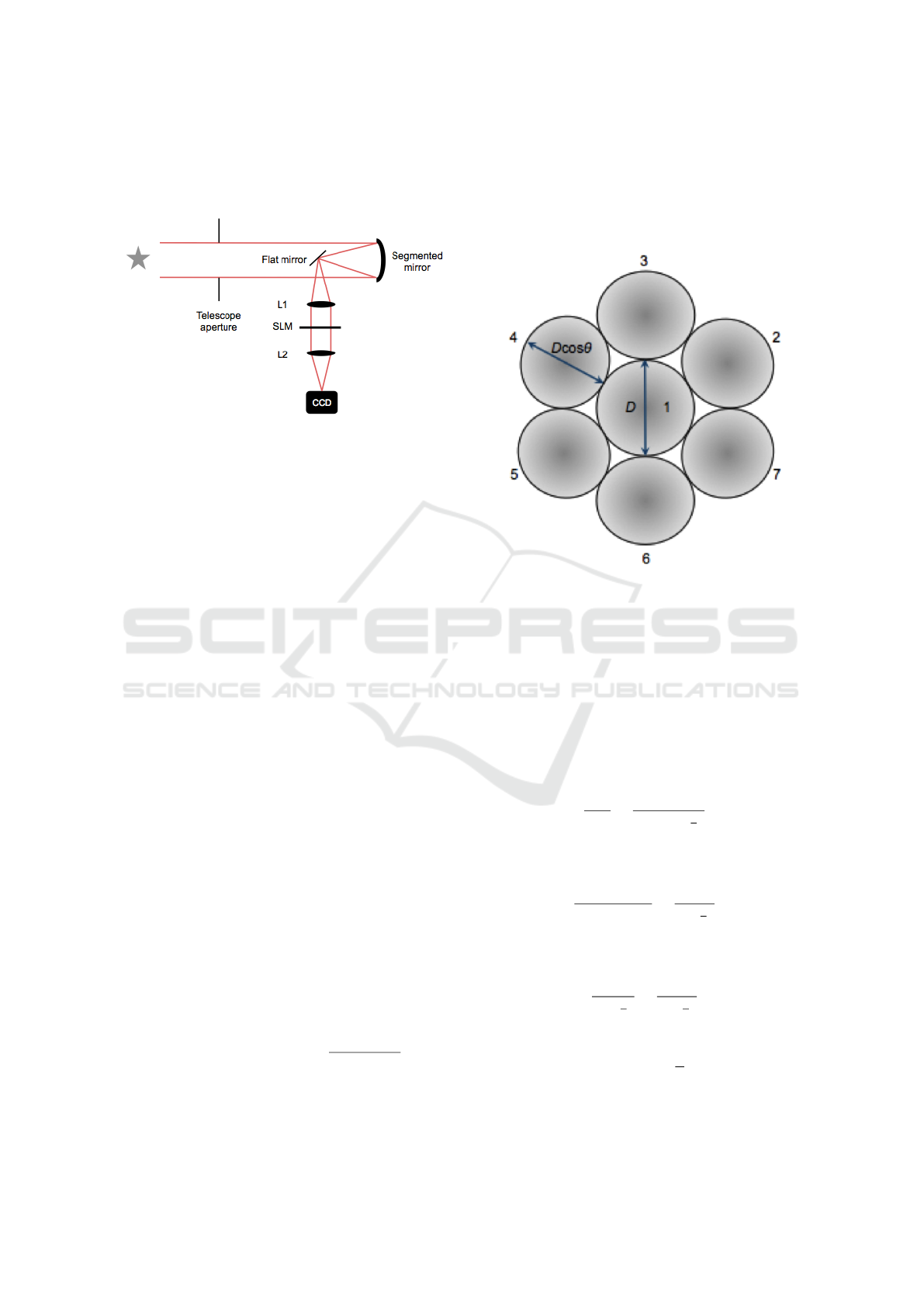
diameter as the segmented telescope. The setup of the
whole system is shown in Figure 1.
Figure 1: Optical setup for wavefront correction.
2.1 PSF Calculation
We simulate the performance of a segmented reflect-
ing telescope using the angular spectrum method. We
represent a plane wave located at z = 0 as U(x,y,0).
The angular spectrum U( f x, f y,0) at this location is
just the Fourier transform of U(x,y,0) given by Equa-
tion 2 (Goodman, 2005).
U( f
x
, f
y
;0) =
Z
∞
−∞
Z
U(x,y,0)exp[−j2πφ]dxdy (2)
where
φ = f
X
x + f
Y
y (3)
To get the field amplitude U(x,y,0), we get the in-
verse Fourier transform as shown in Equation 4.
U(x,y,0) = F
−1
{U( f
x
, f
y
;0)} (4)
Similarly, the angular spectrum at a distance z is
given by Equation 5.
U( f
X
, f
Y
;z) =
Z
∞
−∞
Z
U(x,y,z)exp[−j2πφ)]dxdy
(5)
where the amplitude U(x,y,z) at a distance z is also
given by
U(x,y,z) = F
−1
{U( f
x
, f
y
;z)} (6)
Comparing Equations 2 and 5, the relation be-
tween U(x,y,0) and U(x, y,z) is given by Equation
7.
U(x,y,z) = U(x,y,0)exp( j 2π
q
1 − f
2
X
− f
2
Y
z) (7)
The angular spectrum methods gives us the PSF at
the point (x,y,z);
2.2 Angular Spectrum of the Segmented
Mirrors
The apertures, which are actually the mirrors, are as
shown in Figure 2.
Figure 2: Top view of the configuration of the seven mirror
segments where D is the diameter of the mirror segment
which is equal to 76mm and θ is the tilt angle.
To simulate the PSF of this configuration, the
other mirrors are rotated along the x and y axis with
respect to Mirror 1, which is centered at the origin.
Each mirror must be tilted such that all the foci of
the mirrors coincide. The geometry for determining
the tilt angle is shown in Figure 3.
We use the sine law in 4ABC to obtain the fol-
lowing relation:
d
sinθ
=
f
sin(90 −
θ
2
)
(8)
Using 4CBD, the left hand side in Equation 8 can
be written as
d
sin(180 −θ)
=
r
sin(
θ
2
)
(9)
Using Equation 9 in Equation 8, we get the fol-
lowing relation:
f
cos(
θ
2
)
=
r
sin(
θ
2
)
(10)
such that the tilt angle can now be expressed as:
θ = 2tan
−1
(
r
f
) (11)
This was used to construct the rotation matrices
for each mirror. The angle is found to be 14.4
◦
.Setting
Improving the Point Spread Function of an Aberrated 7-Mirror Segmented Reflecting Telescope using a Spatial Light Modulator
97
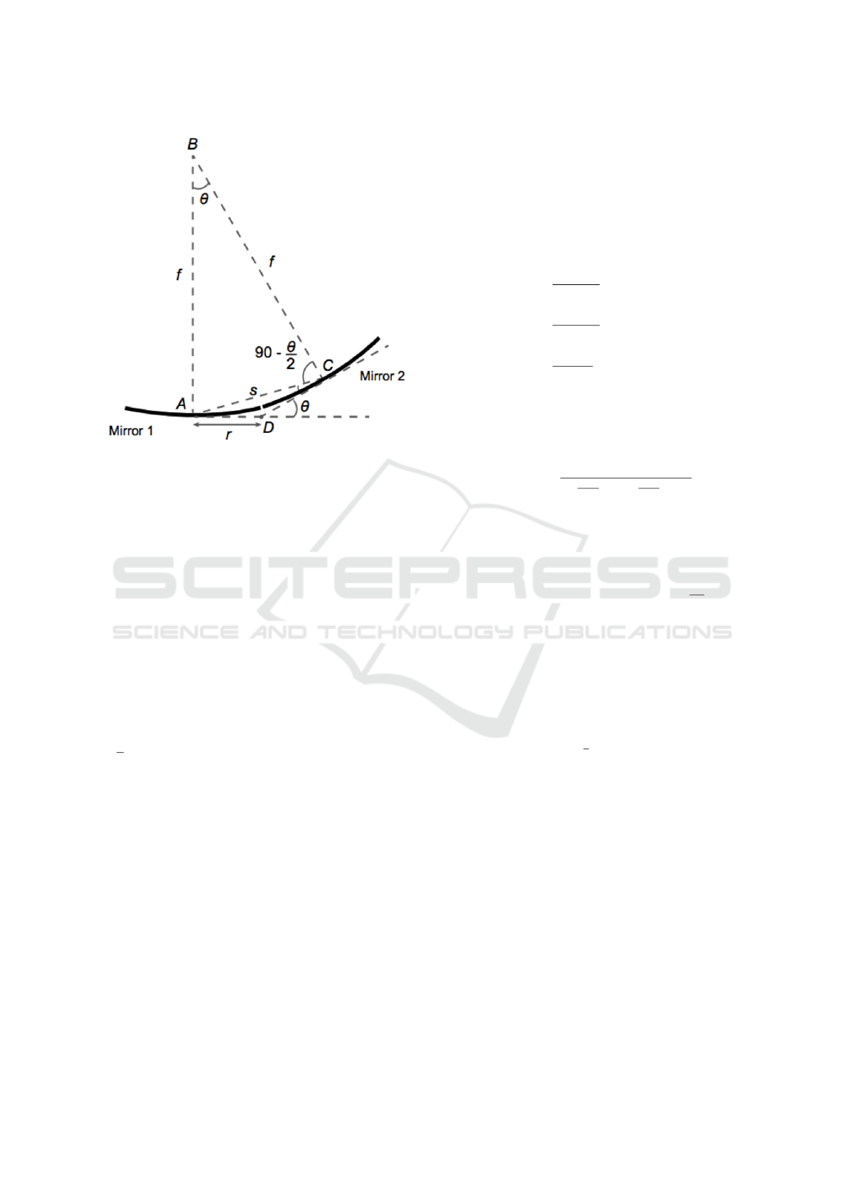
Figure 3: Geometry for determining the tilt angle of mir-
rors.
the optical axis along z, we use the angle to rotate
about the y-axis then the x-axis depending on the po-
sition of the mirror.
R
xy
(α,β) =
cosβ sinα sin β cosα sin β
0 cosα −sin α
−sin β sinα cos β cosα cos β
(12)
The rotation and translation matrices given by
Equations 12 and 14, respectively, were used to ob-
tain the x and y coordinates of the off-axis mirrors as
shown in Equation 13. The angles α and β are both
equal to θ. The variables, dx and dy, are the trans-
lations along the x and y axes, respectively. For the
diagonal mirrors, Mirror 2,4,5 and 7, dx is equal to
√
3r cos(θ) and dy is equal to r cos(θ).
x
0
y
0
z
0
= T
xy
R
xy
x
y
z
(13)
T
xy
=
1 0 dx
0 0 dy
0 0 1
(14)
2.3 Aberration Simulations
Aberrations are deviations in the wavefront which re-
duce the intensity and contrast of an image. They can
be described in terms of Zernike polynomials which
are orthogonal over a unit circle.
Using the Zernike polynomials, the aberration
function can be expressed in terms of polynomials as
shown in Equation 18 (Mahajan, 1994).
W (ρ, θ) =
∞
∑
j=1
a
j
Z
j
(ρ,θ) (15)
where the polynomial ordering number is given by
j, a
j
is the aberration coefficient and
Z
even j
(ρ,θ) =
p
(2n + 1)R
m
n
(ρ)cosmθ m 6= 0
(16a)
Z
odd j
(ρ,θ) =
p
(2n + 1)R
m
n
(ρ)sinmθ m 6= 0
(16b)
Z
j
(ρ,θ) =
p
(n + 1)R
0
n
(ρ) m = 0
(16c)
and
R
m
n
(ρ) =
(n−m)/2
∑
s=0
(−1)
s
(n −s)!
s!(
n+m
2
−s)!(
n−m
2
−s)!
(17)
We used the following aberrations: coma, astig-
matism, spherical aberration and defocus. We simu-
late the aberrations using Equation 18.
PSF
aberrated
= F {F
−1
{PSF
segmented
}exp(i
2π
λ
Φ)}}
(18)
where Φ is given by the following Zernike poly-
nomials (M. Born, 1999)
Φ
sphericalaberration
= 5λρ
4
(19)
Φ
coma
= 0.3λρ
3
cosθ (20)
Φ
astigmatism
= 10λρ
2
cos2θ (21)
Φ
de f ocus
= 8
p
(3)(2ρ
2
−1) (22)
2.4 Wavefront Correction
To correct the wavefront, we needed to calculate the
correcting phase that will serve as the input to the
SLM. The capability of the SLM for wavefront shap-
ing was demonstrated in the photopolymerization of
microgear patterns by encoding in the SLM the topo-
logical charge and phase level of an optical vortexp
(G. Bautista and Daria, 2009). Another work uses the
SLM to reshape light in three dimensions (P.L.A. Hi-
lario and Tapang, 2014). This makes it possible to
correct the aberrations inherent to the telescope. The
phase information from intensity image was retrieved
using the Gerchberg-Saxton (GS) algorithm. From
the intensity image of the PSF, the amplitudes of the
PHOTOPTICS 2016 - 4th International Conference on Photonics, Optics and Laser Technology
98

input data can be obtained by taking the square root
of the measured intensities (Goodman, 2005).
U(x,y) =
p
I(x, y)exp(iφ(x,y)) (23)
Using Equation 23, we first take a guess phase
φ(x,y). We multiply this phase to the amplitude of
the source image and take the Fourier transform. We
take the phase of the resulting complex field and mul-
tiply it with the amplitude of the target image. We
get the inverse Fourier transform and check if the tar-
get image has already been reconstructed. This proce-
dure is repeated until a tolerable reconstruction error
is obtained (R.W. Gerchberg, 1972). A diagram of the
algorithm is shown in Figure 4.
Figure 4: Schematic of the GS algorithm.
For our simulations, we used aberrated PSF of
the segmented mirror as our source and the unaber-
rated PSF of the segmented mirrors as the target. The
phase information retrieved using the GS algorithm
serves as the correction phase. To check if the cor-
rection successful, we denote the correction phase as
Φ
correction
and use Equation 24.
PSF
corrected
= F {|F
−1
{PSF
aberrated
}|exp(iΦ
correction
)}
(24)
The quality of the reconstruction is evaluated us-
ing the Linfoot’s criteria of merit given by Equation
27. When all these values are 1, it means that the
signal was perfectly recovered. If C <1, the recon-
structed profile is narrower than the target profile.
When Q <1, it means that the reconstructed and target
profiles are erroneously close to each other (G.Tapang
and Saloma, 2002).
F = 1 −
< (I
target
−I
reconstructed
)
2
>
< (I
target
)
2
>
(25)
Q =
< (I
reconstructed
)
2
>
< (I
target
)
2
>
(26)
C =
< |I
reconstructed
||I
target
| >
< (I
reconstructed
)
2
>
(27)
3 RESULTS AND DISCUSSION
Figure 5 shows the transverse PSFs of a single mirror
segment, the segmented mirrors and the monolithic
mirror. Adding the fields due to the 7 mirrors, we get
a PSF that is much smaller than the individual mirror
segment. This is expected since the effective aperture
diameter of the segmented mirrors is now larger than
a single mirror.
Taking the cross-section of the PSFs, we see that
the width of the Airy disk of the segmented mirror
is broader than that of the monolithic mirror despite
having the same aperture diameter. This is due to the
segmentation of the reflecting telescope.
Figures 6 and 7 show the results of the aberration
correction. Using the GS algorithm, the added aberra-
tions were corrected. The quality of the correction is
evaluated by computing the Linfoot’s criteria of merit
values of both the aberrated PSF and the corrected
PSF as shown in Table 1.
The SLM in Figure 1 is a transmitting twisted
nematic spatial light modulator such as the Holoeye
LC2012. Modulation in phase occurs when an elec-
tric field is applied causing the molecules to align
themselves along its direction. The correcting phase
obtained using the GS algorithm will be sent to the
SLM via a video signal from the computer. In the ac-
tual experiment, the PSF should be scaled such that
4f =
λ f M
a
where λ is the wavelength, f is the focal
length, M is equal to the pixel dimension and a is the
aperture diameter. We computed 4f to be equal to
640µm.
The use of identical mirrors reduces the cost and
complexity in constructing telescopes with very large
apertures. It eliminates the need to precisely shape
the mirrors which requires each mirror segment to be
polished well up to the edge in order to seamlessly
form one large mirror. Thus, increasing the quantity
production of the mirrors. Mounting the mirror will
also be easier since the structural support will not de-
pend on the individual shape of the mirror segments.
Furthermore, placing an adaptive optics device, such
as the SLM, before the camera allows the incoming
wavefront to be shaped to compensate for any mis-
Improving the Point Spread Function of an Aberrated 7-Mirror Segmented Reflecting Telescope using a Spatial Light Modulator
99
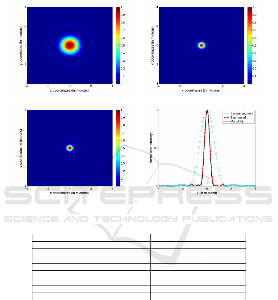
Single Mirror Segment 7 Mirrors
Monolithic Cross-section of the PSFs
Figure 5: PSFs of a single mirror segment, segmented mirror and the monolithic mirror.
Table 1: Linfoot’s criteria of merit for aberrated and the corrected PSF using the angular spectrum method.
Aberration Fidelity Structural Content Correlation
Spherical Aberration Aberrated 0.9670 0.7005 0.8337
Corrected 1.0000 1.0000 0.9988
Coma Aberrated 0.9956 0.9990 0.9973
Corrected 1.0000 1.0000 1.0000
Astigmatism Aberrated 0.0179 0.0137 0.0158
Corrected 0.9843 1.0000 0.9922
Defocus Aberrated 0.0045 0.0022 0.0033
Corrected 0.9843 1.0000 0.9922
alignment and aberrations inherent in the telescope
system.
4 CONCLUSION AND
RECOMMENDATION
We have demonstrated a technique to correct aberra-
tions in a basic segmented reflecting telescope by us-
ing the GS algorithm to obtain the correction phase.
We have numerically evaluated the technique and
have shown that it was able to reduce the effects of
aberrations. Using this technique, we remove the
need for shaping of the individual mirror segments
precisely. The intensity of the side lobes in the PSF
due to errors in alignment can be compensated using
a single SLM. The wavefront can be shaped such that
the imaging resolution can be improved to make it at
par with the performance of one large mirror.
PHOTOPTICS 2016 - 4th International Conference on Photonics, Optics and Laser Technology
100
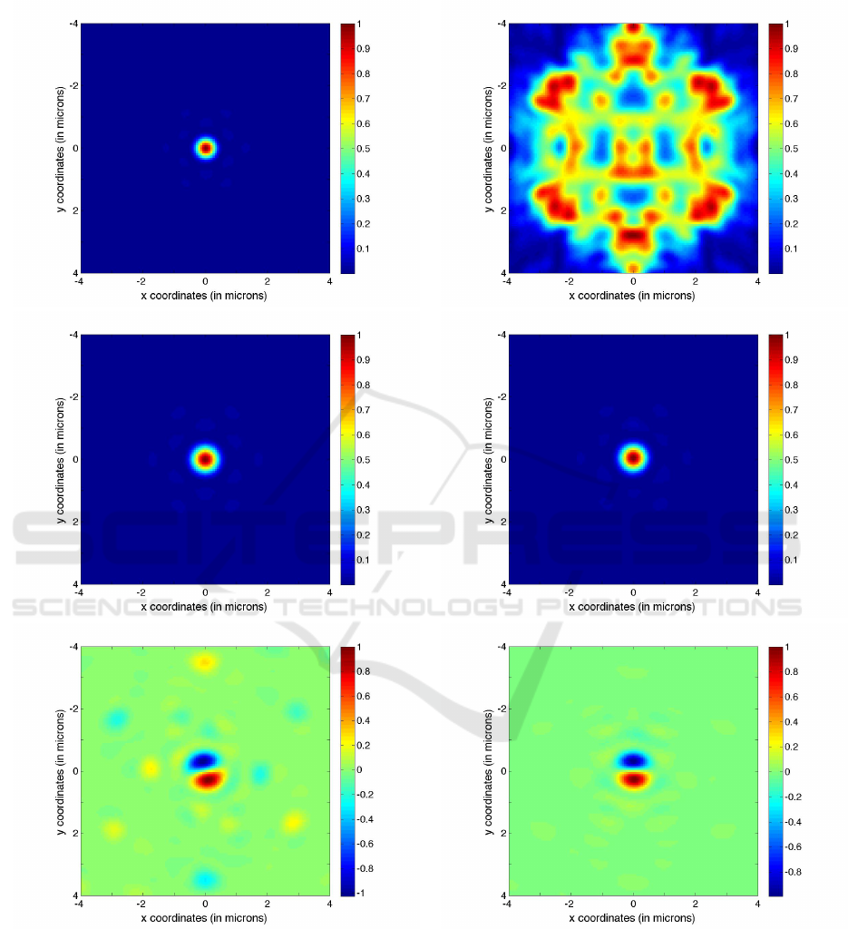
Coma Astigmatism
Figure 6: Aberrated (1st row), corrected (2nd row) and the difference between the target and the corrected PSF of the seg-
mented reflecting telescope.
Improving the Point Spread Function of an Aberrated 7-Mirror Segmented Reflecting Telescope using a Spatial Light Modulator
101
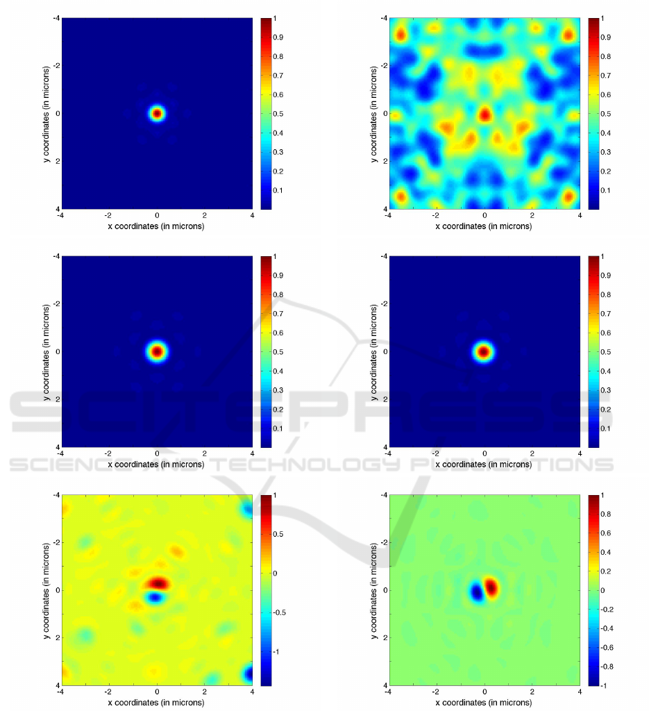
Spherical Aberration Defocus
Figure 7: Aberrated (1st row), corrected (2nd row) and the difference between the target and the corrected PSF of the seg-
mented reflecting telescope.
PHOTOPTICS 2016 - 4th International Conference on Photonics, Optics and Laser Technology
102

REFERENCES
G. Bautista, M.J. Romero, G. T. and Daria, V. (2009). Paral-
lel two-photon photopolymerization of microgear pat-
terns. Optics Communications, 282(18):3746–3750.
G. Chanan, J. Nelson, T. M. (2013). Semented mirror tele-
scopes. In Planets, Stars and Stellar Systems, volume
Volume 1: Telescope and Instrumentation, pages 99–
136. Springer.
Goodman, J. (2005). Introduction to Fourier Optics.
Roberts and Compan Publishers, 3rd edition.
G.Tapang and Saloma, C. (2002). Behavior of the
point-spread function in photon-limited confocal mi-
croscopy. Applied Optics, 41(8):1534–1540.
M. Born, R. W. (1999). Principle of Optics. Cambridge
University Press.
Mahajan, V. (1994). Zernike circle polynomials and optical
aberrations of systems with circular pupils. Supple-
ment to Applied Optics, pages 8121–8124.
P.L.A. Hilario, M. V. and Tapang, G. (2014). Independent
light fields generated using a phase only spatial light
modulator. Optics Letters, 39(7):2036–2039.
R.W. Gerchberg, W. S. (1972). A practical algorithm for
the determination of phase from image and diffraction
plane pictures. Optik, 35(2):237–246.
Improving the Point Spread Function of an Aberrated 7-Mirror Segmented Reflecting Telescope using a Spatial Light Modulator
103
