
Quantitative Evaluation of Security on Cryptographic ICs against
Fault Injection Attacks
C. Shao, H. Li and G. Xu
Shenzhen Institutes of Advanced Technology, Chinese Academy of Sciences, The Chinese University of Hong Kong,
518055, Shenzhen, China
Keywords: Fault Injection Attacks, DFST, Security Evaluation, Quantitative Evaluation, RSA.
Abstract: Fault injection attacks have become a serious threat against cryptographic ICs. However, the traditional
security evaluation often demands experienced engineers repeatedly scan the IC under test for a few hours to
a few days, and take the workload statistics and experiences as qualitative indexes. This paper proposes a
quantitative model to evaluate security based Design for Security Test (DFST), considering both the sensitive
time during the algorithm operation and the sensitive area of the cryptographic IC against fault injection
attacks. The case study on two RSA implementations demonstrates the feasibility of the quantitative
evaluation of security model.
1 INTRODUCTION
Cryptographic integrated circuits (ICs) are dedicated
semiconductor implementations of various
cryptographic algorithm and have been employed in
an increasing number of consumer products, e.g.,
smart cards, cell phones, and set-top boxes, to provide
security and privacy protection. In order to ensure that
the confidential information in cryptographic ICs will
be generated, stored, transmitted and processed safely,
we define security for its information assurance
capabilities with the ability to resist attacks.
Cryptographic modules as one of the information
security products, how to timely and efficiently
evaluate its security to complete their functions, has
issued the relevant international standards and many
scholars have made a research in this are a(Su et al.,
2011).
Cryptographic ICs inevitably become the targets
of numerous attacks, including fault injection attacks.
The fault injection may cause transient logic errors
during the execution of cryptographic algorithms.
The transient errors may bypass the security condition
checks, or be used for differential fault analysis(DFA)
(Barenghi et al., 2012).There are multiple methods to
invoke faults such as variations in supply voltage,
variations in the external clock, temperature
variation, white light, laser, and X-rays and ion beams
(Kim and Quisquater, 2007). The RSA
implementation with Chinese Remainder Theorem
(CRT-RSA) was reported broken by fault attacks with
only one faulty computation (Boneh et al., 2001).
Similarly the secret keys could be compromised from
ECC, DES, AES and RC5 crypto modules etc. (Bar-
El et al., 2006).
The key point of fault injection attack is injecting
a fault in correct location and correct time. Therefore
security evaluation must be done in both time and
space domains. The security evaluation in space
domain is to locate the vulnerable region of
cryptographic ICs under test. The security evaluation
in time domain is to identify the sensitive time period
on the vulnerable region.
The traditional security evaluation often demands
experienced engineers repeatedly scan the IC under
test for a few hours to a few days to obtain effective
results. Take the smart card test for example, it
usually takes 1-5 days for security evaluation against
laser beam attacks (MasterCard International
Incorporated, 2005). On one hand, this is due to the
niche probability of effective fault injection both on
the temporal and the spatial domain. On the other
hand, the traditional way of fault injection test cannot
effectively detect the internal logic errors due to the
limited IO numbers. The requirement on specific and
profound knowledge of cryptographic ICs also makes
it difficult for successful evaluation both in space and
time domains. Besides, location of the vulnerable
region is affected by the attack time, which will cause
Shao, C., Li, H. and Xu, G.
Quantitative Evaluation of Security on Cryptographic ICs against Fault Injection Attacks.
DOI: 10.5220/0005686300970104
In Proceedings of the 2nd International Conference on Information Systems Security and Privacy (ICISSP 2016), pages 97-104
ISBN: 978-989-758-167-0
Copyright
c
2016 by SCITEPRESS – Science and Technology Publications, Lda. All rights reserved
97

inaccurate evaluation results if security evaluation in
space and time are separated.
Motivated by these challenges, we develop a
quantitative model to evaluate the security
considering both the sensitive time and space during
the algorithm operation for cryptographic ICs, which
is based on the proposed design for security test
(DFST) in (Shao et al., 2014) against fault injection
attacks with industrial automatic test equipment
(ATE). A three dimensions (3D) fault map in time
and space can be quickly and accurately obtained,
which helps to locate the error-prone region of
cryptographic ICs. The value representing the
security level can be calculated by the quantitative
model.
Compared to the existing security evaluation, the
main contributions of the proposed security
evaluation method are as follows:
Security evaluation is performed based DFST,
which helps to diagnose the fault occurrence
locations with high accuracy and fault occurrence
time period with high efficiency.
The quantitative model considers both the space
domain and the time domain, which could provide
intuitive understanding and comprehensive
evaluation of cryptographic ICs security against
fault injection attacks.
The rest of the paper is organized as follows. We
briefly introduce the background of fault injection
attacks on cryptographic ICs and security test of
cryptographic ICs with DFST in Section II. In Section
III, we present the evaluation flow based on DFST
method and present the quantitative model
considering both the space and the operation time. In
Section IV, a case study on two RSA implementations
is demonstrated to validate the effectiveness of the
quantitative evaluation model. The study is concluded
in Section V.
2 BACKGROUND
2.1 Fault Injection Attacks
Fault injection attackers aim to maliciously alter the
correct functioning of computing devices, and
analyze the faulty output to retrieve the secret
information, which been listed into Federal
Information Processing Standard FIPS 140-3,
Security Requirements for Cryptographic Modules
(NIST, 2009), generally accepted as one of the
standard security evaluation methods. Fault injection
techniques can be classified in two main categories:
hardware fault injection, and software fault injection
(Ningfang et al., 2011).The hardware fault injection
are of the main interest in this paper, which include
variations in the external clock, variations in supply
voltages, laser illumination, X-rays and ion beams
radiation etc.
The hardware fault injection tools can be
classified by their (temporal and spatial) precision
and the cost (Kim and Quisquater, 2007).
With well-timed power spikes or dropdowns into
the supply line, it is possible to for the device to skip
specific instruction execution. The temporal precision
depends on the voltage drop/spike duration and
synchronization with the target device. Similarly,
altering the length of a single clock cycle may corrupt
data storage, which also requires relatively high
temporal precision.
Electromagnetic (EM) disturbances near the
device may induceddy currents in the circuit, causing
temporary alterations of the signal voltage level.
Laser beam and heavy ion micro beam can cause
abnormal behaviors on semiconductor devices
through single event effects (SEE), where a strong
radiation of a transistor may form a temporary
conductive channel in the dielectric, which, in turn,
may cause the logic circuit to switch state in a precise
and controlled manner.
2.2 Fault Attacks to Break
Cryptosystems
Fault injection has been reported effective on various
crypto modules. DES (Data Encryption Standard)
was reported vulnerable against fault injection attacks
at the15
th
round, an exclusive-OR (XOR) operation
between the correct and faulty cipher text will yield
the 15
th
round-sub keys. An exhaustive search of the
64 possible values of the corresponding substitution
will reveal the left 6-bitsubkey and thus the entire key
(Bar-El et al., 2006). A fault occurs on the 9
th
round
of AES (Advanced Encryption Standard) before Mix
Column operation will also yield the round key
(Moradi et al., 2006).This paper will take the right-to-
left RSA binary implementation with Montgomery
modular multiplication as the example to illustrate the
principle of fault injection attacks.
RSA is one of the first practicable public-key
cryptosystems and is widely used for secure data
transmission, named after Ron Rivest, Adi Shamir
and Leonard Adleman (Rivest et al., 1978). In such a
crypto system, the encryption key is public and differs
from the decryption key which is private and kept
secret. Two distinct and large odd prime numbers p
and q are used to generate two key-pair values: the
ICISSP 2016 - 2nd International Conference on Information Systems Security and Privacy
98

public key-pair (e,N), and the private key-pair (d,N)
(Wang, 2006; Zhang, 2005). The RSA algorithm can
be described as follows:
The modulus N is the product of two large primes
p and q.
Computes e through
()()
()
,111gcd e p q−−=
, where
gcd refers to the function of greatest common divisor
(Hardy and Wright, 1979).
Computes d through
()
1 mod( 1)( 1)de p q⋅= − −
.
The RSA encryption is performed using the public
key e:
mod
e
N
cm=
(1)
Where m is the plaintext,0<m<N, and c is the
ciphertext which can be decrypted using the secret
key d:
mod
d
N
mc=
(2)
An effective fault induced in one of the RSA private
key bits in the binary RSA implementation will result
in a faulty decryption result. With detailed fault
analysis, one can extract the key bit (Bar-El et al.,
2006). The procedure is as following. An attacker
arbitrarily chooses a plaintext m and computes the
cipher-text c. Let us assume there is one bit in secret
key d flipping from 1 to 0 or vice versa with a fault
injection, and the position of the flipped bit is
randomly located, then the attacker obtains a faulty
plaintext
ˆ
m
as the decryption result. Since there is
only one bit flipped, let it be
[]di
flipped to
[]di
]
[id
,
then the division between the faulty and the correct
plaintext will yield:
2[]
2[]
ˆ
(mod )
i
i
di
di
mc
N
m
c
=
(3)
Obviously, if
2
ˆ
1
(mod ) [ ] 1
i
m
Ndi
m
c
= →=
(4)
And if
2
ˆ
(mod ) [ ] 0
i
m
cNdi
m
= →=
(5)
This process is repeated until enough information is
obtained about the secret key d.
RSA using the Chinese Remainder Theorem
(CRT-RSA) is also vulnerable to fault attacks (Kim
and Quisquater, 2007). Let a and b be the pre-
computed values required by the CRT-RSA, there is:
{
{
1mod() 0mod()
0mod( ) 1mod( )
ap b p
and
aq bq
≡≡
≡≡
(6)
And define:
mod ( 1)
mod ( 1)
p
q
dd p
dd q
−
−
=
=
(7)
The RSA signature s is the sum as:
(mod )
pq
sas bs N=+⋅⋅
(8)
Where:
(mod )
(mod )
p
q
p
q
d
d
sm p
sm q
=
=
(9)
If there is a fault injected during the computation of
p
s
or
q
s
, then the faulty signature
(mod )
pq
s
as bs N
′′
=⋅ +⋅
. The subtraction between
the correct and the faulty signature will yield:
()
()mod
qq
s
sbs s N
′′
Δ= − = ⋅ −
(10)
A simple gcd (greatest common divisor) calculation
will factor N:
gcd( , )NpΔ=
(11)
This will compromise the RSA secret key, since we
can easily obtain d with known two large primes p
and q.
2.3 Security Test of Cryptographic ICs
with DFST
Quantitative Evaluation of Security is based on the
proposed design for security test (DFST). In this
section we demonstrate design for security test
(DFST) method and the consequent security test with
ATE on cryptographic ICs proposed in (Shao et al.,
2014), combining DFT and fault injection techniques
to facilitate a fast security test against fault injection
with a low IC area overhead.
Figure 1 demonstrates the relation of different
phases of cryptographic ICs from design to test. The
cryptographic ICs are designed with the proposed
DFST. Security test of cryptographic ICs is
performed by an engineer in a third authentication
party. The designers of cryptographic ICs should
provide the test patterns to the security authentication
party.
Quantitative Evaluation of Security on Cryptographic ICs against Fault Injection Attacks
99
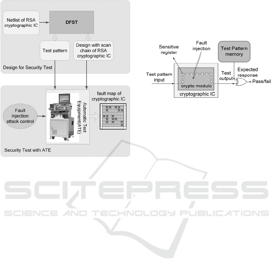
Figure 1: Design for security test (DFST) and Security test
of cryptographic ICs.
The security test only concerns a small fraction of
the internal circuit states, on which an injected fault
will result in an effective faulty
encryption/decryption result. With careful
differential fault analysis, the effective faulty result
will largely reduce the search space of the secret key.
The principle idea of DFST is to observe the internal
states of those vulnerable cells.
The flowchart of DFST is as follows: Firstly, we
identify the sensitive registers with SER analysis as
previously described. Secondly, we mark the
sensitive registers in Register Transfer Level (RTL)
design netlist by prefixing sensitive registers. For
example, in the cryptographic algorithm of the right-
to-left RSA binary implementation with Montgomery
modular multiplication, all the sensitive registers
d[i]are beginning with ‘e_or_d_reg_’. Thirdly, we
only insert those marked registers into scan chains.
Finally, the test patterns are generated with the
commercial Automatic Test Pattern Generation
(ATPG) tools. The test pattern will be used during the
security test.
Once cryptographic ICs are designed for security
test with the proposed DFST, the security test could
be performed with the industrial ATE equipment. The
test structure is illustrated in Figure 2.
The procedures of the security test are as follows:
1) Set the device under test (DUT) in test mode; 2)
Run the test repeatedly with fault injection scanning
the DUT; 3) Compare the test result to the golden
references. If the two results are inconsistent, mark
the area being attacked as the sensitive area; 4) Scan
the whole DUT and form a fault map.
Figure 2: Security test on the cryptographic ICs with DFST.
3 QUANTITATIVE SECURITY
EVALUATION BASED ON DFST
Since the attacks are sensitive in both time and space
domains. We develop the quantitative security
evaluation model accordingly. We first locate the
vulnerable region of the IC under test. Then we
further identify the sensitive time period on the
vulnerable region. Thus we can plot the three-
dimensional (3D) map indicating the vulnerability.
Each fault is represented with a cuboid, the bottom
area stands for the fault injection spot on the chip
layout, and the height stands for the sensitive time
period of the spot. The volume of all the cuboids is
then calculated for quantitative evaluation.
3.1 Security Evaluation in Space
Domain
The aim of security evaluation in space domain is to
locate the vulnerable region of ICs under test. The
cryptographic ICs designed by DFST can facilitate
fast and automatic security test in space domain
against fault injection. The flow of security test with
the DFST is displayed in Figure3.
The procedures of the security evaluation in space
are as follows:
1) Set the security chip designed by DFST in test
mode;
2) Make a scan test of the security chip under fault-
attack;
3) Judge the sensitive area by comparing the scan
output to the expected value and compute number
of fault occurrences n. If the two results are
ICISSP 2016 - 2nd International Conference on Information Systems Security and Privacy
100
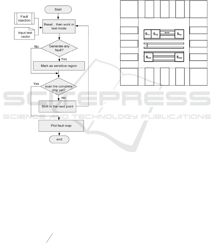
inconsistent, mark the area being attacked as the
sensitive area.
4) Scan the whole chip layout and form a 2D fault
map.
The Security evaluation based DFST can determine
the sensitive region exactly by the output vector and
has nothing to do with the output analysis, which is
much more efficient than security chip without scan
chain.
Figure 3: The flow of security test.
During the security test, the chip surface will be
scanned with various fault injection tools, such as
laser illumination and ion beam irradiation. The chip
can be scanned with any size of fault injection attack
(FIA) spot, which can target from a single transistor
to hundreds of transistors, depending on the
equipment used by the attackers as described in
Section II. Figure 4 illustrates scanning in the security
test, where each scan (S
11
, S
12
…, S
mn
) is scan spot,
which corresponds to scan step and scan precision of
fault injection tool.
The equation for quantitative security in space
domain
QS
S
for the entire chip is as:
=
QS
n
S
N
(12)
Where N denotes the total number of the fault
injection evenly traversing the entire IC, which
depends on the entire chip area, each injection spot
size and scan step; n denotes the number of fault
occurrences;
QS
S
denotes the percentage of the
sensitive area in the whole chip. A larger value of
QS
S
indicates a lower security level.
Figure 4: Fault injection scan on the cryptographic ICs with
DFST.
3.2 Security Evaluation in Time
Domain
Since security evaluation in time domain aims to
locate the vulnerable time regions of marked
vulnerable locations during the cryptographic
algorithm execution, the cryptographic IC should
work in function mode. In order to flexible control
fault injection, security evaluation in time domain is
operated by the method of function simulation. The
procedures are as follows:
1) Select a sensitive logic cell from marked
vulnerable locations and inject faults at certain
time intervals. Fault can be injected by the
simulation tools. The time interval of fault
injection is flexible. A short interval usually
means finer operation but longer evaluation cycle.
We recommend one clock cycle as the time
interval for the simulation of each fault injection.
2) Analysis the encryption/decryption results and
judge the sensitive time. If the result generates a
valid error, mark the time interval as the
Quantitative Evaluation of Security on Cryptographic ICs against Fault Injection Attacks
101

sensitive time.
3) Traverse the entire encryption/decryption period
under fault injection at certain time intervals.
4) Move to the next a sensitive point and repeat the
above steps.
5) Traverse all sensitive logic cells from marked
vulnerable locations of 2D fault map. Then plot
the sensitive time period for corresponding
sensitive logic cells and form 3D fault map. Each
fault is represented with a cuboid.
The volume V of the sensitive regions is calculated as:
)()(
1
isitV
n
i
=
⋅=
(13)
Where n denotes the total number of the sensitive
spots in space; i denotes the ith spot that exhibits a
fault; s(i) denotes the area of the i
th
fault injection
spot; t(i) denotes the time during of the fault on the i
th
spot.
Eq. (13) does not take into account of the parallel
and the serial implementations of the same
cryptographic algorithm. A parallel implementation
usually occupies larger IC footprint than the serial
implementation, but takes shorter time. To eliminate
the effect from parallel and serial operation of the
same function, Eq. (13) could be updated through
normalization:
TS
isit
S
n
i
Q
∗
⋅
=
=1
)()(
(14)
Where S denotes the entire IC area, T denotes the
entire time for each cryptographic execution cycle. A
bigger value of
Q
S
indicates a lower security level.
4 CASE STUDY
4.1 Security Quantitative Evaluation
Method Based RSA
In this section, we demonstrate the quantitative
evaluation with the implementation of a 1024-bit
RSA cryptosystem. The RSA module is the right-to-
left binary algorithm with Montgomery modular
multiplication. The design mainly includes an 8051
microprocessor, memory, a bus controller, a random
number generator (RNG), the RSA encryption and
the decryption module. The procedure of security
quantitative evaluation for the RSA cryptographic IC
is divided into two steps: design for security test and
security quantitative evaluation. The detailed flow is
as follows:
1) Design for Security Test:
The key registers d[i] are identified as the
sensitive registers.
Mark the sensitive registers by defining the
registers’ names with the prefix “e_or_d_reg_” in
the netlist.
Insert the scan-chain around the marked sensitive
registers and output the original DFT gate-level
netlist. The DFT commands such as
“set_scan_path” and “set_scan_element
true/false” are able to separate the sensitive
registers from other registers.
Generate the test patterns out of TetraMax
TM
, a
commercial ATPG tool.
Generate the physical layout of the RSA
implementation t.
2) Quantitative Evaluation of Security:
Set the RSA cryptographic IC designed by DFST
in test mode.
Make a scan test of the RSA cryptographic IC
under fault-attack in Automatic Test Equipment.
Perform the quantitative security evaluation in
space domain by simulating the fault injection
test, and plot the 2D fault map.
Perform the quantitative security evaluation in
time domain, and plot the 3D fault map.
4.2 Experimental Results
In our simulation, the scan registers are synthesized
with Synopsys Design Compiler™, the scan chains
are inserted with DFT Complier™, the test patterns
are generated from the ATPG tool TetraMax™, and
the circuit simulator is chosen to be VCS™. Other
similar tools can also be used. We identify 2048
sensitive registers and insert 6 scan-chains, which
accounts for an area overhead of 0.6%. For our RSA
implementation and the necessary peripheral circuits
of 740,000 logic gates, the area of cryptographic IC
design of RSA is 36mm
2
, with the technology
of0.18um GSMC. Laser illumination is selected as
fault injection source, and a laser spot size is selected
to be 10umx 10umlarge.
Figure 5 demonstrates the 2D fault map of the
RSA cryptographic IC design. The crosses indicate
the faults (not one by one indication due to the image
resolution limit). The sensitive registers contain two
types: key_ed[i] and e_or_d[i]. The total number of
laser illumination traversing the entire chip is 360000,
ICISSP 2016 - 2nd International Conference on Information Systems Security and Privacy
102
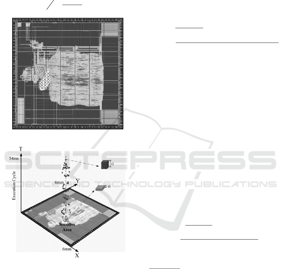
among which the number to successfully inject faults
is 4248. Then the quantitative security evaluation of
our test chip in space domain for the entire chip is
calculated as:
%18.1
360000
4248
===
N
n
S
QS
Figure 5: 2D fault map of the binary RSA design.
Figure 6: 3D fault map of the binary RSA design.
Figure 6 demonstrates the of the 3D fault map of
the cryptographic IC design of the binary RSA
implementation. The die area of cryptographic IC
design of RSA is 36mm
2
and the length of the RSA
decryption time is about 54ms. The number of
sensitive spots related to the registers key_ed[i] is
2016, shown with the pink short blocks at the bottom.
The sensitive time interval for key_ed[i] is 50ns, as
‘t1’exemplifies. The number of sensitive spots related
to the registers e_or_d[i] is 2232, shown with the blue
blocks along the time axis. The sensitive time interval
for e_or_d[i] is 51400ns, as ‘t2’exemplifies. The area
of each register in technology library of0.18um
GSMC is 66.5um
2
.
The quantitative security evaluation of the right-
to-left binary implementation of RSA is then
calculated as:
1
_
2
62 6
6
() ()
(50 2016 51400 2232) 66.5
36 10 54 10
3.9 10
n
i
Q binary
ti si
S
ST
ns ns um
um ns
=
−
⋅
=
∗
×+ × ×
=
×∗×
=×
Various implementations will have different values of
quantitative security evaluation. The CRT-RSA has
much larger value than the binary RSA, since CRT-
RSA has much larger sensitive area: the whole sub-
modules computing
p
s
and
q
s
.Furthermore, each
sensitive spot will be vulnerable for a long time along
the execution cycle, since the fault injection attack
works on binary RSA if and only if one bit is changed,
but there is no such limit on CRT-RSA.
For our CRT-RSA implementation and the
necessary peripheral circuits of 983,000 logic gates,
there are 21633 sensitive registers. The total layout
area is 72mm
2
, the number of sensitive logic cells in
sub-modules computing sp or sq is 519401. The area
of a standard cell in technology library of0.18um
GSMC is 13.5um
2
.Each of the computation of s
p
and
s
q
roughly takes 27ms. Then the quantitative security
evaluation of the CRT-RSA implementation is
calculated as:
1
_
62
62 6
() ()
2(27 10 519401) 13.5
0.19
72 10 27 10
n
i
Q CRT RSA
ti si
S
ST
ns um
um ns
=
−
⋅
=
∗
×× ×
==
×∗×
This indicates that CRT-RSA is almost
_
_
48717
Q CRT RSA
Q binary
S
S
−
=
times more vulnerable against
the fault injection attacks. The result is quite contrary
to previous observation that CRT-RSA is superior
compared to the right-to-left binary implementation,
in terms of better security against simple power
analysis etc. This quantitative evaluation model can
help the product designers to select the appropriate
implementation, considering potential attack
environments.
Quantitative Evaluation of Security on Cryptographic ICs against Fault Injection Attacks
103

5 CONCLUSIONS
The security evaluation against fault injection attacks
is challenging due to the niche probability of effective
fault injection both on the temporal and spatial
domain and the difficulty in observing internal
transient logic errors. This paper proposes a
quantitative model to evaluate security based DFST
against fault injection attacks, considering both the
operation time and the sensitive area of the
cryptographic ICs. Simulation results on two RSA
implementations demonstrate the feasibility of the
design for security test method and the evaluation
model, which can be easily extend to implementation
of other cryptographic algorithms. Further work is to
improve the efficiency of the security evaluation
with automated scripts.
ACKNOWLEDGEMENTS
This work was supported by Shenzhen S&T Funding
with Grant No. JCYJ20140417113430591,
GJHZ20140417113430584,
CXZZ20140527172356968,
JSGG20150511104613104, Guangdong S&T
Funding 2013B050800003, 2015B010106004 and
China National S&T Major Project with Grant No.
2014ZX01032401-001.
REFERENCES
Su, D., Xu, K. and Gao, Y., 2011. The Evaluation Model
and Index System of Cryptographic Modules Security
Assurance Ability. Proceedings of Third International
Conference on Multimedia Information Networking
and Security, pp. 448-452.
Barenghi, A., Breveglieri, L., Koren, I. and Naccache, D.,
2012. Fault injection attacks on cryptographic devices:
Theory, practice, and countermeasures. Proceedings of
the IEEE, vol. 100, no. 11, pp. 3056—3076.
Kim, C.H. and Quisquater, J. J., 2007. Fault attacks for CRT
based RSA: New attacks, new results, and new
countermeasures. In: Information Security Theory and
Practices. Smart Cards, Mobile and Ubiquitous
Computing Systems, pp. 215—228.
Boneh, D., De Millo, R. A. and Lipton, R. J., 2001. On the
importance of eliminating errors in cryptographic
computations. Journal of cryptology, vol. 14, no. 2, pp.
101—119.
Bar-El, H., Choukri, H., Naccache, D., et al, 2006. The
sorcerer's apprentice guide to fault attacks. Proceedings
of the IEEE, vol. 94, no.2, pp. 370—382.
MasterCard International Incorporated, 2005. Security
Guidelines for Smart Card Integrated Circuits.
Shao, C., Li, H., Xu, G., et al, 2014. Design for security test
against fault injection attacks. Electronics Letters. vol.
50, no. 23, pp. 1677-1678.
The National Institute of Standards and Technology
(NIST), 2009. Security Requirements for
Cryptographic Modules. FIPSPUB140-3 Draft.
Ningfang, S., Jiaomei, Q., Xiong, P., et al, 2011. Fault
Injection Methodology and Tools. Electronics and
Optoelectronics (ICEOE), pp. 47—50.
Moradi, A., Shalmani, M. T. M., and Salmasizadeh, M.,
2006. A generalized method of differential fault attack
against AES cryptosystem. In Proc. Cryptographic
Hardware and Embedded Systems-CHES, Springer
Berlin Heidelberg, pp. 91-100.
Rivest, R. L., Shamir, A., and Adleman, L., 1978. A method
for obtaining digital signatures and public-key
cryptosystems.in Communications of the ACM, vol. 21,
pp.120-126.
Wang, J., 2006. Research of RSA Encryption Algorithm.
Shenyang University thesis.
Zhang, L., 2005. Research and Implementation of RSA
Cryptography. Shandong University of Science and
Technology thesis.
Hardy, G. H., and Wright, E. M., 1979. An introduction to
the theory of numbers. The Clarendon Press Oxford
University Press, fifth edition.
ICISSP 2016 - 2nd International Conference on Information Systems Security and Privacy
104
