
Translating Task Models to State Machines
Andreas Wagner
1
and Christian Prehofer
2
1
itestra GmbH, M
¨
unchen, Germany
3
2
fortiss GmbH, M
¨
unchen, Germany
Keywords:
Task Models, Statecharts, Partial State Machines, Model Transformation, Interaction Modeling.
Abstract:
We present a new method to translate the established and well-known ConcurTaskTree (CTT) task modeling
technique into state machines. For this purpose, we develop the concepts of partial state machines, Connecta-
bles and a connect operator, which form the theoretical framework for a new algorithm. For the translation,
we develop and present a recursive, bottom-up algorithm, which exploits the inherent structure of CTTs and
produces valid, partial state machines. This allows new development processes in the model-driven application
and system development domain.
1 INTRODUCTION
Task models are a widely used technique to model
user interaction with a system. They describe a set
of possible arrangements of basic tasks, which can
be executed to achieve the overall goal. ConcurTask-
Trees (CTT) (Patern
`
o, 2000) are one of the most well-
known approaches to task modeling. Key features of
CTTs include focus on activities, hierarchical struc-
ture, graphical syntax and a rich set of temporal op-
erators (Patern
`
o, 2001). The hierarchical structure of
CTTs allows for the decomposition of complex tasks
into more fine-grained child tasks. Relationships be-
tween tasks are defined via temporal operators be-
tween adjacent siblings. For the purpose of this work,
we focus on the key CTT operators Enabling (>>) ,
Choice ([]), Concurrent (|||) and Disabling ([>).
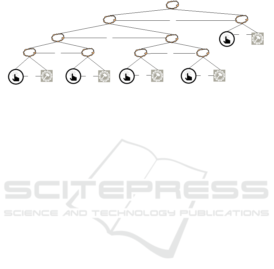
As an example, consider the (simplified) CTT of
operating a TV as depicted in Figure 1. It consists
of ten tasks, which implement the basic features of a
TV like switching channels, adjusting the volume and
putting the TV in standby mode. For instance, if the
next channel should be selected, the user has to initi-
ate the channel switch by pushing the “Chan+” button
and the TV performs the necessary action. Further,
channel switching and adjusting the volume should
be possible to be done in parallel. By turning the TV
off, all other tasks are interrupted.
In this work, we present a recursive algorithm to
translate CTTs, based on their tree structure, into state
3
research carried out at Technische Universit
¨
at M
¨
unchen
machines. Contrarily to existing work on CTT-to-
state-machine-translation (e.g. (Luyten and Clerckx,
2003) or (Van Den Bergh and Coninx, 2007)), our al-
gorithm is a fully recursive, structure- and semantic-
preserving approach to create executable state ma-
chines from CTTs. As the major technical contribu-
tion of this paper, we provide ways to manage and
build intermediate state machines, which are incom-
plete or partial state machines and are composed in
a recursive way. We develop and present the con-
cepts of partial state machines and partial state ma-
chine containers.
One reason why the translation into state ma-
chines is challenging is that the actual input events are
in the leaves of the CTT, but the CTT semantics is pre-
sented recursively in a top down fashion. Hence, a re-
cursive algorithm must carefully compose the partial
state machines and ensure at any time that the correct
set of possible input events is maintained. This issue
can be demonstrated in our TV example. The choice
between the subtree “Increase Volume” (i.e. “Press
Vol+ Button”) and “Decrease Volume” (i.e. “Press
Vol- Button”) must be passed along the whole tree hi-
erarchie, because both tasks may ultimately be used to
as first interaction. A fully-recursive algorithm must
consider this behaviour. While existing work in this
area often relies on some precalculated information
(so called “Enabled Task Sets”, e.g. (Luyten and Cler-
ckx, 2003) or (Van Den Bergh and Coninx, 2007)),
our algorithm maintains the correct input events on
the fly.
Wagner, A. and Prehofer, C.
Translating Task Models to State Machines.
DOI: 10.5220/0005681702010208
In Proceedings of the 4th International Conference on Model-Dr iven Engineering and Software Development (MODELSWARD 2016), pages 201-208
ISBN: 978-989-758-168-7
Copyright
c
2016 by SCITEPRESS – Science and Technology Publications, Lda. All rights reser ved
201
Operate TV
Increase
Volume
Press Chan+
Bu#on
Go to next
Channel
Press Vol+
Bu#on
>>
>>
|||
[ ]
Next Channel
Prev Channel
Press Chan-
Bu#on
Go to prev
Channel
>>
[ ]
Increase Volume Decrease Volume
Decrease
Volume
Press Vol-
Bu#on
>>
Channel Selecon
Volume Selecon
Goto
Standby
Press Standby
Bu#on
>>
Standby
[>
TV
Figure 1: Simple CTT for operating a TV.
2 STATECHARTS
In this work, we follow statecharts as defined in (Es-
huis, 2009) and (Pnueli and Shalev, 1991):
Definition 1. A statechart SC is a tuple τ = (S, T, E),
where
• S is a set of states
• T is a set of transitions
• E is the set of events that transitions
For a given set S, which represents the set of all
states and P (S) being the powerset of S, the function
substates : S 7→ P (S) maps a given state s to the set of
its immediate children.
States may have a property initial, which indi-
cates if a given state is an initial state. The function
isInitial : S 7→ {true, f alse} assigns each state an in-
dicator whether it is initial or not. Basic states are
defined by means of the substates function. If the sub-
states set is empty for a state s ∈ S, i.e. substates(s) =
/
0, then s is called a “basic state”. Basic states may
have a final property (Omg, 2004). To check whether
a basic state is final or not, we use the function
isFinal : S
B
7→ {true, f alse}, which for an element of
the set of all basic states S
B
indicates if the state is
final or not.
Like basic states, composite states are defined by
means of the substates function. If the substates set
is not empty for a state s ∈ S, i.e. substates(s) 6=
/
0, then s is called a “composite state”. Compos-
ite states must be either of type AND or OR. If
S
C
is the set of all composite states, the function
type : S
C
7→ {AND, OR} assigns for each composite
state its type (Pnueli and Shalev, 1991).
OR-States indicate sequential behavior (Eshuis,
2009). An OR-State is defined by means of the
substates function and the type function (Pnueli and
Shalev, 1991). If a state s ∈ S is of type OR and has
substates, i.e. substates(s) 6=
/
0 ∧ type(s) = OR it is
called “OR-State”. The set of all OR-States is de-
noted S
OR
. It especially holds that when the state-
chart is in state s, it is also in one and only one state
s
0
∈ substates(s).
Throughout this work, we call OR-States com-
pound or hierarchical states. Each compound state
s has an initial state s
init
, which is an element of
substates(s). The initial state can be obtained by the
function initial : S
OR
7→ S.
AND or parallel states indicate parallel behav-
ior (Eshuis, 2009). Analogously to OR-States, AND-
States are defined by means of the substates and type
function (Pnueli and Shalev, 1991). If a state s ∈ S
is of type AND and has substates, i.e. substates(s) 6=
/
0 ∧type(s) = AND it is called “AND-State”.
When the statechart is in state s, it is simultane-
ously in all states s
0
∈ substates(s). Further, we re-
quire the substates s
0
∈ substates(s) to be composite
states.
Like states, transitions have properties which can
be obtained by corresponding functions. First, we
denote the set of all transitions T and introduce the
functions source and target on it. Both source : T 7→
S ∪ {null} and target : T 7→ S ∪ {null} are partial
functions which for a transition t ∈ T either return
a s ∈ S or null if source(t) respectively target(t) is
undefined.
More details on the employed functions and pred-
icates for state machines can be found in (Wagner,
2015).
3 PARTIAL STATE MACHINES
Partial State Machines will be be used as intermediate
results of the translation algorithm. To combine par-
MODELSWARD 2016 - 4th International Conference on Model-Driven Engineering and Software Development
202
tial state machines, we use the concept of Connecta-
bles and a connect operator, as defined below.
Connectables are basically well-defined interfaces
for the composition of partial state machines. Con-
nectables rely on free transitions, which we define
first. A transition t ∈ T is said to be free iff target(t) =
null ∨ source(t) = null. We denote the set of all free
transitions T
f ree
and the complementary set of non-
free transitions T \ T
f ree
= T
non f ree
.
With the definition of free transitions at hand,
Connectables can be defined:
Definition 2. Let S
B
be the set of all basic states, S
C
be the set of all compound states and S
P
be the set of
all parallel states. Further, let T
f ree
be the set of all
free transitions. A Connectable c is then defined as
c ∈ (S
B
∪ S
C
∪ S
P
∪ T
f ree
)
Consequently, a Connectable is an abstrac-
tion over states and transitions. Often the ac-
tual type of a Connectable is needed. For
this purpose, we use the function role : C 7→ R,
where R = {Transition, BasicState,CompoundState,
ParallelState} is the set of all roles and C is the set
of all Connectables.
Partial state machines (PSMs) are a superset of
statecharts, which includes “incomplete” statecharts
where e.g. transitions may not lead to a state. We
define PSMs as follows:
Definition 3. A partial state machine is a tuple τ =
(S, T, E, δ) where
• S ⊂ (S
B
∪ S
C
∪ S
P
) is a set of states
• T ⊂ (T
f ree
∪ T
non f ree
) is a set of transitions
• E is a set of events that trigger transitions
• δ : S x T 7→ S is a partial transition function
S and T may be empty, however the restriction holds
that if S =
/
0, T 6=
/
0 and vice versa.
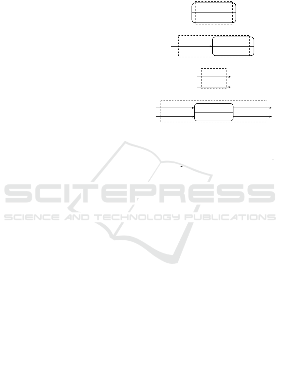
Figure 2 shows - in bold lines - some examples
for (simple) partial state machines (the dotted lines
are explained below).
Next we introduce in and out sets on PSMs. Both
sets are in essence a set of the “dangling” components
of the PSM. As in set I we denote all free transitions
of a PSM which don’t have a source state and all states
which don’t have ingoing transitions. Consequently,
the out set O of a PSM consists of all free transitions
which don’t have a target state and all states which
don’t have outgoing transitions. Note that both I and
O may contain basic, compound or parallel states.
Further, we define that I consists of only transitions or
exactly one state. As an example consider the PSM in
Figure 2(d). The in set consists of the two (free) tran-
sitions “EventA x” and “EventA y”, whereas the out
StateA_x
(a)
EventA_x
StateA_x
(b)
EventA_x
EventA_y
(c)
EventA_x
EventA_y
StateB_x
EventB_x
EventB_y
(d)
Figure 2: Examples for partial state machines and corre-
sponding containers (in dotted lines).
set consists of the two (free) transitions “EventB x”
and “EventB y”. A formal definition of in and out
sets can be found in (Wagner, 2015).
Finally, we need a function states : P 7→ P (S),
which returns all the states (basic states, compound
states, parallel states) of a given PSM. With the in
sets, states set and out sets, we can define the concept
of PSM containers:
Definition 4. Let P be a partial state machine, T
P
the
set of transitions of P and S
P
the set of states of P. A
partial state machine container P
C
is then a 3-tuple
τ = (I
P
, O
P
, S
P
) where
• I
P
is the in set of P with I
P
6=
/
0
• O
P
is the out set of P with O
P
6=
/
0
• S
P
is the set of states of P
Obviously, a PSM container is an abstratcion over
a PSM, which hides the internal structure and only
exposes its interfaces (i.e. Connectables) to the out-
side world. Figure 2 shows - in dotted lines - the PSM
containers for the PSMs in this figure. Note that the
corresponding container of a PSM can be calculated
at runtime by means of the in, out and states func-
tions. Therefore, we will often use the terms partial
state machine (PSM) and partial state machine con-
tainer (PSM
C
) interchangeably throughout this work.
This is only for convenience and does not have any
implications on the translation algorithms.
Finally, the connect-operator (denoted by
connect
−→ )
is a binary function which maps Connectables to sets
of states and transitions. It takes two Connectables
c
1
and c
2
as parameters and returns a set consist-
ing of states and transitions with modified properties.
Translating Task Models to State Machines
203

Most importantly, the
connect
−→ -operator guarantees that
the Connectables c
1
and c
2
are connected in a proper
way, i.e. a state is followed by a transition and vice
versa. Informally, its purpose is to check if two Con-
nectables can be connected and to return the possible
connections. We will use it to connect two Connecta-
bles of different partial state machines.
The
connect
−→ -operator is formally defined as follows:
Definition 5. Let C be the set of all Connectables,
S = S
B
∪S
C
∪S
P
be the set of all states and T = T
f ree
∪
T
non f ree
be the set of all transitions. Further, let X =
S ∪ T and P (X) the powerset of X. Then the function
connect
−→ is defined as
connect
−→ : C x C 7→ P (X )
For its behavior, four cases have to be distin-
guished. If a Connectable c
1
is a (free) transition and
a Connectable c
2
is a (free) transition, then c
1
is con-
nected to c
2
by means of an intermediate basic state
s
intermediate
. The target of c
1
then points to s
intermediate
,
the outgoingTransitions set of s
intermediate
contains c
2
,
the ingoingTransitions set of s
intermediate
contains c
1
and the source of c
2
points to s
intermediate
.
If c
1
is a (free) transition and c
2
is a state, then c
1
is
directly connected to c
2
. The target of c
1
then points
to c
2
and the ingoingTransitions set of c
2
contains c
1
.
The reverse case is handled analogously. Finally, if c
1
is a state and c
2
is a state, then c
1
is connected to c
2
by
means of an intermediate transition t
intermediate
. The
outgoingTransitions set of c
1
and the ingoingTransi-
tions set of c
2
then contain t
intermediate
, the target of
t
intermediate
points to c
2
and the source of t
intermediate
points to c
1
.
4 TRANSLATION RULES
The translation of CTTs into state machines is based
on a recursive algorithm, where each recursive call
returns a partial state machine. The algorithm is de-
scribed in full detail (including proof-sketches em-
ploying induction) in (Wagner, 2015).
We start by explaining the basic case of the re-
cursion, namely tasks. Tasks are the leafs of a CTT.
Within an application, they perform the actual com-
putations, enable the user to interact with the system,
or provide feedback to the user and the environment.
For the translation, we only cover interaction tasks
and application tasks. The type of a task directly in-
fluences its counterpart in the resulting PSM.
Interaction tasks require some sort of interaction
with the user and/or environment, thus being always
bound to a specific event. Events move the system for-
ward and may initiate an arbitrary computation or re-
sponse from the system. In state machines, events are
represented as transitions (e.g. (Harel, 1987)). Thus,
we translate an interaction task into a transition.
On the other hand, it is statically known that an ap-
plication task is performed on the device and does not
require any interaction with the user. Because of this,
an application task can be seen as an isolated com-
putation unit, which is entered when the computation
must be done and left when the computation finished.
We therefore translate an application task into a basic
state.
Besides the events which correspond to interac-
tion tasks, additional events must be introduced which
notify the system about the completion of application
tasks (i.e. that states finished their execution). These
events are called notification events and trigger noti-
fication transitions, which are attached to the states
which correspond to the application tasks.
As an additional step, the generated states and
transitions must be wrapped into a partial state ma-
chine container PSM
Interaction
and PSM
Application
re-
spectively, which provide the Connectables for sub-
sequent connection operations. For interaction tasks,
the transition is the only element created, it is simply
returned as both in and out set of the PSM. For appli-
cation tasks, the created state is returned as in set and
the notification transition is returned as out set.
With the translation rules for the base case (i.e.
tasks) at hand, we can now translate the CTT opera-
tors. In the follwing, we consider translations for the
Enabling, Choice, Concurrent and Disabling opera-
tors. As other operators do not add essentially new
concepts, we expect that the translation scheme can
be extended to other operators analogously.
Note that CTT execution is in general non-
deterministic, as there are choices to be taken in
Choice, Concurrent and Disabling operators. We will
assume that these choices are essentially taken by ex-
ternal user interactions and not by random decisions.
In case such non-determinism is desired, it can be
modeled by external components which take the re-
quired decisions. For the purpose of specifying our
assumption, we use the function first, which is intro-
duced in (Patern
`
o, 2000). The informal purpose of
this function is to return a set of tasks which should be
executed first, given a CTT or a subtree. We require
that the f irst set for all Disabling, Concurrent and
Choice operators consists of only interaction tasks
(i.e. tasks which require user interaction). Thus we
can make sure that choices are always resolved exter-
nally (i.e. by the user).
MODELSWARD 2016 - 4th International Conference on Model-Driven Engineering and Software Development
204
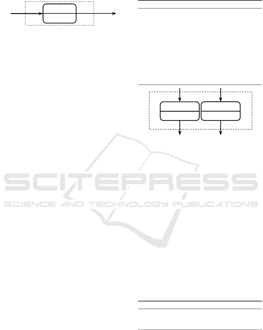
Go to next Channel
Go to next Channel finished
Press Chan+ Button
Figure 3: PSM
Enabling
for sub-CTT “Next Channel”.
4.1 Enabling Operator
According to the CTT specification provided in (Pa-
tern
`
o et al., 2012), the semantics of Enabling requires
the second task not to be activated until the first task
is performed. This establishes a strictly sequential
relation between the tasks of the operator. The par-
tial state machine representing the Enabling operator
must guarantee that this relation between α and β is
preserved during the execution phase (i.e. that α must
be executed before β in any case).
The actual translation of a CTT α >> β is shown
in Algorithm 1. To seize on our example of Figure 1,
we apply the algorithm to the Enabling operator with
α being the task “Press Chan+ Button” and β being
the task “Go to next Channel”. First, the algorithm
creates partial state machine containers PSM
α
for α
and PSM
β
for β by applying the recursive translation
function translate to both tasks (or subtrees in gen-
eral). The connection between both PSMs is done by
connecting each component of out(PSM
α
) (which is
a transition representing the “press button” task) with
each component of in(PSM
β
) (a state representing the
“goto” task) by means of the
connect
−→ -operator. Note
that in general, in(PSM
β
) either contains only transi-
tions or exactly one state. This is ensured by the def-
inition of the in set and the aforementioned require-
ments on the CTT.
The result of the connection operation is a new
partial state machine PSM
Enabling
that contains transi-
tions and states from PSM
α
and PSM
β
as well as addi-
tional states introduced by the
connect
−→ -operator (Figure
3). The in set of PSM
Enabling
is the in set of PSM
α
and the out set of PSM
Enabling
is the out set of PSM
β
.
Note that for further connections, only the Connecta-
bles of PSM
Enabling
are relevant. The contents of the
PSM container do not affect the translation of the up-
per operators.
4.2 Choice Operator
The Choice operator is described by Patern
`
o to of-
fer two tasks/subtrees and “once one has started the
other one is no longer enabled” (Patern
`
o et al., 2012).
For our translation algorithm, we assume that choices
always start with interaction tasks, as defined before-
hand. Thus, we avoid any kind of of possible non-
Algorithm 1: translate(Enabling(α, β)).
PSM
α
← translate(α)
PSM
β
← translate(β)
inter ←
/
0
for all o ∈ out(PSM
α
) do
for all i ∈ in(PSM
β
) do
o
connect
−→ i
if new state was created then
inter ← inter ∪ {state}
end if
end for
end for
return PSM container PSM
Enabling
Press Chan+ Button
Go to next Channel
Press Chan- Button
Go to prev Channel
Go to prev Channel
finished
Go to next Channel
finished
Figure 4: PSM
Choice
for sub-CTT “Channel Selection”. Be-
cause we require Choice operators to start with interaction
tasks (and therefore transitions/events) only, the user can
decide which subtree should be executed.
determinism, because the choices are “externally” re-
solved by the user via explicit actions (e.g. input
events).
The idea is to generate two, mutually exclusive
PSMs, where each PSM can be entered via its own
transition(s). The in set of both state machines thus
represents the “decision”, which subtree should be ex-
ecuted. Once PSM
α
is active, there is no possibility
to enter PSM
β
and vice versa.
The translation rule is shown by Algorithm 2.
Considering our example, we translate the Choice be-
tween going to the next channel (α) or to the previous
channel (β). The main step is to generate partial state
machines PSM
α
and PSM
β
by applying the transla-
tion function translate to both subtrees.
After translating the subtrees, we can merge
both PSMs into a combined partial state machine
PSM
Choice
, which leads to a single PSM container rep-
resenting the operator (Figure 4).
Algorithm 2: translate(Choice(α, β)).
PSM
α
← translate(α)
PSM
β
← translate(β)
return PSM container PSM
Choice
4.3 Concurrent Operator
The Concurrent operator allows independent and con-
current execution of both subtrees α and β. This
Translating Task Models to State Machines
205
P
1
Press Chan+ Button
Go to
next Channel
Press Chan- Button
Go to
prev Channel
Go to prev
Channel finished
Go to next
Channel finished
Press Vol+
Button
Increase
Volume
Press Vol-
Button
Decrease
Volume
Decrease Volume
finished
Increase Volume
finished
P
2
Press Vol+ Button
Increase
Volume
Press Vol- Button
Decrease
Volume
Decrease Volume
finished
Increase Volume
finished
Press Chan+
Button
Go to
next Channel
Press Chan-
Button
Go to
prev Channel
Go to prev
Channel finished
Go to next
Channel finished
done.state.P
1
done.state.P
2
Figure 5: PSM
Concurrent
for sub-CTT “Operate TV”. The translation rule creates two parallel states in order to avoid that the
in set of the PSM becomes mutually exclusive.
means, that at every step in time a task of α or β can
be executed without effecting each other. Patern
`
o et
al. define the tasks of the Concurrent operator to be
“performed in any order, or at same time, including
the possibility of starting a task before the other one
has been completed” (Patern
`
o et al., 2012). Conse-
quently, all interleavings of the tasks of α and β must
be possible.
It is therefore feasible to translate the Concurrent
operator directly into parallel states. Each subtree is
represented by a substate of a common parallel state,
which allows the corresponding tasks to be executed
independently. The algorithm basically creates two
parallel states - one with Connectables (transitions)
for α and one with Connectables (transitions) for β.
This is necessary in order to preserve the semantics
of the Concurrent operator. If only one parallel state
with both Connectables for α and β would be created,
the ingoing transitions would be mutually exclusive,
which leads to a violation of the operator’s semantics.
The formal translation steps for Concurrent are
shown by Algorithm 3. In our example, the sub-
CTT “Operate TV” matches the translation rule with
α being the subtree “Channel Selection” and β being
the subtree “Volume Selection”. For the translation,
we first create corresponding partial state machines
PSM
α
and PSM
β
by applying translate to both sub-
trees. Next, PSM
α
will be equipped with a new fi-
nal state by connecting each transition of PSM
α
’s out
set to it. This leads to a new partial state machine
PSM
α
f inal
. PSM
β
(“Volume Selection”) on the other
hand is attached with a new initial and final state. This
turns the partial state machine into an ordinary exe-
cutable state machine which we call PSM
β
exec
. Note
that in(PSM
β
) 6= in(PSM
β
exec
), because the transitions
of PSM
β
’s in set were replaced by the common initial
state.
Next, the ingoing transitions transitions
α
of
PSM
α
f inal
are extracted and both PSM
α
f inal
and
PSM
β
exec
are wrapped into their own compound
state C
α
1
and C
β
1
. Note that the ingoing transitions
“Press Chan+ Button” and “Press Chan- Button” of
PSM
α
f inal
still point to their targets in C
α
1
. C
α
1
and
C
β
1
are then wrapped in a parallel state P
1
. Finally,
a completion transition t
completion
1
is created which is
connected with P
1
. The completion transition will be
triggered automatically, if all of the parallel state’s
substates reach their final state. The parallel state with
Connectables for β is created analogously, but with
PSM
α
and PSM
β
interchanged.
PSM
Concurrent
of the CTT “Operate TV” is shown
in Figure 5.
Algorithm 3: translate(Concurrent(α, β)).
PSM
α
← translate(α)
PSM
β
← translate(β)
PSM
α
f inal
← CreateFinalStates(PSM
α
)
PSM
β
exec
← CreateExecutionClosure(PSM
β
)
transitions
α
← all transitions from in(PSM
α
f inal
)
C
α
1
← CompoundState(cname
1
,states(PSM
α
f inal
))
C
β
1
← CompoundState(cname
2
,states(PSM
β
exec
))
P
1
← ParallelState(pname
1
, {C
α
1
,C
β
1
})
t
completion
1
← Transition(“done.state.pname
1
”)
P
1
connect
−→ t
completion
1
repeat with α and β interchanged
return PSM container PSM
Concurrent
4.4 Disabling Operator
The Disabling operator has two subtrees α and β,
where α is regularly executed but can be “completely
interrupted” (Patern
`
o et al., 2012) by β at any time.
The remaining tasks of α are not executed once β be-
comes active. This also implies that α is never exe-
cuted if (one of) the first task(s) of β is selected for
execution before the first task(s) of α.
From the Disabling operator point of view, α can
be regarded as a compound state containing a partial
state machine PSM
α
. A partial state machine PSM
β
(more precise, the in set of PSM
β
) which implements
β is an “interrupting” partial state machine, which ex-
its (or bypasses) the compound state containing PSM
α
MODELSWARD 2016 - 4th International Conference on Model-Driven Engineering and Software Development
206
C
P
1
Press Chan+ Button
Go to
next Channel
Press Chan- Button
Go to
prev Channel
Go to prev
Channel finished
Go to next
Channel finished
Press Vol+
Button
Increase
Volume
Press Vol-
Button
Decrease
Volume
Decrease Volume
finished
Increase Volume
finished
P
2
Press Vol+ Button
Increase
Volume
Press Vol- Button
Decrease
Volume
Decrease Volume
finished
Increase Volume
finished
Press Chan+
Button
Go to
next Channel
Press Chan-
Button
Go to
prev Channel
Go to prev
Channel finished
Go to next
Channel finished
done.state.P
1
done.state.P
2
done.state.C
Go to
Standby
Go to Standby
finished
Press Standby
Button
Press Standby
Button
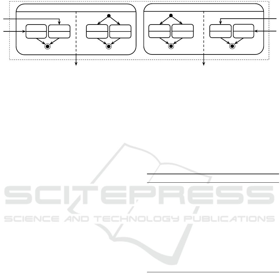
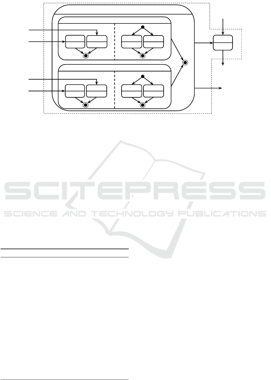
Figure 6: PSM
Disabling
of the CTT “TV”. Note that the in set contains both ingoing transitions of the compound state and
transitions of PSM
β
to bypass the execution.
and switches to another execution branch.
To finish the execution of α without interruption, the
compound state representing α is equipped with an in-
ternal final state, which is entered when α (i.e. PSM
α
)
was successfully executed. Due to the corresponding
completion transition, the compound state is automat-
ically left when α (PSM
α
respectively) was executed
without interruption of β (PSM
β
respectively).
The formal translation steps of the Disabling op-
erator are shown by Algorithm 4. Again, we ap-
ply the algorithm to the example of Figure 1. Be-
cause Disabling is the top-most operator, applying the
algorithm completely translates our CTT. α in this
case is the subtree “Operate TV” and β is the sub-
tree “Standby”. As usual, PSM
α
and PSM
β
are gener-
Algorithm 4: translate(Disabling(α, β)).
PSM
α
← translate(α)
PSM
β
← translate(α)
PSM
α
f inal
← CreateFinalStates(PSM
α
)
transitions
α
← all transitions from in(PSM
α
f inal
)
transitions
β
← all transitions from in(PSM
β
)
transitions
dup
β
← copy of transitions
β
with target
C ← CompoundState(cname, states(PSM
α
f inal
))
intermediate ←
/
0
for all i ∈ in(PSM
β
) do
C
connect
−→ i
if state was created then
intermediate ← intermediate ∪ {state}
end if
end for
t
completion
← Transition(“done.state.cname”)
C
connect
−→ t
completion
intermediate ← intermediate ∪ {t
completion
}
return PSM container PSM
Disabling
ated by applying translate to the corresponding sub-
CTTs. Next, we create the compound state for PSM
α
,
which requires an additional final state that is con-
nected to the out set (i.e. the transitions t
completion
1
and
t
completion
2
) of PSM
α
. This results in a new partial state
machine PSM
α
f inal
.
Before wrapping PSM
α
f inal
into the compound
state, the ingoing transitions “Press Chan+ But-
ton”, “Press Chan- Button”, “Press Vol+ Button” and
“Press Vol- Button” of in(PSM
α
f inal
) must be pre-
served for subsequent connections. Consequently,
the transitions of both in(PSM
α
f inal
) and in(PSM
β
)
are extracted and the transitions of in(PSM
β
) (“Press
Standby Button”) are duplicated to provide Connecta-
bles that can bypass PSM
α
and its corresponding
compound state completely.
As in set of the resulting container PSM
Disabling
,
the extracted transitions of PSM
α
and the duplicated
ingoing transitions of PSM
β
are returned. The out set
consists of the completion transition t
completion
and the
out set of PSM
β
. Consequently, the translated Dis-
abling operator of the TV example is shown in Figure
6. Note that the transitions belonging to PSM
α
point
into the compound state and not just to it.
With the root operator of the CTT translated, we
obtained a complete (yet partial) state machine from
the CTT. However, this PSM is not executable yet, be-
cause it lacks proper initial and final states. By adding
a common initial state, which is connected to the tran-
sitions of the PSM
Disabling
’s in set and a common final
state, which is connected with PSM
Disabling
’s out set,
we obtain a state machine which can be executed by
standard state machine frameworks. We call this final
step the creation of the “execution closure”.
Translating Task Models to State Machines
207

5 RELATED WORK
Task models have been found to be widely adapted in
the research community. Several related work cov-
ers the translation of task models into correspond-
ing UML diagrams, but in a limited way. For exam-
ple, (Luyten and Clerckx, 2003; Van Den Bergh and
Coninx, 2007) define mappings from CTTs to state
machines, but neither provide a formal set of rules
nor do they cover the full recursive case. Other work
maps CTTs to UML activity diagrams in a similar
way as in this work (Br
¨
uning et al., 2008; Br
¨
uning
et al., 2012). However, we feel that state charts are
easier to handle and use in actual implementations.
Furthermore, (Zhu et al., 2012) extract state ma-
chines from CTTs to derive the system behavior. Un-
fortunately, they only use it for verification, but do
not consider interactive execution. A recursive algo-
rithm to map CTTs to state machines is presented in
(Sinnig et al., 2013), but this only aims at extracting
possible executions for verifications, and also does
not consider interactive execution. Compared to this
work, related projects that employ (CTT) task models
to derive system information mostly seem to concen-
trate on the user interface (which is not enough when
focusing a more comprehensive approach to model-
driven systems engineering) or they generate UML
models on a higher and more abstract level, which re-
quire some manual effort to implement.
6 CONCLUSION
In this work, we have presented the first recursive al-
gorithm to translate CTTs, based on their tree struc-
ture, into executable state machines. Compared to
prior work, the generated state machines interact with
the environment by means of high-level events which
correspond to tasks in CTTs. These events can be
triggered by actual UI elements or concrete (sensor)
events in real implementations. A full tool chain for
this is presented in (Wagner, 2015). As the major
technical contribution of this paper, we have intro-
duced and extensively used incomplete or partial state
machines. These are composed in a recursive way
to form bigger and more complex (partial) state ma-
chines, which can act as central controllers for desk-
top or embedded applications.
REFERENCES
Br
¨
uning, J., Dittmar, A., Forbrig, P., and Reichart, D.
(2008). Getting SW engineers on board: Task mod-
elling with activity diagrams. Lecture Notes in Com-
puter Science (including subseries Lecture Notes in
Artificial Intelligence and Lecture Notes in Bioinfor-
matics), 4940 LNCS:175–192.
Br
¨
uning, J., Kunert, M., and Lantow, B. (2012). Modeling
and executing concurtasktrees using a uml and soil-
based metamodel. In Proceedings of the 12th Work-
shop on OCL and Textual Modelling, OCL ’12, pages
43–48, New York, NY, USA. ACM.
Eshuis, R. (2009). Reconciling statechart semantics. Sci-
ence of Computer Programming, 74(3):65–99.
Harel, D. (1987). Statecharts: a visual formalism for com-
plex systems. Science of Computer Programming,
8(3):231–274.
Luyten, K. and Clerckx, T. (2003). Derivation of a dialog
model from a task model by activity chain extraction.
Interactive Systems. Design . . . , pages 203–217.
Omg (2004). UML 2.4.1 Superstructure Specification. Oc-
tober, 02(August):1–786.
Patern
`
o, F. (2000). Model-Based Design and Evaluation of
Interactive Applications. Springer-Verlag London.
Patern
`
o, F. (2001). Task models in interactive software sys-
tems. Handbook of software engineering & knowl-
edge engineering, pages 817–836.
Patern
`
o, F., Santoro, C., and Spano, L. D. (2012). Concur
Task Trees (CTT).
Pnueli, A. and Shalev, M. (1991). What is in a step: On the
semantics of statecharts. 937:244–264.
Sinnig, D., Chalin, P., and Khendek, F. (2013). Use case
and task models: an integrated development method-
ology and its formal foundation. ACM Transactions
on Software Engineering and Methodology (TOSEM),
22(3):27.
Van Den Bergh, J. and Coninx, K. (2007). From Task to
Dialog Model in the UML. In Task Models and Dia-
grams for User Interface Design, pages 98 – 111.
Wagner, A. (2015). Multi-Device Extensions for CTT Dia-
grams and their Use in a Model-based Tool Chain for
the Internet of Things. Master’s thesis, TU M
¨
unchen,
Germany.
Zhu, B., Zhang, S., and Wang, A. (2012). Towards a for-
mal integrated model for function and user interface.
Proceedings - 13th ACIS International Conference
on Software Engineering, Artificial Intelligence, Net-
working, and Parallel/Distributed Computing, SNPD
2012, pages 275–280.
MODELSWARD 2016 - 4th International Conference on Model-Driven Engineering and Software Development
208
