
A Methodology for Deriving Conceptual Data Models from Systems
Engineering Artefacts
Christian Hennig
1
, Harald Eisenmann
1
, Alexander Viehl
2
and Oliver Bringmann
3
1
Space Systems, Airbus Defence and Space, Friedrichshafen, Germany
2
Intelligent Systems and Production Engineering, FZI Research Center for Information Technology, Karlsruhe, Germany
3
Wilhelm-Schickard-Institute for Computer Science, Eberhard-Karls-University of Tübingen, Tübingen, Germany
Keywords: Model-based Systems Engineering, Conceptual Data Modeling, Modeling Methodology, FBM,
Model-based Development.
Abstract: This paper presents a novel methodology for deriving Conceptual Data Models in the scope of Model-based
Systems Engineering. Based on an assessment of currently employed methodologies, substantial limitations
of the state of the art are identified. Consequently, a new methodology, overcoming present shortcomings, is
elaborated, containing detailed and prescriptive guidelines for deriving conceptual data models used for rep-
resenting engineering data in a multi-disciplinary design process. For highlighting the applicability and ben-
efits of the approach, the derivation of a semantically strong conceptual data model in the context of Model-
based Space Systems Engineering is presented as a case study.
INTRODUCTION
1.1 The Practice of Systems
Engineering
In many industrial engineering projects today, a mul-
titude of disciplines is involved in building a product.
For space projects such as satellites, launch vehicles,
and re-supply spacecraft these disciplines involve,
only to name a few, mechanical engineering, electri-
cal engineering, thermal engineering, requirements
engineering, software engineering, verification engi-
neering, and their respective sub-disciplines. Each of
these disciplines specifies their designs and verifies
specific aspects of the system. In order to provide an
all-encompassing understanding of the system of in-
terest, the unique, yet complementary, views from
every involved discipline are combined. The science
and art of integrating different views on one system
towards system thinking is called Systems Engineer-
ing. As NASA (2007) elegantly puts it: “Systems en-
gineering is a holistic, integrative discipline, wherein
the contributions of structural engineers, electrical en-
gineers, mechanism designers, power engineers, hu-
man factors engineers, and many more disciplines are
evaluated and balanced, one against an-other, to pro-
duce a coherent whole that is not dominated by the
perspective of a single discipline.”
1.2 Employment of Models in Systems
Engineering
Many of the engineering activities performed inside
these domains are already well supported by com-
puter-based models. Mechanical design models built
with tools such as CATIA V5, mechanical analysis
models built with tools such as PATRAN and thermal
analysis models built with tools such as ESATAN-
TMS are well established in the space engineering
community today. Furthermore, requirements models
based on DOORS, software design models specified
in the Ecore language using the Eclipse Modeling
Framework, as well as mission design models speci-
fied in SysML (OMG, 2015) play important roles.
Furthermore, “traditional” tools such as Excel or Vi-
sio are used on a regular basis for specifying models.
These tools and the models they produce differ
significantly from each other. They are provided by
different vendors, rely on different implementation
technologies and are based on different formats
(Kogalovsky and Kalinichenko, 2009). Each model
and the associated design methodology follow their
own principles and paradigms and define their very
own semantics. As a result of this heterogeneity, these
models and tools are not yet comprehensively inte-
grated and interconnected with each other and with
the multi-domain systems engineering process
Hennig, C., Eisenmann, H., Viehl, A. and Bringmann, O.
A Methodology for Deriving Conceptual Data Models from Systems Engineering Artefacts.
DOI: 10.5220/0005676604970508
In Proceedings of the 4th International Conference on Model-Driven Engineering and Software Development (MODELSWARD 2016), pages 497-508
ISBN: 978-989-758-168-7
Copyright
c
2016 by SCITEPRESS – Science and Technology Publications, Lda. All rights reserved
497
(INCOSE, 2014). For a truly multidisciplinary repre-
sentation of a system, relevant aspects from all in-
volved domains and their models need to be com-
bined on the model level (Eisenmann, 2012).
1.3 Describing System-wide Models
in MBSE
For overcoming these inhibitors, one approach that
can be pursued is the provision of a centralized sys-
tem database that defines a set of system-wide seman-
tics. In this architecture the system model acts as a
central hub into which discipline-specific models can
integrate information of system-wide relevance. For
defining the concepts that make up the system of in-
terest, a Conceptual Data Model (CDM) is employed.
It provides a common, resilient, and comprehensive
definition of engineering data, incorporating disci-
pline-specific as well as system-level aspects.
The approach of integrating these discipline-spe-
cific models towards a uniform system model is
called Model-based Systems Engineering (MBSE).
While the system model, or user model, repre-
sents the level where the end-user, i.e. the engineer
designing the system, performs his tasks, the CDM or
data model defines the concepts contained in the user
model and acts as the user model’s meta-model.
(Hong and Maryanski, 1990). It is worthy to note that
meta-model is a relative term. It describes concepts
one abstraction level above the model that is currently
the focus of interest. The CDM serves as an ontology
exactly defining the engineering data of interest,
plays an important role when communicating about
this data, and forms the entry-point for software engi-
neering activities that implement an engineering ap-
plication supporting the system design process. The
conceptual data model can be seen as the back-bone
of MBSE (ESA, 2011).
A variety of approaches exist for building such
models. On the one hand there are approaches
strongly driven by the implementation technologies
that are used for producing engineering applications,
relying on data models specified in UML or Ecore.
On the other hand there are techniques that are highly
focused on representing knowledge, such as the Web
Ontology Language OWL or Fact Based Modeling
FBM, but are not meant for describing pieces of soft-
ware.
The relation of discipline-specific models, system
mode, CDM, and data modeling language is visual-
ized in
Figure 1.
For producing CDMs in this context, the techno-
logical aspect is not the only point of concern. Meth-
odologies for developing software and models have
Figure 1: Relation of domain models, system model, CDM,
and data modeling language.
gained traction, with the aim of moving the develop-
ment from an art into an engineering discipline with
traceable, reproducible, and validatable results. For
the software-driven languages, methodologies exist
that help in developing the data model, e.g. by provid-
ing guidelines on how to structure the data model, or
how to validate it. For the knowledge-based ap-
proaches methodologies also exist that help in deriv-
ing a CDM for an intended use case. While each of
the existing methodologies has its characteristic mer-
its, currently no methodology is suited for producing
CDMs in the context of MBSE.
1.4 Paper Objective and Outline
Consequently a methodology is detailed that fits the
requirements arising in the scope of interdisciplinary
knowledge integration in MBSE. This methodology
uses an engineering process and its process artefacts
as a point of origin for deriving the CDM that is in-
tended to support engineering activities. By following
the procedures prescribed by the methodology, facts
are generated in order to explore all possible con-
straints and add them to the model if required. This
approach leads to a quasi-standardized, virtually ex-
haustive model, given the initially provided facts
were correct. After the model or parts of it have been
completed it is validated through the provision of
sample facts taken from the original source.
In the following sections industrial requirements
for a methodology suited for producing CDMs in
MBSE are identified. Consequently a brief examina-
tion regarding how well each of the analyzed meth-
odologies is able to cope with the requirements is
given. Based on this examination a novel methodol-
ogy is presented that brings together the advantageous
features of the existing approaches. For demonstrat-
ing the methodology’s utility a sample CDM is devel-
oped, demonstrating the CDM design cycle in gen-
eral, highlighting some of its aspects in detail.
System Model
Mechanical
Engineeri ng
Requirements Engineering
DOORS
Requirements
Rep ository
PATRAN
Analysis
Model
Mission Design
STK
Orbit
Model
SysML
Mission
Model
Simulator
Engineeri ng
MATLAB
Analysis
Model
Conceptual Data Model
Data Modeling Language
Cus tom
Simulato r
Model
Modelica
Analysis
Model
Excel
Mass
Bu dget
CATIA
CAD
Model
MODELSWARD 2016 - 4th International Conference on Model-Driven Engineering and Software Development
498

2 STATE OF THE ART
REGARDING
METHODOLOGIES
2.1 Methodologies Employed
for Developing CDMs
For producing CDMs, a variety of methodological ap-
proaches are applied in practice. These approaches
come from a variety of application domains.
2.1.1 Software-Driven Approaches
Established approaches and methodologies related to
classic software design, such as the Waterfall Model,
the V-Model, or the Spiral Model focus a lot on the
overall approach, and not on detailed design aspects
of the software to be developed. Approaches that em-
phasize on the detailed, structured, and guided design
of the conceptual data model underlying the software
are scarce and hardly applicable to the MBSE use
case. Consequently, the “classical” methodologies
from the software engineering domain have been ex-
cluded in the remainder of this paper.
2.1.2 Requirement-Driven Approaches
For software developments that rely heavily on pro-
ducing a sensible data model, the approach of exten-
sive data model specification and subsequent valida-
tion is pursued, for instance in the EGS-CC project
(ESA, 2013). In this approach requirements on the
CDM are formulated that exactly specify what con-
tents it shall have, how the contents relate, what func-
tionalities have to be provided, etc. After the CDM is
produced a mix between verification and validation is
performed by instantiating the CDM, producing sam-
ple populations, and checking if the data specified in
the requirements can be represented accurately and
completely.
2.1.3 Approaches from the Ontology World
In the domain of ontology engineering, emphasis is fre-
quently put on a methodological approach to designing
and maintaining an ontology, for transforming work-
ing on knowledge “from an art into an engineering
discipline.” (Studer, et al., 1998) A variety of meth-
odologies in this context have been proposed through
the years, such as METHONGOLOGY (Fernández,
et al., 1997), OTKM (Sure, et al., 2004), or the NeOn
Methodology (Suárez-Figueroa, 2010).
Many of these methodologies discuss aspects
such as ontology management activities, ontology de-
velopment activities, and ontology support activities.
However, in many cases, these aspects are only pro-
posed or outlined in the methodology, and not de-
scribed in detail (Gómez-Pérez, et al., 2004).
2.1.4 Approaches from Fact based Modeling
The field of Fact Based Modeling also relies heavily
on modeling methodologies. For producing data
models in Fact Based Modeling languages such as
ORM2 (Halpin and Morgan, 2008), methodologies
such as NIAM (Leung and Nijssen, 1998), CogNIAM
(CogNIAM.eu, 2015), or CSDP (Halpin and Morgan,
2008) are employed. These approaches all rely on the
formulation of elementary facts (Halpin and Morgan,
2008) and employ these for developing CDMs in a
bottom-up, example-driven scenario.
2.2 Requirements on a Methodology
for Designing CDMs in MBSE
In order to produce CDMs that can be employed effec-
tively in MBSE, several requirements have been iden-
tified for a modeling methodology. These requirements
are based upon extensive experience in projects that in-
corporate CDMs as central elements (ESA, 2013),
(ESA, 2012), (Fischer, et al., 2014). In the scope of this
paper only an overview of the needs for a conceptual
data modeling methodology can be given, highlighting
the most important points. These requirements have
been partitioned into four categories.
2.2.1 Support for CDM Specification
Activities
The methodology should offer guidelines for specify-
ing the CDM. This can include either a classic speci-
fication of the CDM to be designed through require-
ments, or an approach where the engineering process,
which the CDM will be designed for, together with its
process artefacts, is used as an entry point.
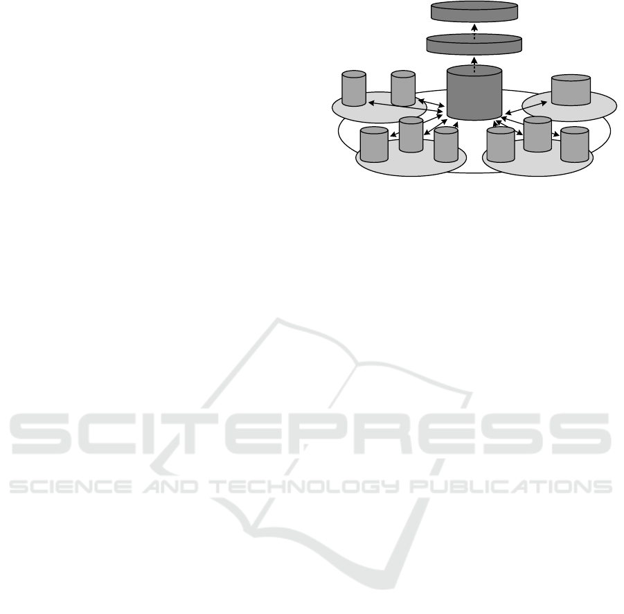
In the MBSE approach, a CDM bridges the gap
between the abstracted PDM world that is used to
manage the complexity and coordination of disci-
pline-specific engineering activities on the one hand,
and the detailed data that is being produced in the dis-
cipline-specific engineering activities on the other
hand (Hennig and Eisenmann, 2014). While the item
that is managed in the PDM world is of a very abstract
nature, the item may be handled by a number of do-
mains in entirely different representations. The pur-
pose of the CDM is to connect both worlds, assuring
A Methodology for Deriving Conceptual Data Models from Systems Engineering Artefacts
499
the correct mapping between detailed data and ab-
stracted artefacts. This is illustrated in Figure 2.
Figure 2: Relation of PDM, CDM, and Engineering
Domains.
For ensuring the CDM’s compatibility to do so, both
the PDM representation of artefacts and the detailed
specification of data has to be considered and serve as
the point of origin for deriving the CDM.
2.2.2 Support for CDM Design Activities
For pursuing the design of the CDM the initial step is
to acquire knowledge, e.g. from documentation, from
interviews with domain experts, or from combina-
tions of both. After knowledge is acquired, the
CDM’s data structures such as classes, attributes, ref-
erences, and data types can be derived from the pre-
viously acquired knowledge. Constraints can also be
derived from the acquired knowledge and are usually
modeled after the main structure of the CDM has been
designed. A methodology should include detailed in-
structions for all three activities.
2.2.3 Support for CDM Verification
and Validation Activities
In order to ensure that the CDM is built according to
its specifications and that it is able to fulfil its in-
tended purpose some kind of control mechanism has
to be in place. This implies, based on the design of the
methodology’s specification activities, that it should
support formal requirements verification, e.g. through
the definition of test cases, some kind of validation
through the provision of sample instances, or both. In
the latter, the CDM has to be instantiated for provid-
ing the means of entering data. The CDM is valid if
the data can be entered in a way identical or at least
very similar to the original source, i.e. the knowledge
acquired for deriving the CDM.
2.2.4 CDM Support Activities
Besides formal specification, design, and V&V activ-
ities, other aspects are also to be considered in a con-
ceptual data modeling methodology. For ensuring a
somehow standardized structure of models built ac-
cording to the methodology, the provision of naming
conventions is an important factor. Furthermore
guidelines of how to integrate different CDMs with
each other are an important asset. Another essential
part of any design activity is effective and efficient
configuration management, so guidelines for such ac-
tivities should also be included.
2.3 Evaluation of Conceptual Data
Modeling Methodologies
For more detailed evaluation several approaches are
selected from those outlined in 0. From the ontology
world the NeOn Methodology is chosen since it is one
of the more recent ones and can be seen as an ad-
vancement to methodologies like OTKM (Sure, et al.,
2004) or METHONTOLOGY (Fernández, et al.,
1997). The requirements-driven methodology from
the EGS-CC project (ESA, 2013) has been selected as
an analysis candidate because it is the most recent ap-
proach in this context. From the field of Fact Based
Modeling, CSDP (Halpin and Morgan, 2008) and the
CogNIAM Protocol (CogNIAM.eu, 2015) have been
selected. Although the latter are two distinct method-
ologies they rely on largely the same principles, albeit
with different nuances. While the CSDP is rather de-
scriptive, CogNIAM achieves similar goals in a very
prescriptive way.
2.3.1 Definition of Evaluation Scheme
A detailed evaluation of selected methodologies,
based upon weighted score evaluation according to
requirements that arise in the context of MBSE, has
been performed but is not elaborated due to length
constraints of this paper. Instead, the most important
results in terms of qualitative features are outlined in
the following sections.
2.3.2 Evaluation of the NeOn Methodology
The NeOn Methodology puts an emphasis on speci-
fying ontology requirements. Processes and process
artefacts are not considered in its scope. Regarding
design activities the methodology offers general
guidelines, but no specific instructions. This is also
true for the validation and verification activities. It
mentions naming conventions as an important aspect
but does not offer specific guidelines, the same is true
Product Data Management
CDM
Engineering
Domain
Engineering
Domain
Engineering
Domain
Process Artefact
Internal Representation
Ex te rnal Repre sentati on
MODELSWARD 2016 - 4th International Conference on Model-Driven Engineering and Software Development
500

for configuration management. The aspect of inte-
grating different ontologies is well considered how-
ever.
+ Ontology integration well elaborated
− No consideration of processes and process arte-
facts
− Insufficient consideration of design activities
− Insufficient consideration of V&V activities
2.3.3 Evaluation of Requirements-Driven
Methodology
The requirements-driven approach applied in EGS-
CC puts significant emphasis on a thorough specifi-
cation of the CDM. However, extensive design and
support activities are currently not part of the meth-
odology. For V&V activities a mix of formal require-
ments verification and validation through sample in-
stances is performed. Configuration management is
an essential part of the methodology, following a tra-
ditional approach of frequently producing revisions
that are then released at specific milestones.
+ Thorough emphasis on requirements modeling
+ Thorough emphasis on validation and verifica-
tion
+ Consideration of configuration management
− No consideration of other support activities
− No consideration of processes and process arte-
facts
− Virtually no consideration of design aspects
2.3.4 Evaluation of CSDP and CogNIAM
CSDP and CogNIAM do not consider specification
activities since the point of origin is acquiring
knowledge through the formulation of elementary
facts. However, data structure and constraint model-
ing are extremely well detailed in both methodolo-
gies, although with somehow different emphasis.
Validation is performed through the provision of sam-
ple instances. Naming conventions also play an inher-
ent role.
+ Knowledge acquisition integral part
+ Highly detailed modeling instructions given
− No consideration of other support activities
− No consideration of processes and process arte-
facts
2.3.5 Conclusion of Evaluation
The evaluation makes evident that there currently is
no methodology that caters to all requirements formu-
lated for producing CDMs in the context of MBSE.
Each of the methodologies exhibits shortcomings in
one of the main categories. Furthermore, the aspect of
incorporating an engineering process or process arte-
facts into the CDM development process is not ad-
dressed anywhere.
3 METHODOLOGY DESIGN
As a consequence of the analysis, a new methodology
is proposed that picks up on characteristic features of
the examined candidates. It is inspired by the
knowledge-acquisition and design activities of CSDP
(Halpin and Morgan, 2008) and CogNIAM
(CogNIAM.eu, 2015), while picking up on configu-
ration management and validation aspects from the
requirements-based approach and integration aspects
from the NeOn Methodology (Suárez-Figueroa,
2010). The consideration of processes and process ar-
tefacts has been developed from scratch.
3.1 General Methodology Principles
3.1.1 Engineering Processes as a Point
of Origin
The starting point for employing the methodology is
the engineering process that will have its data de-
scribed in the CDM. From a PLM point of view the
engineering process uses artefacts that serve as inputs
and outputs of activities. When detailed from the per-
spective of an actual engineering activity that details
the PLM-managed activity with engineering tasks, a
detailed description of the artefacts is required. This
detailed description is the actual, detailed engineering
data that is exchanged between different engineering
domains. This level makes visible what data is re-
quired by several engineering tasks, making it a mod-
eling candidate for the CDM that represents the Sys-
tem Model.
3.1.2 Using Elementary Facts about the UoD
for Acquiring Knowledge
Originating from the artefact used in the engineering
process the data model is derived. These knowledge
acquisition activities rely on deriving elementary
facts from the artefact documentation, using familiar
examples to drive the CDM.
Basically, an elementary fact is an assertion that
one object is playing one specific role (Halpin and
Morgan, 2008). The most basic elementary fact is that
one entity plays one independent role, such as “Grav-
itySat flies.” Most of the time relationships involve
A Methodology for Deriving Conceptual Data Models from Systems Engineering Artefacts
501
two roles, such as “GravitySat is launched by Ariane
5”. Basically an elementary fact “asserts that a partic-
ular object has a property, or that one or more objects
participate together in a relationship.” (Halpin and
Morgan, 2008). The word elementary indicates that
the fact cannot be split into smaller units of infor-
mation that collectively provide the same information
as the original.
Elementary facts usually do not use logical con-
nectives such as NOT, AND, OR, IF, or logical quan-
tities such as SOME or ALL. Elementary facts can be
made up of several building blocks:
Entities are particular things, e.g. a particular
organization such as ESA, a particular object
such as Launch Pad, or a particular person,
such as Angela Merkel.
Values are constants that provide some kind of
identification once the context is known. Val-
ues can be numbers, such as 3, 36 or 77, but
also character strings such as “Germany”,
“EU”, or “MODELSWARD”.
Predicates connect entities with other entities
or values by putting them into a declarative
statement. Predicates can be unary (specifying
one entity), binary (two entities or an entity and
a value), ternary, and in theory n-ary. Predi-
cates may have two reading directions with dif-
ferent meaning, such as “GravitySat is
launched from Kourou” and “Kourou is launch
site for GravitySat”.
3.1.3 Language Support
for the Methodology
This kind of methodology for deriving CDMs from
example data formulated as elementary facts is suited
for producing models with Fact Based Modeling lan-
guages. The methodology has been developed in par-
allel to a conceptual data modeling language called
SCDML (Hennig, et al., 2016), currently being the
only solution that ensures full compatibility of lan-
guage and methodology. SCDML is a conceptual data
modeling language that is currently under develop-
ment and can be seen as the unification of a produc-
tion-oriented data modeling language (Ecore) with a
conceptual modeling language (ORM), with the addi-
tion of other extensions, such as elements for process
modeling.
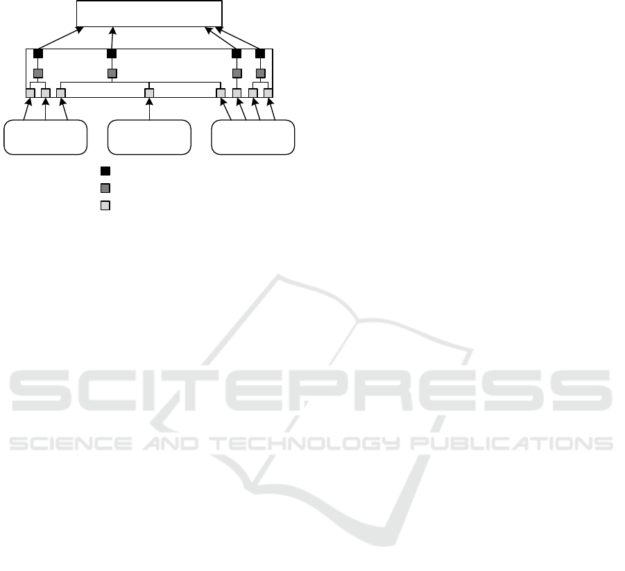
3.1.4 Methodology Decomposition
The methodology is composed of several levels (Fig-
ure 3), similar to those described by Gómez-Pérez, et
al. (2004). It is composed of a variety of processes,
represented by those numbered 1 to 8 in
Figure 4.
These are decomposed of several activities. Some of
those activities are further decomposed into tasks,
which represent the methodology’s smallest kind of
step.
Figure 3: Decomposition of SCDML Methodology.
The methodology is based upon the principle that the
most important constraints should be derived first,
and less important constraints can be derived later on.
In general, the constraints that are treated first in the
methodology are the most important ones, such as in-
ternal uniqueness constraints and mandatory con-
straints, where the constraints considered in the
higher numbered activities are of less importance.
Figure 4: Top-level flow of processes in the SCDML
methodology.
The methodology consists of a number of steps that
contain instructions for developing a specific aspect
Process
Activities
Task
Met hodol ogy
1. Mode l Engi ne er ing
Process
2. Model Tasks
3. Classify Artefact
Representations
4. Mo de l Comple x
Representations
5. Mo de l Simple
Representations
6. Model Category
Representations
7. Specify Model Maturity
Aspects
8. Perform CDM
Verification and Validation
no
yes
yes
no
Mo de li ng of ta sks r eq ui r ed?
All identified representations modeled?
Verification and validation successful?
MODELSWARD 2016 - 4th International Conference on Model-Driven Engineering and Software Development
502

of the CDM. It follows an iterative approach. While
the engineering process and its activities may be mod-
eled or imported in one step, each artefact requires an
analysis of its representations, and, depending on the
outcome of the analysis, an iteration through one of
the different modeling processes. This is to be iterated
over every artefact of relevance. Furthermore the
SCDML methodology contains guidelines regarding
naming conventions, configuration management and
integration of other sources of knowledge.
METHODOLOGY
APPLICATION
Instead of detailing the SCDML methodology in a
theoretical manner with a brief validation thereafter,
the detailed steps of the methodology will be ex-
plained via example. The example detailed in this sec-
tion demonstrates the utility of the methodology for
producing CDMs in the context of MBSE.
4.1 Modeling of ESA System
Engineering Process
As a sample process to be modeled the ESA System
Engineering Process as defined in ECSS-E-ST-10C
(ESA, 2009) is chosen. This document, among other
things, specifies what systems engineering artefacts
are required at specific points of time in the design
cycle of a spacecraft developed in the scope of an
ESA project.
Initially the methodology proposes the modeling
of the engineering process that the CDM is supposed
to support. As a first step the process itself is to be
specified, followed by the specification of activities
and control elements as a second step. As a third step
the input and output artefacts of the process activities
should be specified in the model. The methodology
refrains from detailing the activities with tasks, since
process modeling is already well established through
existing methodologies.
In case of ECSS-E-ST-10C the process descrip-
tion is rather high level. In essence, the ESA System
Engineering Process is decomposed of a number of
sub-processes that each represent one phase of the en-
gineering cycle with one review at the end of each
phase and at times further reviews inside one phase.
Reviews are normal process elements that can have
input and output artefacts. In the case of the process
in question all of the artefacts serve as input for one
or several reviews. One critical artefact in space
system engineering is the Product Tree (
Figure 6
). It
contains the decomposition of the spacecraft to be
developed, and will be detailed with a data model
later on.
4.2 Modeling of Tasks
The second methodology step of modeling the tasks
of the engineering activities is not pursued in the case
at hand. These activities are not detailed in the ECSS-
E-ST-10C standard and the step is specified as
optional.
4.3 Classification of Artefact
Representations
The next step of the methodology is to determine the
concrete nature of the artefact.
An external representation describes that data
about this artefact is defined somewhere in an engi-
neering tool other than the tool that currently is to be
developed. External representations of artefacts can
be mapped to one of the internal representations via a
model transformation, an import process, or a similar
data integration approach, enabling the application
implementing the CDM to serve as a central, integra-
tive hub for engineering data.
Simple representations are descriptions of process
artefacts that have to be visible somehow in the engi-
neering process, but do not have to be highly detailed.
Simple representations only consist of one Entity
Type with few Value Fact Types. Examples would be
specifications, reports, or manuals that have more
documental value than real value for systems engi-
neering. In general, simple representations should be
used for artefacts where the artefact is managed in the
systems engineering activities, but not the detailed
data underlying the artefact. Due to the reduced com-
plexity involved in modeling simple artefacts in com-
parison to complex artefacts, only the latter will be
detailed in this paper.
Complex artefacts are central elements of the sys-
tem engineering process where concrete access to the
underlying data is required. This includes require-
ments specifications where discrete access to the con-
tents of requirements and their traces is needed, spec-
ifications of electrical architectures, the functional ar-
chitecture of a system, etc.
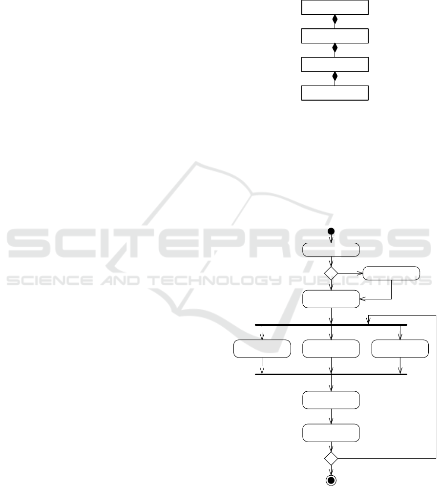
The Product Tree is a complex artefact with four
external representations. It contains critical infor-
mation about the system decomposition, such as
names and abbreviations of system elements, system
element hierarchies, etc. that are of central relevance
to the system engineering process. Furthermore simi-
lar structures are defined in a PDM system, and in an
A Methodology for Deriving Conceptual Data Models from Systems Engineering Artefacts
503
Excel sheet, legacy from early project phases. SysML
is gaining a lot of traction as a specification tool for
early project phases and enables the specification of a
product tree using the block-stereotype. Furthermore
CAD tools such as CATIA also rely heavily on an in-
ternal product structure (
Figure 5
).
Figure 5: Representations of Product Tree artefact.
4.4 Modeling of Complex Artefacts
Now that the rough nature of the artefact has been
specfied, it needs to be modeled in detail. The first
step to begin modeling a complex artefact is to create
a package in which the artefact will be elaborated.
This will ensure that all Entity Types, Value Types
and Fact Types pertaining to the artefact will be
grouped together and easily traceable.
Figure 6: Excerpt from a product tree of a sample project.
A more detailed description definition of Entity
Types, Fact Types, etc. can be found at Halpin &
Morgan (2008). For the derivation of the data structure
of the artefact, an example is used. In this case the
example is the Excel Product Tree, as employed in
early project phases, outlined in Figure 6.
As an initial step for acquiring the required
knowledge some fact about the data at hand is formu-
lated. For cross-checking and for later modeling ac-
tivities, several facts are required.
The Battery is abbreviated by BAT.
The Data Handling System is abbreviated by DHS.
The On-Board Computer is abbreviated by OBC.
After acquiring a number of basic facts, the fact
structure can be determined. For this purpose the con-
stant and variable parts of the fact are identified.
The Battery is abbreviated by BAT.
The Data Handling System is abbreviated by DHS.
The On-Board Computer is abbreviated by OBC.
<variable part> <constant part> <variable
part>
Now the question of what the variable parts rep-
resent has to be answered. The objects on the left side
are all Product Tree Elements. The objects on the
right side are Abbreviations. Variable parts of facts
denote entities, more specifically they represent one
Entity Type. If the variable part is more of an addi-
tional information to an Entity Type, it is a Value
Type. The constant parts of a fact represent a predi-
cate. Consequently these facts can be abstracted to a
Binary Fact Type (because it is relating two Object
Types) that reads
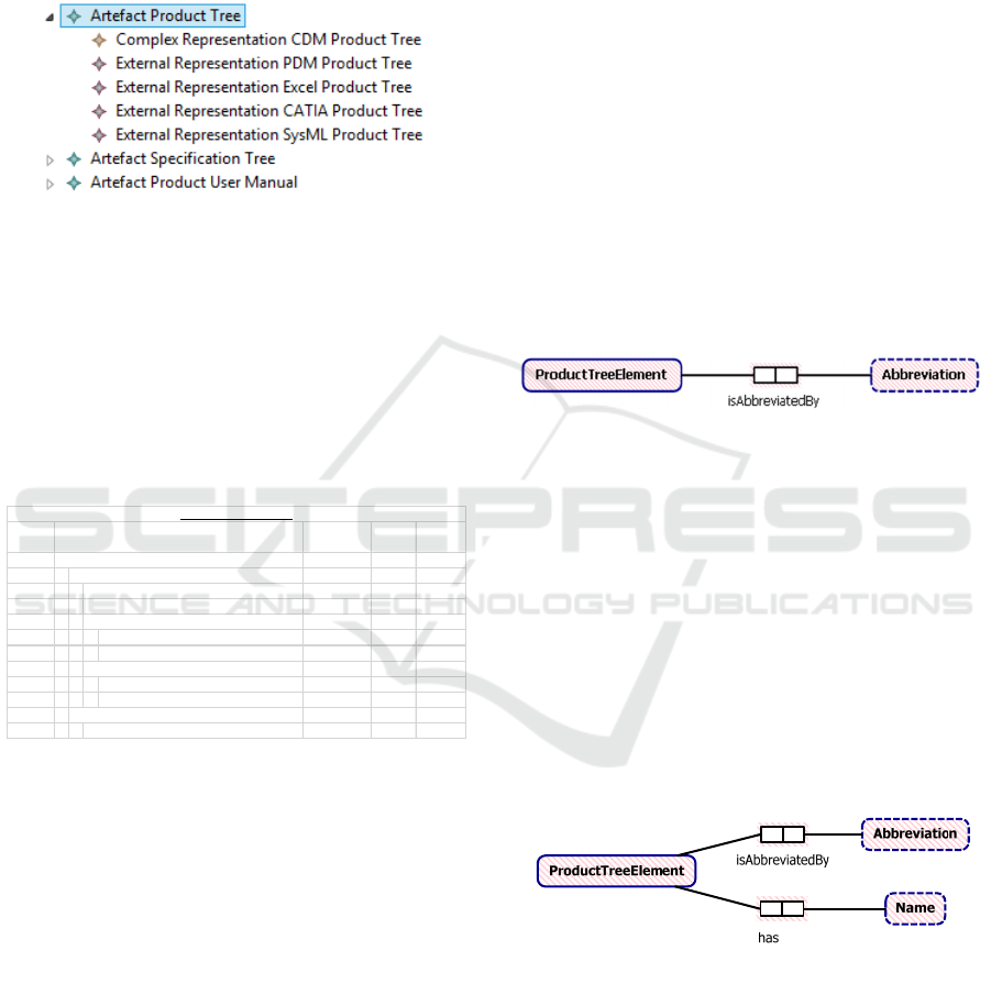
Product Tree Element is abbreviated by Abbreviation.
This derived data structure can then be asserted to
the CDM using the ORM2 syntax (Halpin & Morgan,
2008) (
Figure 7
).
Figure 7: ProductTreeElement and Abbreviation.
Currently the Product Tree Element only has an
explicitly modeled Abbreviation, and not a name. The
name of the element is implicitly given in
Figure 6
and
is derived using the same algorithm as above (
Figure
8
). Each Entity Type, in this case the ProductTreeEl-
ement, requires a description that specifies what it
represents, such as “A Product Tree Element is the
description of a system element that describes the hi-
erarchical decomposition of a system. These elements
make up the product tree.”
Furthermore, Value Types need to have their data
type set. In this case, Abbreviation and Name are both
fields of text, so the data type of choice is String.
Figure 8: Addition of has Name fact type to CDM.
The next steps of the methodology are about the
derivation of model constraints. The most important
constraints to be derived are uniqueness constraints.
The fact types at hand are both binary fact types for
which an algorithm can be used in order to derive
their internal uniqueness constraints.
As a first step a reference fact (RF) is written
down. Second, another “artificial fact” is created
Config
Item No. Abbreviation
is
Abstract
No. of
Elements
0000 GravitySat GravitySat 0 1
1000 Ele ctrical Powe r System EPS 1 1
1100 Power Control and Distri bution Unit PCDU 0 1
1200 Battery BAT 0 1
1310 Solar Array +Y SAPY 1 1
1311 Sol ar Array +Y A ft Panel SAPYA 0 1
1312 Sol ar Array +Y Bow Pane l SAPYB 0 1
1320 Solar Array -Y SAMY 1 1
1321 Sol ar Array -Y Aft Panel SAMYA 0 1
1322 Sol ar Array -Y Bow Panel SAMYB 0 1
2000 Data Handling System DHS 1 1
2100 On-Board Computer OBC 0 1
GravitySat Product Tree
Product Tree Element
MODELSWARD 2016 - 4th International Conference on Model-Driven Engineering and Software Development
504

where the left variable part is changed (F1) and an-
other “artificial” fact is written down where the right
variable part is changed (F2).
RF: The On-Board Computer is abbreviated by OBC.
F1: The On-Board Computer is abbreviated by SA.
F2: The Solar Array is abbreviated by OBC.
By determining which facts can occur in the Uni-
verse of Discourse (UoD) at the same time, the unique
combinations of ProductTreeElements and Abbrevia-
tions can be derived. If RF and F2 were to occur at
the same time, that would mean that OBC can be an
Abbreviation for two distinct ProductTreeElements at
the same time. This is not to be allowed. If RF and F1
were to occur at the same time that would imply that
the On-Board Computer would have two Abbrevia-
tions at the same time, which is also to be explicitly
excluded. This means that uniqueness constraints
have to be added to the isAbbreviatedBy fact type.
Analysis of the has fact type yields the same results.
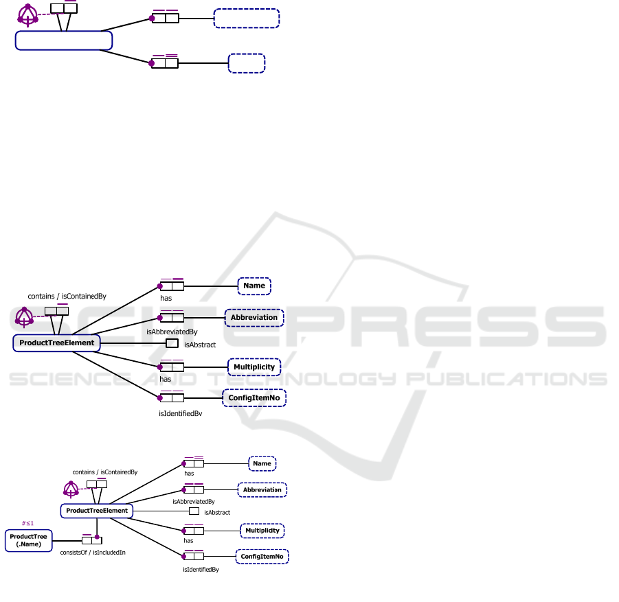
Furthermore, the Name will serve as the identification
scheme for any ProductTreeElement, which is
marked by the double uniqueness bar.
As a next step the mandatory constraints are to be
derived. For this purpose the question is asked if it is
mandatory that every ProductTreeElement has a
Name. If the answer to the question is yes, a manda-
tory constraint has to be introduced to the CDM,
which is the case in the example. The same question
is asked for the Abbreviation, yielding the same re-
sult. This yields constraints as shown in
Figure 9.
Figure 9: Derived constraints for the isAbbreviatedBy and
the hasName fact types.
On the side of the Value Types the mandatory
constraint is always implied and does not need to be
explicitly modeled.
For now no more constraints have to be derived.
Consequently, new kinds of facts can be formulated
for deriving further CDM elements.
In
Figure 6, among other things, an explicit hierar-
chy of ProductTreeElements can be observed. These
facts are analyzed in the already known manner.
The GravitySat contains the EPS.
The EPS contains the Battery.
The GravitySat contains the DHS.
<variable part> <constant part> <variable part>
ProductTreeElement contains ProductTreeElement.
After asserting this information to the model, the
question can be asked if the “inverse reading direc-
tion” is also of relevance to the UoD. This would
mean that, if the GravitySat contains the EPS, then
the EPS is contained by the GravitySat. In this case
this reading direction is identified as being in fact of
interest to engineering the system, so it is included in
the CDM.
For deriving the uniqueness constraint a reference
fact is written down and two variations are produced.
RF: The EPS contains the Battery.
F1: The EPS contains the PCDU.
F2: The DHS contains the Battery.
The reference fact is always true. RF and F1 mean
that the EPS can contain more than one Product-
TreeElement. This is also a valid constellation for the
UoD. RF together with F2 would mean that the Bat-
tery can be included by the EPS and DHS at the same
time. This is determined to be an invalid fact. Conse-
quently, a uniqueness constraint on the side of the is-
ContainedBy role is necessary, meaning it needs to be
unique.
A mandatory role constraint is not determined as
being applicable, since there might be a top-level ele-
ment that is not contained by another element, as well
as leaf elements that do not contain any other ele-
ments. Since the contains relationship denotes some
kind of hierarchy in the source document, the isCon-
tainment property is set, which states that the
ProductTreeElements connected via the contains role
form a hierarchy.
For this kind of predicate, called ring predicate,
ring constraints might also be applicable. Ring con-
straints are logical statements about what kinds of re-
lations may be possible between two entities. Consid-
ered ring constraint properties within scope of the
SCDML Methodology are reflexivity, irreflexivity,
symmetry, asymmetry, transitivity, intransitivity, and
acyclicity.
For determining the kind of ring constraint, start-
ing with a powerful one such as acyclicity is promis-
ing. Acyclicity in this case means that the contains
relation is not allowed to form any cycles. It means
that constructs such as The GravitySat contains the
EPS, the EPS contains the Battery and the Battery
contains the GravitySat are disallowed. Acyclicity al-
ready implies irreflexivity and asymmetry, which is
why these properties do not have to be considered if
the constraint is already known to be acyclic. How-
ever transitivity and intransitivity have to be evalu-
ated. Transitivity would mean that it would be al-
lowed to specify that if the GravitySat contains the
EPS and the EPS contains the Battery, then the Grav-
itySat also contains the Battery. Although this might
A Methodology for Deriving Conceptual Data Models from Systems Engineering Artefacts
505
make sense in some UoDs, in the UoD at hand this
behavior is not desired since an explicit hierarchy via
the contains role is envisioned. Consequently the ring
constraint is specified as acyclic and intransitive (
Fig-
ure 10).
Figure 10: Addition of ring constraint to contains fact type.
Properties that have a boolean characteristic are
modeled as Unary Fact Types in ORM. This is the
case for the is abstract column in
Figure 6. Unary fact
types do not have any uniqueness, mandatory, or
other constraints. Once the Value Types and Fact
Types for the ConfigItemNo and the Multiplicity have
also been modeled, all knowledge found in the
original source document has been acquired and
derived into the CDM (
Figure 11).
Figure 11: Addition of further fact types.
Figure 12: Addition of Product Tree.
For acquiring knowledge about the UoD,
documentation is not the only source that can be used.
Validation and talks with experts also serve as a
valuable source. For instance an expert could provide
the information that there is something called
ProductTree that consist of ProductTreeElements, i.e.
the ProductTreeElements are included in the
ProductTree. Using the procedures for deriving
uniqueness and mandatory role constraints yields the
following model. For entity types a check for any
object cardinality constraints is also applicable. This
includes the question “Is it possible that there exists
more than one ProductTree?”. Since the UoD expert’s
answer is “no”, an object cardinality constraint of
0..1 is to be included for the ProductTree (
Figure 12).
4.5 CDM Verification and Validation
For assuring that the CDM can actually represent the
information required for describing the artefact, a
two-step approach is pursued.
A prerequisite for this is to have an initial appli-
cation running that implements the CDM, enabling its
instantiation. In the case of the SCDML language this
would imply that the application code has been gen-
erated from the CDM. The generated application can
then be used to specify a user model.
The first step is to perform the verification activ-
ity. In this activity, the “specification” of the CDM,
i.e. the verbalized facts that have been used in the der-
ivation activities, are entered into the application.
This includes facts that should be possible in the
UoD, as well as facts that should not be possible. The
latter should either be impossible to be asserted in the
system model, or get flagged during automated model
validation since they violate some constraint. The
verification activity serves as a first, rough control if
the model has been designed according to its specifi-
cation. If a fact that has been specified cannot be as-
serted to the user model, the according part of the
CDM has to be reviewed and redesigned. In this step,
the sample facts can be seen as a specification, i.e. re-
quirements on the CDM.
The second step is the validation activity. This ac-
tivity is meant to assure that the built CDM is not only
built according to its specification, as confirmed by
the verification activity, but that the specification was
indeed correct and the CDM can correctly represent
the information it is originally intended to contain. In
other words if the CDM can accurately represent the
information from the original artefact specification,
then it is validated. If this is not possible, an analysis
has to be performed in that determines the errors and
the CDM has to be fixed. In the example this means
that the CDM must be able to accurately represent the
information from the original product tree table dis-
played in
Figure 6.
4.6 Summary
For deriving the CDM as shown in Figure 12, a subset
of 18 facts has been picked up from the source docu-
ment, the GravitySat product tree, which includes in
ProductTreeElement
Abbreviation
Name
isAbbreviatedBy
ha
s
contains / isContainedBy
MODELSWARD 2016 - 4th International Conference on Model-Driven Engineering and Software Development
506

total 314 elementary facts. Furthermore a single fact
has been provided by a discipline expert. A number
of 10 additional facts were generated by following the
proposed approach for deriving the CDM. The execu-
tion of 75 activities in total, many of which were per-
formed multiple times, resulted in the generation of
30 model elements in total (Table 1).
Table 1: Summary of pursued facts and derived data model
elements.
No. of facts stated in source document 314
No. of facts used for model derivation 18
No. of additional facts by discipline expert 1
No. of additional facts from model derivation 10
No. of activities performed 75
No. of derived fact types 7
No. of derived entity types 2
No. of derived value types 4
No. of derived constraints 17
5 CONCLUSION
Based on an analysis of existing methodologies for
conceptual data modeling and the formulation of re-
quirements, based on extensive experience with
MBSE, a new methodology has been developed. As
key points, this methodology encompasses
Using an engineering processes as point of
origin for modeling the CDM, picking up on its
process artefacts, refining them
Using a limited number of elementary facts for
acquiring knowledge about the artefact
Following a guided, prescriptive approach for
deriving the CDM, exploring every possible
area, leading to a virtually exhaustive model
Verifying the CDM through entering the de-
rived sample facts
Validating the CDM through entering the orig-
inal information from the data source
Establishing a connection between the ab-
stracted PDM process and detailed discipline-
specific engineering processes through the pro-
vision of an adequate CDM, taking into ac-
count different artefact representations
Leading to a quasi-standardized CDM.
The SCDML Methodology picks up on character-
istic merits of existing methodologies, adding the
PDM and process characteristics as novel elements,
resulting in a comprehensive approach for developing
CDMs, enabling an efficient and effective integration
of multi-disciplinary data in the context of Model-
based Systems Engineering.
REFERENCES
CogNIAM.eu, 2015. CogNIAM.eu. [Online]
Available at: http://www.cogniam.eu/
Eisenmann, H., 2012. VSD Final Presentation. [Online]
Available at: http://www.vsd-project.org/download/
presentations/VSD_P2_FP_2012-05-15_v3.pdf/
ESA, 2009. Space engineering – System engineering
general requirements. ESA Standard ECSS-E-ST-10C.
s.l.:s.n.
ESA, 2011. Space engineering - Space system data
repository. ESA Technical Memorandum ECSS-E-TM-
10-23A. s.l.:s.n.
ESA, 2012. The Virtual Spacecraft Design Project.
[Online] Available at: http://vsd.esa.int/
ESA, 2013. EGS-CC - European Ground Systems -
Common Core. [Online]
Available at: http://www.egscc.esa.int/
Fernández, M., Gómez-Pérez, A. & Juristo, N., 1997.
METHONTOLOGY: From Ontological Art Towards
Ontological Engineering, AAAI Technical Report SS-
97-06, s.l.: s.n.
Fischer, P. M., Eisenmann, H. & Fuchs, J., 2014. Functional
Verification by Simulation based on Preliminary
System Design Data. 6th International Workshop on
Systems and Concurrent Engineering for Space
Applications (SECESA), 8-10 October.
Gómez-Pérez, A., Fernández-Lopez, M. & Corcho, O.,
2004. Ontological Engineering. London: Springer.
Halpin, T. & Morgan, T., 2008. Information Modeling and
Relational Databases. 2nd ed. Burlington: Morgan
Kaufmann.
Hennig, C. & Eisenmann, H., 2014. Applying Selected
Knowledge Management Technologies and Principles
for Enabling Model-based Management of Engineering
Data in MBSE. 6th International Workshop on Systems
and Concurrent Engineering for Space Applications
(SECESA), 8-10 October.
Hennig, C. et al., 2016. SCDML: A Language for
Conceptual Data Modeling in Modle-Based Systems
Engineering. 4th International Conference on Model-
Driven Engineering and Software Development, 19-21
February.
Hong, S. & Maryanski, F. J., 1990. Using a Meta Model to
Represent Object-Oriented Data Models. 6th
International Conference on Data Engineering, 5-9
Febuary, pp. 11-19.
INCOSE, 2014. Systems Engineering Vision 2025. [Online]
Available at: http://www.incose.org/docs/default-
source/aboutse/se-vision-2025.pdf?sfvrsn=4
Kogalovsky, M. R. & Kalinichenko, L. A., 2009.
Conceptual and Ontological Modeling in Information
Systems. Programming and Computer Software, 35(5),
pp. 241-256.
A Methodology for Deriving Conceptual Data Models from Systems Engineering Artefacts
507

Leung, C. M. R. & Nijssen, G. M., 1998. Relational
database design using the NIAM Conceptual Schema.
Information Systems, 13(2), pp. 219-227.
NASA, 2007. NASA Systems Engineering Handbook
(NASA-SP-2007-6105) Rev1, s.l.: s.n.
OMG, 2015. OMG Systems Modeling Language (OMG
SysML). s.l.:s.n.
Studer, R., Benjamins, V. R. & Fensel, D., 1998.
Knowledge Engineering: Principles and Methods. Data
& Knowledge Engineering, Band 25, pp. 161-197.
Suárez-Figueroa, M. C., 2010. NeOn Methodology for
Building Ontology Networks, Madrid: Universidad
Politécnica de Madrid.
Sure, Y., Staab, S. & Studer, R., 2004. On-To-Knowledge
Methodology (OTKM). Handbook on Ontologies, pp.
117-132.
MODELSWARD 2016 - 4th International Conference on Model-Driven Engineering and Software Development
508
