
TraceMove: A Data-assisted Interface for Sketching 2D Character
Animation
Priyanka Patel, Heena Gupta and Parag Chaudhuri
Department of Computer Science and Engineering, Indian Institute of Technology Bombay, Mumbai, India
Keywords:
Hand-drawn Character Animation, Sketch-based System, Data-assisted.
Abstract:
In this paper we present TraceMove, a system to help novice animators create 2D, hand-drawn, character
animation. The system and interface assists not only in sketching the character properly but also in animating
it. A database of image frames, from recorded videos of humans performing various motions, is used to
provide pose silhouette suggestions as a static pose hint to the users as they draw the character. The user can
trace and draw over the generated suggestions to create the sketch of the pose. Then the sketch of the next
frame of the animation being drawn is automatically generated by the system as a moving pose hint. In order
to do this, the user marks the skeleton of the character in a single sketched pose, and a motion capture database
is used to predict the skeleton for the subsequent frame. The sketched pose is then deformed according to the
predicted skeleton pose. Furthermore, the sketch generated by the system for any frame can always be edited
by the animator. This lets novice artists and animators generate hand-drawn 2D animated characters with
minimal effort.
1 INTRODUCTION
Creating hand-drawn 2D character animation requires
a significant amount of skill. Sketching a character to
convey a certain mood or idea is difficult for novice
artists. An animation needs a series of such sketches
and is even more difficult to create. It requires a lot
of skill and effort to create an illusion of life (Thomas
and Johnston, 1995) from sketches, which often de-
tracts and frustrates novice animators.
In this paper, we present TraceMove, a system
that provides hints to the animator as they draw the
sketch of the character for every frame of the ani-
mation, thereby making the creation of the animation
easier for novice animators. The hints provided are
of two kinds. The first assists in the sketching of the
static pose and is provided as a background silhou-
ette image of the pose that the animator is trying to
sketch at the current frame. This is predicted by the
system based on the sketch strokes that the animator
has drawn on the frame so far and a database of im-
ages containing humans in various poses. The anima-
tor can choose to follow these hints as much or as lit-
tle as she wants. The second kind of hints are aimed
at assisting the animator in sketching the next pose,
once the current one is finished. Sketching characters
in motion requires a sense of timing and rhythm of the
movement (Williams, 2009), which is very hard to get
for novice artists. Our system takes the help of motion
capture data to predict the next sketched frame for the
animator. She can draw over this prediction, modify
it as she wishes and proceed. The two kinds of hints
can be interleaved and used as desired on the same
or different frames of the animation, thereby giving
the animator a lot of flexibility and complete control
during the creation process.
We will start with a discussion of the current lit-
erature available in this area in Section 2. We will
follow this up with an overview of our system in Sec-
tion 3. After this we present a detailed discussion
of how we generate the static pose and moving pose
hints, in Sections 3 and 4. We present sketch se-
quences generated using our system in Section 5. We
conclude with a discussion of the limitations of the
system and directions for future work in Section 6
2 RELATED WORK
Sketching is an art form that is ubiquitous in anima-
tion, painting and design. There have been many
systems developed to make sketching accessible to
novice users. The iCanDraw interface (Dixon et al.,
2010) helps the user by providing step by step guid-
ance to draw the human face using a reference image
Patel, P., Gupta, H. and Chaudhuri, P.
TraceMove: A Data-assisted Interface for Sketching 2D Character Animation.
DOI: 10.5220/0005672501890197
In Proceedings of the 11th Joint Conference on Computer Vision, Imaging and Computer Graphics Theory and Applications (VISIGRAPP 2016) - Volume 1: GRAPP, pages 191-199
ISBN: 978-989-758-175-5
Copyright
c
2016 by SCITEPRESS – Science and Technology Publications, Lda. All rights reserved
191

(a) (b) (c) (d) (e) (f) (g)
Figure 1: (a) The animator starts to sketch, (b) The static pose hint updates depending on the sketch, (c) The animator can
follow it to complete the sketch, (d)-(e) The moving pose hint predicts the next frame from the current drawn sketch, (f)-(g)
the animator can continue and easily complete the animation.
and written instruction. Other systems try to match
sketch strokes with images (Jacobs et al., 1995),(Chen
et al., 2009) and then these can be used to guide the
sketching. ShadowDraw (Lee et al., 2011) is a sketch-
ing system that presents a shadow image that is a
blend of matching object images from a database. The
user can use the shadow as a draw-over guide to create
a sketch of that object. A part of our system is based
on ShadowDraw, in which we generate the static pose
hint using methods from that paper. A gesture based
rapid 3D sketching system is presented in (Bae et al.,
2009) which allows novice users to sketch designs for
complex objects.
Sketch-based interfaces for modelling and anima-
tion are also an active topic of research in computer
graphics. Sketches have been used for modelling
3D objects from sketches by novice users (Igarashi
et al., 1999), from design sketches (Xu et al., 2014)
or for creating layered additions to exiting 3D mod-
els (De Paoli and Singh, 2015). Sketches have also
been used to pose 3D character models (
¨
Oztireli et al.,
2013).
Sketches have also been used to drive 3D anima-
tion. The input to algorithm described in (Jain et al.,
2009) is a set of hand-drawn frames. The method uses
motion capture data to transfer the 2D animation to
3D, while maintaining the unique style of the input
animation. In an earlier work, (Davis et al., 2003)
takes user drawn stick figures as input, extracts best
matched 3D skeleton poses for the input figures and
generates a 3D animation. Inspired by traditional,
hand-drawn animation, silhouette curves are used to
stylize existing 3D animations by (Li et al., 2003).
Motion Doodles (Thorne et al., 2004) is a system that
takes a stick figure of character and a motion path as
input, and finally animates the figure on the path. The
LifeSketch system (Yang and W
¨
unsche, 2010) also
outputs 3D animation of 2D sketch given as an in-
put by user. However, this work makes an assump-
tion that object is blobby and all the parts of objects
are visible. More recent work by (Levi and Gotsman,
2013) creates a 3D model of an articulated character
from multiple sketches and then allows animation of
the character in 3D.
In other prior work (Pan and Zhang, 2011) de-
scribe a skeleton driven 2d animation technique. The
system is provided with one image and then the user
sketches the skeleton for the subsequent frame. The
system deforms the character according to the new
position of the skeleton and creates animations auto-
matically. However, this is very cumbersome because
the user is required to draw the skeleton for all the
frames and no help is provided for sketching the ac-
tual poses. Thus, we find that all prior work to our
knowledge, either requires the sketch as input for the
animation or provides no feedback assistance to the
novice animator in creating the animation.
In contrast, our TraceMove system tries to help
novice animators in sketching 2D animations. For
this we not only help in the static pose sketches at
individual frames but also predict sketched poses for
subsequent frames. These hints allow the animator to
create sketched 2D character animations very quickly.
3 SYSTEM OVERVIEW
An overview of the TraceMove system is shown
in Figure 2. We start by pre-processing an image
database of human poses at various stages of multi-
ple motions to edge descriptors (Figure 2(a)). This is
done only once for the entire database. Then the ani-
mator can start sketching and the static pose hint is up-
dated, as required, based on the current sketch avail-
able to the system and the processed image database.
The static pose hint is generated by blending the top
ten edge figures from database that best match the
sketched pose, in the edge descriptor space (Lee et al.,
2011). This is shown in Figure 2(b)-(c). Once the an-
imator is satisfied with the sketch (Figure 2(d)), it is
passed on to the moving pose hint generation module.
We have also pre-processed motion capture data
to obtain 2D projected motion capture data (Fig-
ure 2(e)). Now the animator draws a skeleton on
GRAPP 2016 - International Conference on Computer Graphics Theory and Applications
192
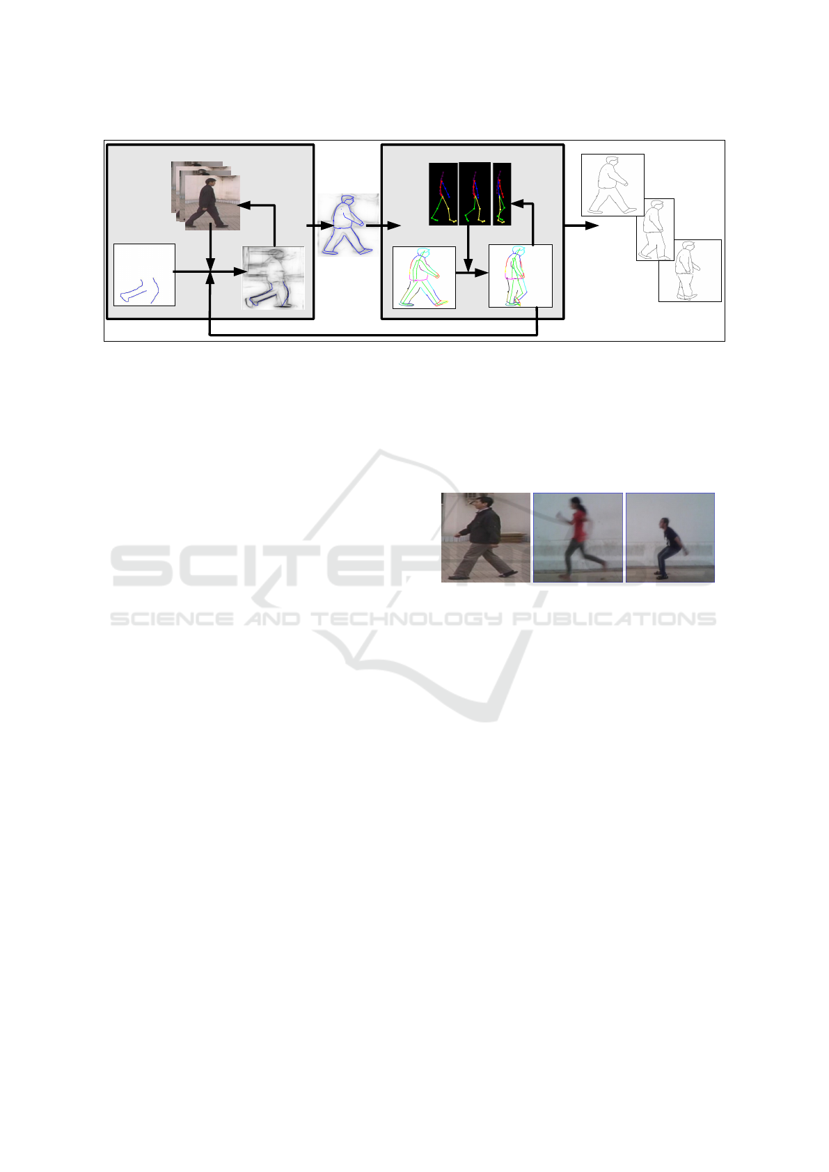
Static Pose Hint
Moving Pose Hint
Animation
(b)
(a)
(c)
(d)
(e)
(f)
(g)
(h)
Figure 2: Overview of the TraceMove System.
the sketch by clicking joint positions on the sketch
(Figure 2(f)). This has to be done only for one pose
for the entire animation. The order of clicking is
shown to the animator and automatically establishes
joint correspondences to the skeleton hierarchy used
in the motion capture. The skeleton on the sketch is
used to identify a best matching pose from the mo-
tion capture data, and the subsequent poses to the best
matching pose, are used to find corresponding sub-
sequent poses for the skeleton on the sketch, and by
consequence of the sketch itself (Figure 2(g)). At this
point, the animator can choose to manually edit the
predicted sketched pose, again with the help of the
static pose hint or without it. This process is repeated
to get sketches for all the frames of the animation.
It should be noted that the animator can choose to
ignore the static and moving pose hints completely at
any stage, or use them at any stage in the creation pro-
cess. So the system does not stifle the freedom of the
animator, but provides enough help to the novice an-
imator to be able to create convincing sketched char-
acter animations.
The static pose hint generation module of our sys-
tem is based on ShadowDraw (Lee et al., 2011). Our
static pose hint is like the shadow image generated
in that work. We have implemented our system from
scratch and have made some changes to the original
ShadowDraw idea which improve the quality of the
generated hint.
The first part of the static pose hint generation
module involves processing a database of figures of
human in various poses during a motion. For walk-
ing people, we used the CASIA Gait Database (Wang
et al., 2003). For other motions, we created our
own database by recording videos of various motions
on 6 different users. We used the frames of these
videos as figures in our database, In total the com-
bined database has 3052 frames for 6 different kinds
of motion. Example images from the database can
be seen in Figure 3. The database is processed of-
fline, in a pre-processing step to generate a database
of patch-features from the edge figures of the figures
in the original database. These descriptors are then
used to generate the static pose hint while the user
sketches.
Figure 3: Example images from the image database.
3.1 Generating the Database of
Patch-features
The original figures in the database are converted to
edge figures, post cropping and size normalization.
We use (Dollr and Zitnick, 2013) to extract long edges
from the figures. This is important because it is found
that while sketching it is natural to draw the long
edges first. So we need an algorithm that can prior-
itize long edges. ShadowDraw (Lee et al., 2011) uses
the work presented in (Bhat et al., 2010) for extract-
ing edges. Our implementation of the same gave ei-
ther faint or very thick edges, so we used the different
method mentioned above.
This is followed by dividing the edge image into
overlapping patches and computing a BICE descrip-
tor for each patch (Zitnick, 2010). We want to match
the user’s sketch to the figures in the database, in de-
scriptor space. However, computing a match directly
on the descriptor is expensive so it is converted to a
sequence of k values, each generated by applying k
different min-hash functions to the descriptor of the
patch. Each sequence of these k values is a patch-
feature. This is repeated n times, using a different
TraceMove: A Data-assisted Interface for Sketching 2D Character Animation
193

set k hash functions each time, to get n patch-features
for each patch descriptor. Therefore while match-
ing, a potential input patch has to match multiple in-
stances of the same descriptor to be considered a good
match. This reduces both false positives and false
negatives. We have used k = 3 and n = 20. We store
the patch-features with a reference to the original im-
age to which they belong, and the patch location co-
ordinates in the original image in another database.
Figure 4: First column shows the drawn sketch overlaid
on the static pose hint, second and third columns show the
static pose hint and the drawn sketch separately.
3.2 Generating the Static Pose Hint
As soon as the animator finishes sketching a stroke,
an image of the canvas is converted to patch-features
and only patches containing the strokes are matched
to the database created in the previous section. Top
10 figures from which maximum number of patch-
features match the patch-features from the input
sketch are aligned and blended. This blended im-
age is then multiplied with its own blurred version to
strengthen edges that match in position between them
and weaken others. This forms the static pose hint im-
age. It is displayed on the drawing area, underlying
the animator’s sketch, and can be updated in real-time
as the animator sketches. We have, however, found
this to be distracting during use. So we give the ani-
mator an option of updating and displaying the static
pose hint on the canvas at the push of a button, in-
stead of updating it continuously on sketching. The
last updated static pose hint is displayed on the side
in a smaller window so that the animator still has a
reference for the pose being sketched but the drawing
area is not obstructed by it. An example of the static
pose hint is shown in Figure 4
4 MOVING POSE HINT
After successfully drawing the character in a particu-
lar pose, the animator now wants to sketch the pose
in the next frame of the animation. The moving
pose hint is meant to help with this. We start with
a database of motion capture clips. This database cur-
rently has 6 different kinds of motions and a total of
625 frames. We project the 3D motion capture data
to 2D, using a camera that projects the root node of
the motion capture skeleton to the origin of the image
coordinate system. We fix other camera parameters
to give us desired projections of the motions being
processed. It should be noted that we can only gen-
erate moving pose hints if the sketch of the character
is from the a viewpoint that is close to the camera
viewpoint used to generate the 2D projections of the
motion capture data. The creation of the 2D projected
motion capture database is a pre-processing step and
has to be performed only once.
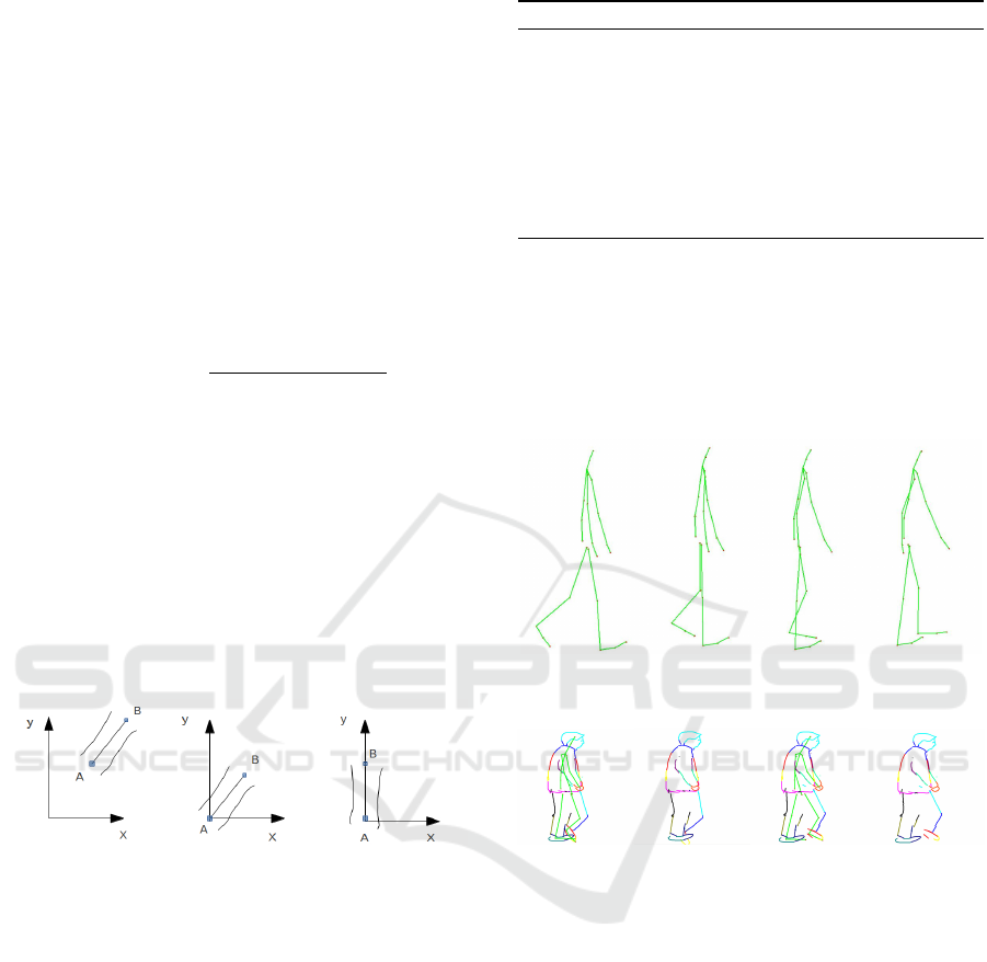
4.1 Skeleton Matching
The animator marks the skeleton on the sketch of the
current pose by clicking the joint positions on the
sketch. The joints have to be clicked in a particular
order that is shown in the interface during the click-
ing (as shown in Figure 5(a)). This has to be done
only once for a single sketched pose of the entire an-
imation and is very simple to do. The ordered click-
ing automatically sets up correspondence between the
user marked skeleton and the motion capture skeleton.
(a) (b)
Figure 5: (a) Order in which the skeleton nodes have to
marked by the user, (b) Joint nodes for left arm have to
marked even when it is occluded.
The animator has to mark the entire skeleton even
if a part of the body is occluded in the current sketch.
GRAPP 2016 - International Conference on Computer Graphics Theory and Applications
194

For example, as shown in Figure 5(b), one arm of the
character may be occluded but all the skeleton nodes
for that limb have to marked approximately.
After the skeleton is marked on the sketch, its
bones are re-scaled to match the bone length of the
skeleton in the motion capture database. This is nec-
essary because the bone lengths of the motion capture
skeleton are fixed, while bone lengths of the sketch
skeleton can vary with the sketch. Therefore, we
determine scale factors needed to scale the sketched
skeleton bones appropriately. If S
i
is the scale factor
for i
th
bone, L
sketch
i
and L
mocap
i
are bone lengths of i
th
bones of the skeleton on the sketch and in the motion
capture database, respectively.
S
i
=
L
mocap
i
L
sketch
i
(1)
This scale factor is applied to each bone of skele-
ton on the sketch. We also calculate the inverse scale
factor, IS
i
= 1/S
i
that is used later in our calculations.
After scaling the skeleton on the sketch, the sys-
tem searches for the best matching frame in the mo-
tion capture data such that the pose of the skeleton
in that frame best matches the sketched pose. This
is done by minimizing, over all frames, a distance
metric that sums the Euclidean distance between the
corresponding root-centred joint coordinates of the
sketch and motion capture skeleton joints.
D
t
= min
t
{
∑
k
dist(C
sketch
k
,C
mocap
k
,t
k
)} (2)
Here D
t
is the minimum value of distance metric,
C
sketch
k
is the coordinate of the k
th
joint of the sketched
skeleton with the root of the skeleton as the origin,
and the C
mocap
k
is the similar coordinate of the corre-
sponding joint of the skeleton in the motion capture
data and t iterates over all the frames of the database.
Now we can predict the next pose for the sketch from
the pose of the skeleton that follows the best matching
skeleton in the motion capture data. This predicted
sketch is the motion pose hint. But before we can do
that we need to be able to deform the sketched pose
using the skeleton. This requires us to rig the sketch
with the sketched skeleton.
4.2 Rigging
In order to facilitate rigging, every sketch stroke is in-
ternally converted to a B
´
ezier curve. Rigging is com-
puted automatically by the system on the basis of dis-
tance of the curve points from skeleton bones. Every
curve point is associated with at least one skeleton
bone. Curve points near a skeleton joint are associ-
ated to both bones at the joint. Weights are assigned
to the curve points by inverse weighting them by their
distance from the bone.
Due to ambiguity of 2D projection, there are cases
where automatic rigging incorrectly associates curves
with skeleton bones. This causes erroneous deforma-
tion of the sketch when the skeleton moves. In such
cases, animator can correct this simply by going to
manual rig mode and selecting the curve that need to
be re-associated and the bone with which it needs to
be associated by clicking on it. This will detach the
curve from its initial bone and re-associate it to the
new bone.
Figure 6(a) shows an incorrect automatic rigging
output. Curves associated with different skeleton
bones are of different colour. The curves of the torso
get wrongly associated to an arm and move back-
wards as the arm swings back in a subsequent frame
in Figure 6(b), as indicated by the red arrows. Fig-
ure 6(c)-6(d) shows the corrected rigging in the initial
frame and how it stays in position correctly in the gen-
erated sketch for the following frame, as indicated by
the green arrows.
(a) (b)
(c) (d)
Figure 6: (a), (b) Automatic Rigging, (c), (d) Corrected Rig-
ging.
4.3 Binding Matrix Calculation
The curves are defined in screen space and skeleton
joints are defined in their own local frame. The curve
associated with a particular bone need to be defined
in the same frame as that of the bone so that all the
transformation that are applied to joint, when applied
to curve will move the curve along with the bone. To
TraceMove: A Data-assisted Interface for Sketching 2D Character Animation
195
define the curve points in the joint space with which
they are associated we need to find the binding ma-
trix for all the skeleton joints. This binding matrix,
B when multiplied to the curve points, transfer them
to the joint local coordinate frame, with Y -axis along
the bone, X- axis perpendicular to the bone and par-
ent node as the origin. The binding matrix for the k
th
joint is calculated as
B
k
=
cosθ −sin θ 0
sinθ cosθ 0
0 0 1
1 0 −J
k
x,
0 1 −J
k
y
0 0 1
(3)
Here
L
k+1
= J
k+1
− J
k
D =
q
(L
k+1
x)
2
+ (L
k+1
y)
2
cosθ = L
k+1
y/D
sinθ = L
k+1
x/D
J
k+1
is the coordinate of k + 1
th
joint and L
k+1
is
its coordinates with respect to its parent, i.e., k
th
joint.
Now, for curve associated with k
th
joint, the binding
matrix is the product of a rotation matrix and a trans-
lation matrix. First, the translation matrix is applied
to the curve which will bring the k
th
joint to the origin
and then rotation matrix is applied to align the bone
with the Y -axis as shown in Figure 7.
Figure 7: (a) A bone and the associated curve, (b) Trans-
lated to origin (c) Rotated so that bone lies along Y -axis.
4.4 Generating the Moving Pose Hint
We have found the frame from the motion capture
database that best matches the sketched skeleton. We
also know the pose of the skeleton in the frame that
follows the best frame in the motion capture data.
The system now finds the translation difference in
coordinates for these two frames in the motion cap-
ture database and applies that difference to the current
sketched skeleton, after inverse scaling it to drawn
skeleton. This is done using Algorithm 1.
Here T
k
is the translation difference for k
th
joint.
J
t+1
k
and J
t
k
are the 2D coordinates of k
th
joint for next
frame and current frame of the motion capture skele-
ton respectively. Note that the translation difference is
calculated by taking parent joint node as origin. Sim
ilarly in the subsequent step, when applying this dif-
Algorithm 1: Generate Next Sketch Skeleton.
1: for every joint k of the motion capture skeleton in
frames t and t + 1 do
2: T
k
= (G
t+1
k+1
− G
t+1
k
) − (G
t
k+1
− G
t
k
)
3: end for
4: for every bone i of the sketched skeleton between
joints J
k+1
and J
k
do
5: J
t+1
k+1
= (J
t
k+1
− J
t
k
) + IS
i
· T
k
+ J
t+1
k
6: end for
ference to sketched skeleton joint J
k+1
, its parent joint
J
k
is shifted to origin. After applying the difference
to the (k + 1)
th
joint, the k
th
joint is shifted back to
its new position that is calculated after applying the
translation difference to it. The coordinates given by
the J
t+1
’s are the new predicted position of the joints
of the sketched skeleton in the next frame.
Figure 8: First frame is the drawn skeleton, rest of the
frames are generated using Algorithm 1.
(a) (b) (c) (d)
Figure 9: (a) Current frame with skeleton,(b) Current frame
without skeleton, (c) Next Frame with skeleton, (d) Next
Frame without skeleton.
We find the transformation matrix from the current
sketch skeleton to the next generated sketched skele-
ton for every skeleton joint. We apply this transfor-
mation matrix and the binding matrix to every curve
associated with a particular joint, to generate the mov-
ing pose hint. This is illustrated in Figure 9.
4.5 Depth Adjustment
Since a sketch is 2D, some of the curves that were
visible before may go behind the body and they will
still be visible. For correct occlusion handling, these
have to be erased via manual editing. While some new
curves that were occluded before may be visible in the
new frame. The animator will have to draw them. For
this purpose, she can take help of the static pose hint
GRAPP 2016 - International Conference on Computer Graphics Theory and Applications
196

Figure 11: Frames from walk animation.
Figure 12: Frames from another walk animation with a different character.
Figure 13: Frames from a run animation.
Figure 14: Frames from a skipping animation.
again, if required. This is shown in Figure 10. The
newly drawn curves get automatically attached to the
skeleton via automatic rigging.
(a) (b) (c)
Figure 10: (a) First frame, (b) Next frame without depth
adjustment, (c) Next frame with depth adjustment.
5 RESULTS
We present examples of seven sketched animations
generated using our TraceMove system for various
kinds of motion. These were all created by two novice
animators who had no prior experience in hand-drawn
figure animation. The actual animations can be seen
in the supplementary video submitted with this paper.
6 CONCLUSION
We have presented a system to assist novice anima-
tors in sketching 2D character animations. The sys-
tem generates a static pose hint to help in the sketch-
ing of a particular pose of a character in a frame of the
animation and also generates a moving pose hint that
helps sketch the subsequent frame of the animation,
given the current frame. Both these hints are gener-
ated with the help of pre-processed, stored databases
of images and motion capture data.
The current system has certain limitations. The
sketches for which the moving hint can be generated
must be from a viewpoint that is close to the one
used in generating the 2D projected motion capture
database. This can be overcome by automatic view-
point detection on the sketch and then using the corre-
sponding view of the 3D motion capture data at run-
time. Also, during the entire sketch animation that
can be generated by the system, the camera orienta-
tion relative to the character cannot change much. The
hint generation modules cannot work across view-
point changes. A view-dependent hint generation
method can possibly be used to alleviate this problem.
We also want to test the system with more novice
TraceMove: A Data-assisted Interface for Sketching 2D Character Animation
197
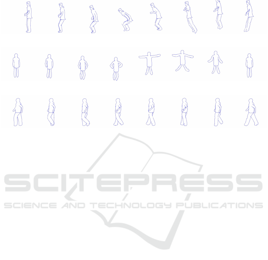
Figure 15: Frames from a jump animation.
Figure 16: Frames from a different jumping animation.
Figure 17: Frames from a backward walk animation.
animators and also, expert animators, to understand
the efficacy of our interaction paradigms. This would
require a thorough user study. We currently have no
way to measure the aesthetic quality of the generated
animation, but the novice animators who have used
our system agree that it made the task of creating the
animation easier for them and gave them a handle on a
skill that they would have otherwise struggled to mas-
ter. We want to use this positive feedback to further
improve our system and make it more intuitive and
natural to use.
REFERENCES
Bae, S., Balakrishnan, R., and Singh, K. (2009). Every-
bodylovessketch: 3d sketching for a broader audience.
In Proceedings of ACM Symposium on User Interface
Software and Technology, pages 59–68.
Bhat, P., Zitnick, C. L., Cohen, M., and Curless, B.
(2010). Gradientshop: A gradient-domain optimiza-
tion framework for image and video filtering. ACM
Transactions on Graphics, 29(2):10:1–10:14.
Chen, T., Cheng, M.-M., Tan, P., Shamir, A., and Hu, S.-M.
(2009). Sketch2photo: Internet image montage. ACM
Transactions on Graphics, 28(5):124:1–124:10.
Davis, J., Agrawala, M., Chuang, E., Popovi
´
c, Z., and
Salesin, D. (2003). A sketching interface for artic-
ulated figure animation. In Proceedings of the 2003
ACM SIGGRAPH/Eurographics Symposium on Com-
puter Animation, pages 320–328.
De Paoli, C. and Singh, K. (2015). Secondskin: Sketch-
based construction of layered 3d models. ACM Trans-
actions on Graphics, 34(4):126:1–126:10.
Dixon, D., Prasad, M., and Hammond, T. (2010). icandraw:
Using sketch recognition and corrective feedback to
assist a user in drawing human faces. In Proceedings
of the SIGCHI Conference on Human Factors in Com-
puting Systems, pages 897–906.
Dollr, P. and Zitnick, C. L. (2013). Structured forests for
fast edge detection. In Proceedings of the 2013 IEEE
International Conference on Computer Vision, ICCV
’13, pages 1841–1848. IEEE Computer Society.
Igarashi, T., Matsuoka, S., and Tanaka, H. (1999). Teddy:
A sketching interface for 3d freeform design. In Pro-
ceedings of the 26th Annual Conference on Computer
Graphics and Interactive Techniques, SIGGRAPH
’99, pages 409–416.
Jacobs, C. E., Finkelstein, A., and Salesin, D. H. (1995).
Fast multiresolution image querying. In Proceed-
ings of the 22nd Annual Conference on Computer
Graphics and Interactive Techniques, SIGGRAPH
’95, pages 277–286.
Jain, E., Sheikh, Y., and Hodgins, J. (2009). Leveraging the
talent of hand animators to create three-dimensional
animation. In Proceedings of the 2009 ACM SIG-
GRAPH/Eurographics Symposium on Computer An-
imation, pages 93–102.
Lee, Y. J., Zitnick, C. L., and Cohen, M. F. (2011). Shadow-
draw: Real-time user guidance for freehand drawing.
ACM Transactions on Graphics, 30(4):27:1–27:10.
Levi, Z. and Gotsman, C. (2013). ArtiSketch: A system
for articulated sketch modeling. Computer Graphics
Forum, 32(2):235–244.
Li, Y., Gleicher, M., Xu, Y.-Q., and Shum, H.-Y. (2003).
Stylizing motion with drawings. In Proceedings of
the 2003 ACM SIGGRAPH/Eurographics Symposium
on Computer Animation, SCA ’03, pages 309–319.
¨
Oztireli, A. C., Baran, I., Popa, T., Dalstein, B., Sumner,
R. W., and Gross, M. (2013). Differential blending
for expressive sketch-based posing. In Proceedings of
GRAPP 2016 - International Conference on Computer Graphics Theory and Applications
198

the 12th ACM SIGGRAPH/Eurographics Symposium
on Computer Animation, pages 155–164.
Pan, J. and Zhang, J. J. (2011). Transactions on edutainment
VI. chapter Sketch-based Skeleton-driven 2D Anima-
tion and Motion Capture, pages 164–181.
Thomas, F. and Johnston, O. (1995). The Illusion of Life:
Disney Animation. Hyperion.
Thorne, M., Burke, D., and van de Panne, M. (2004). Mo-
tion doodles: An interface for sketching character mo-
tion. In Proceedings of ACM SIGGRAPH 2004, pages
424–431.
Wang, L., Tan, T., Ning, H., and Hu, W. (2003). Silhoutte
analysis based gait recognition for human identifica-
tion. IEEE Transactions on Pattern Analysis and Ma-
chine Intelligence (PAMI), 25(12):1505–1518.
Williams, R. (2009). The Animator’s Survival Kit–Revised
Edition: A Manual of Methods, Principles and For-
mulas for Classical, Computer, Games, Stop Motion
and Internet Animators. Faber & Faber, Inc.
Xu, B., Chang, W., Sheffer, A., Bousseau, A., McCrae, J.,
and Singh, K. (2014). True2form: 3d curve networks
from 2d sketches via selective regularization. ACM
Transactions on Graphics, 33(4).
Yang, R. and W
¨
unsche, B. C. (2010). Life-sketch: A frame-
work for sketch-based modelling and animation of 3d
objects. In Proceedings of the Eleventh Australasian
Conference on User Interface - Volume 106, pages 61–
70.
Zitnick, C. L. (2010). Binary coherent edge descriptors.
In Proceedings of the 11th European Conference on
Computer Vision (ECCV), pages 170–182.
TraceMove: A Data-assisted Interface for Sketching 2D Character Animation
199
