
Intelligent Robotic Approach for After-stroke Hand Rehabilitation
Nirvana Popescu
1
, Decebal Popescu
1
and Mircea Ivănescu
2
1
Department of Computer Science, University Politehnica of Bucharest, Bucharest, Romania
2
Department of Mechatronics, University of Craiova, Craiova, Romania
Keywords: Post-Stoke Rehabilitation, Robotic Glove, Intelligent Control, Speech Recognition.
Abstract: This paper presents the design of an intelligent haptic robotic glove (IHRG) model for the rehabilitation of
the patients that have been diagnosed with a cerebrovascular accident (CVA). Total loss or loss of range of
motion, decreased reaction times and disordered movement organization create deficits in motor control,
which affect the patient’s independent living. The control system for a rehabilitation hand exoskeleton is
discussed. One contribution is given by using a velocity observer and a force observer for performance
evaluation. The disturbance effects are eliminated by a cascade closed loop control with velocity and force
observers. The performance of the control system is demonstrated by the simulation. The second proposed
control implementation version has a great advantage - the possibility to specify some vocal commands, which
will help the patient to make a lot of medical exercises by themselves.
1 INTRODUCTION
The scientific community has become increasingly
interested in so-called Rehabilitation Robotics, a
branch of the areas of Robotics and Mechatronics that
addresses to the study of complex robotic systems
aiming to restore the human functions for those
people who suffer major trauma as a result of strokes
and cerebrovascular accident (CVA). A CVA occurs
when a blood vessel (an artery) that supplies blood to
an area of the brain bursts or is clogged by a blood
clot. Within minutes, the nerve cells in that area are
affected and they can die in a few hours. As a result,
the part of the body that is controlled by the affected
area of the brain cannot function properly
(Grebenstein, 2010).
Total loss or loss of range of motion, decreased
reaction times and disordered movement organization
create deficits in motor control, which affect the
patient’s independent living. Recent studies have
shown that intensive and repetitive training may be
necessary to modify neural organization and recover
functional motor skills. Several researchers
(Reynaerts, 1995; Rodriguez-Cheu and Casals, 2006;
Zhao et.al., 2006; Lucas et.al. 2004) have reported
significant improvement in patients’ daily activities
due to higher training intensities, even in the CVA
chronic phase. However, there were several opinions
in the literature claiming that the repetitive training is
not very efficient (French et al., 2010) and other
papers proved that there are some reduced
improvements (Barbay et al., 2013). On the other
hand there are authors that certified the improvement
arm movement ability (Housman et al., 2009).
The current health care system provides stroke
rehabilitation in the intensive care hospital setting, in
the rehabilitation setting and in the outpatient setting.
In the last decade, the literature presented numerous
concepts and techniques that allow evaluation of the
hand physiological properties, structure,
characteristics and especially the functional anatomy.
There is a great need to develop new approaches for
rehabilitation of the upper limb after stroke. Robotic
therapy is a promising form of neurorehabilitation
that can be delivered in more intensive regimens than
conventional therapy (Kitago et al. 2015). Numerous
studies (Carrozze et.al. 2003; Birglen and Gosselin,
2003, 2004; Biagiotti et.al., 2009, Lotti and Vassura,
2005, Brokaw et.al. 2011, Jiting et.al., 2011) have
allowed the development of kinematic structures to
reproduce as much as possible the human hand
kinematics.
This paper presents the design of a low-cost
Intelligent Haptic Robot-Glove (IHRG) for the
rehabilitation of the patients that have been diagnosed
with a cerebrovascular accident (CVA). The IHRG is
an exoskeleton that supports the human hand and
hand activities by using a control architecture for
dexterous grasping and manipulation. IHRG is a
Popescu, N., Popescu, D. and Iv
ˇ
anescu, M.
Intelligent Robotic Approach for After-stroke Hand Rehabilitation.
DOI: 10.5220/0005662400490057
In Proceedings of the 9th International Joint Conference on Biomedical Engineering Systems and Technologies (BIOSTEC 2016) - Volume 5: HEALTHINF, pages 49-57
ISBN: 978-989-758-170-0
Copyright
c
2016 by SCITEPRESS – Science and Technology Publications, Lda. All rights reserved
49
medical device that acts in parallel to a hand in order
to compensate some lost function.
In order to design an exoskeleton structure and to
develop techniques that allow rehabilitation of the
main anatomical features of the hand, in the context
of extremely varied range of patients with various
problems of malfunction, the architecture presented
in this paper should cover the range of issues and
anatomical structures.
Feedback is important in rehabilitation.
Rehabilitation is most effective when users get
immersive feedback that relates to the activities they
imagine or perform. For example, if people imagine
grasping an object with their left hand, then an image
of a grasping hand can help users visualize their
activity. If a stroke patient keeps trying to imagine or
perform the same movement, while receiving
feedback that helps to guide this movement, then
users might regain the ability to grasp, or at least
recover partial grasp function. In the last few years,
totally novel and promising application for motor
imagery (MI) - based Brain-Computer Interface
(BCI) has gained attention (Irimia et al, 2012, 2014).
In the case when patients can talk and the stroke
did not affect their vocal capacity of pronouncing
words, a new design of IHRG is also presented in this
paper. The implementation is made based on some
hardware platforms. One of them is Arduino Mega
2560 which is a hardware platform that determines
the movement of some small engines that will help
the patient to open or close one or more fingers. The
second one is the Raspberry Pi hardware platform
which was used in order to make all the calculations
specific to voice recognition. Using a microphone, the
patient can send vocal commands to IHRG or can
select one predefined program which will imply some
exercises for a specific period of time.
One major contribution of this paper consists of
using observers for this type of rehabilitation system.
All the analysed papers, some of them being included
in the state of the art of this work, have used velocity
sensors for performance evaluation. Instead, we used
velocity observers and force observers for doing this.
The second contribution regards the voice recognition
based implementation that offers the facility of live
interaction between the system and the patient.
The paper is structured as follows: section II
presents the design and development of the structure
of the intelligent haptic robotic glove that includes
hand biomechanics, the exoskeleton architecture and
the control architecture; section III shows a different
control approach based on voice recognition and
details the hardware implementation in this case;
section VI is concerned with conclusions.
2 DESIGN AND DEVELOPMENT
OF IHRG STRUCTURE
For a correct analysis of hand function, a researcher
must thoroughly analyse three main components: the
upper hand and wrist, fingers (four) and thumb.
Different biomechanical movements of flexion,
extension, abduction and adduction were analysed,
considering the amplitudes, movement directions,
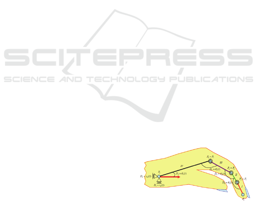
axes and planes. The model of hand articulations is
presented in Figure 1.
Carpal osteoarticular complex is so constituted as
to permit carrying out movements of flexion-
extension, abduction – adduction and circumduction.
Because these joints are plane, each of them allows
sliding movements of small amplitude. Wrist joint
movements occur simultaneously: both in radiocarpal
and mediocarpal joints. All these movements are
accomplished by sequential displacement of region
segments: the second carpal (distal) moves on the first
carpal (proximal) and then the latter slipped on the
forearm. Functional position of the hand is the active
position, ready to grab. This means that hand makes
a dorsal flexion with 20°, the fingers are slightly
flexed and the thumb is in opposition. The muscles
are slightly tensed; the extensors of the hand and the
flexors of fingers exert a dominant action on
antagonists. This is an important aspect since in the
case of stroke occurrence and central level control
interruption, this normal anatomic position is
accentuated being accompanied by spasticity.
Using haptic interface technology allows for
reaching and grasping movement executed by hand to
be assisted by a robot that direct the movement to a
specific target. Until now, the technologies developed
for this purpose have the potential to revolutionize the
way hospitals operate, reducing the recovery stroke
cost while allowing therapists and clinicians to
manage a large number of patients in the same period
of time.
Figure 1: Hand joints model.
HEALTHINF 2016 - 9th International Conference on Health Informatics
50
2.1 The Exoskeleton Architecture
One of the proposed solution is to develop a
mechanical architecture consisting of a cascade of
articulated elements, whose design to cover as much
as possible the anatomic and functional finger
phalanges, providing support for the actuation
system.
Two architectures were analysed: the 4-bar
mechanism and the tendons mechanism. In tendons
mechanism architecture, the three phalanges of the
finger are realized as a serial structure of three
rotation joints, each joint being controlled in cascade
by the previous joint through a tendon-cable that is
coupled on the pulleys system associated with each
joint. In this case, kineto-static analysis principles
were studied. Then it was considered a finger
architecture based on 4-bar mechanism where the
movement is achieved by successive deformations of
the 4-bar mechanisms associated with each phalanx
of the finger.
The proposed architecture is a control architecture
where the control is performed at the first active joint,
the other joints being passive and realizing
movements based on the associated bar system
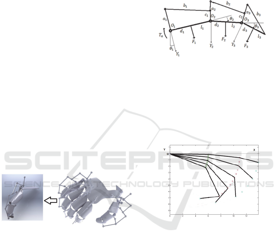
(Popescu et.al., 2013). The global architecture of one
finger exoskeleton and of the entire structure can be
seen in Figure 2.
Figure 2: The global architecture of one finger exoskeleton
and of the whole hand.
2.2 The Control Architecture
The control architecture was developed considering
that the control is performed at the first active joint,
the other joints being passive and realizing
movements based on the associated bar system. The
proposed overall structure is shown in Figure 3.
It can be observed the distribution of forces on the
phalanges. A kinetostatic analysis was performed, the
movement of three phalanges being realized planar.
A coordinate system X
i
, Y
i
, O
i
and an articulated bar
system with parameters: a
i
, b
i
, c
i
are assigned to each
phalanx of l
i
length. The finger movement is achieved
by rotating each finger phalanx withe the angles θ
1
,
θ
2
, θ
3
. The control forces on the external environment,
F
1
, F
2
, F
3
are applied in d
1
, d
2
, d
3
representing the
contact points on a human hand. It is considered the
active torque T
a
applied on the finger joint 1.
Figure 3: The 4-bar mechanism architecture of a phalanx.
Our approach also proposes a control scheme
dedicated to underactuated fingers with the intention
of maximizing the capabilities of the control using
position information. Position sensors are
implemented on the mechanical transmission system
and used to enhance the behaviour of the hand despite
its limited number of control signals. Several
positions of a finger in a rehabilitation exercise are
illustrated in Figure 4.
Figure 4: Finger motion for a rehabilitation exercise.
The control system needs self-tuning to adjust
dynamics and kinematics of the system. This self-
tuning has to compensate effects of internal and
external disturbances: model uncertainty, load,
friction and compliance with human finger. In some
research works, the force control for grasping is
obtained by using tactile feedback. The limited space
on the finger surface makes very difficult the
introduction of a sensor on that area. For this reason,
velocity and force observers are used to implement
the control technique.
The actuation system for each finger is based on
one dc motor moving a slider device which transmits
motion to the phalanges by several coupled „four-
bar” mechanisms. The dynamic model of the
Intelligent Robotic Approach for After-stroke Hand Rehabilitation
51
actuation system and load mechanism is described by
the following equations
(1)
(2)
(3)
(t)
(4)
where
,,, are the state parameters: the drive
current, mechanical angular velocity, angular
position, motor torque, respectively,
,,
represent the electrical motor parameters: armature
inductance and resistance and back EMF constant,
respectively, and
,
,
,
are mechanical
parameters: nominal inertia, damping constant,
nominal torque constant and spring constant. Also
is an equivalent disturbance torque that focuses
the effect of friction, external forces determined by
the compliance with human finger and unmodeled
dynamics in the transmission mechanism.
The design of the force observer is based on
(Lucas et.al., 2004) and estimates the force from the
dynamic model of motion, avoiding the use of the
acceleration signal, measured or construct from
velocity by differentiation. By using (2), (4) (with
0, the force observer is defined by
̂
(5)
where
̂ is the estimated force-torque and
represents the observer gain (in order to simplify
the notation, the variable
is omitted). We select the
observer gain as
L = α / J, α > 0 (6)
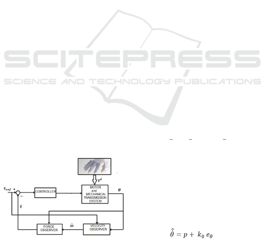
A classical cascade disturbance closed loop
control is proposed in Figure 5. The system contains
the actuation system, mechanical transmission system
and a conventional controller (for example, a PID
controller). Measuring signal is the angular position
.
Figure 5: A cascade closed loop control with observers.
A velocity observer is used to generate the estimated
value of velocity
using the reference value of the
torque, τ
ref
This signal is used in the force observer to
generate the estimated value of the torque
̂. The
forces between hand and exoskeleton act as the
disturbances
. The classical conventional tuning
rules are used for the control parameters in order to
compensate the disturbances and to ensure the motion
performances. The disturbances are determined by
the resistance increasing to passive finger extension.
Characterization of hypertonia can be difficult due to
the highly variable nature of the hyperactivity of the
finger flexors and the characteristics of each patient.
The observer error will be
= ̂
(7)
From (6) yields
(8)
We assume that the torque varies slowly relative
to the observer dynamics (Lucas et al., 2004; Chen et.
al., 2000; Xian et.al., 2004)] and it was supposed that
0
(9)
In terms of this condition, from (5), (10), the error
dynamics becomes,
/
(10)
that proves that the observer is globally
asymptotically stable. The parameter
∝ determines
the time constants for the estimation. In order to
simplify the observer construction, a function
is
defined as
̂
(11)
By using (5), (10), (11), we obtain the new
observer equation as
∝
(12)
The equation (12) allows the estimation of the
torque using the position and velocity signals,
̂
(13)
The velocity observer aims to estimate the
inaccessible velocity signal
using only the position
. For a reference torque-force τ
ref
, the motion
equation (2) becomes
(14)
and the observer model is selected as,
(15)
HEALTHINF 2016 - 9th International Conference on Health Informatics
52
(16)
where e
θ
is the position error,
(17)
is the estimated value of the angular position
and k
0
, k
1
, and k
2
are constant positive observer design
parameters.
In order to demonstrate the performance of the
control system, a numerical simulation was realized.
So, we considered the dynamic model of the actuation
system and load mechanism described by (1)-(4),
where the electrical parameters of the dc motor are:
L=0.0138 H, R= 26.44Ω, k
i
=0.1656 Nm/A, k
e
=
0.982 Vs/rad and the mechanical
parameters of the
system are: J= 0.000254 kg m
2
k
Ω
,
k
Ω
=0.002031Nms/rad, k
s
=2.45 Nm/rad. The model
dynamics (1)-(4) are simulated in MATLAB
SIMULINK. First, the force and velocity observers
(12)-(13), (15)-(16), respectively, are implemented
(Popescu et.al., 2013).
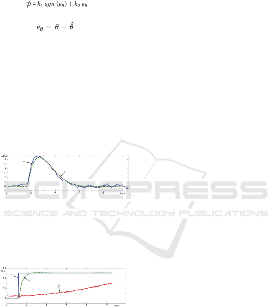
Figure 6: The estimation of velocity by observer.
The velocity signal estimated by the velocity
observer is presented in Figure 6. We remark the good
quality of estimation. This signal is used as input
variable in the force observer. A PID controller was
implemented and a cascade closed loop control
system (Figure 5) was studied. The results are
illustrated in Figure 7.
Figure 7: The force control by velocity and force observers.
3 HARDWARE
IMPLEMENTATION AND
VOICE CONTROL
In this approach, the design of IHRG is made based
on some hardware platforms. One of them is Arduino
Mega 2560 which is a hardware platform that
determines the movement of small engines that help
the patient to open or close one or more fingers. The
second one is the Raspberry Pi hardware platform
which was used in order to make all the calculations
specific to voice recognition. Based on a microphone,
the patient can send vocal commands to IHRG or can
select one predefined program which will imply some
exercises for a specific period of time (Popescu et.al.
, 2014).
The glove must be very thin in order to have a
comfortable environment for exercises. Another
aspect, which was taken into consideration, was the
fact that this type of glove is like an infrastructure
suitable for a lot of wires and sensors. The wires will
help the patient to close or open the hand, for
example, as long as the sensors will calculate real
time the resistance force generated by the patient.
All these calculations are mandatory for knowing
the action time of every engine. In fact this time
implies the force which is applied for every finger,
and this force must be correlated with the reaction
obtained from the patient in order to avoid finger
fracture. Nylon threads are used for connecting the
top fingers with the small engines. There are 5 small
engines, one for every finger and they have the major
role in implementing operations like open or close. Of
course, that these operations will be made partially –
the reaction force (the feedback) from the patient is
taken in real time and, based on these values, the
operation time for every small engine is determined.
For this purpose a bending sensor is used– one sensor
for every finger.
Another kind of sensor used in the design is the
force sensor. This sensor was added for a scenario in
which the patient will want to take some fragile
objects. These sensors are putted on the top of every
finger and will establish when the function of the
small engine will be stopped. A two-cell LiPo battery
(7.4 V) and 1000 maH battery used in design are
enough for 1 day high intensive use of the glove.
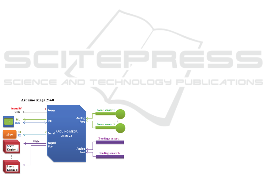
For this experiments, Arduino Mega 2560
platform was used in the implementation due to some
advantages like:
5 ports for PWM signals which are sent to the
engines,
10 analog ports which are used to read the
signals coming from the bending and force sensors,
4 serial lines – one of them is used for wireless
communication between IHRG and the speech
recognition system,
I2C busses used in order to communicate with
the LCD. On this LCD the patient can read the current
Intelligent Robotic Approach for After-stroke Hand Rehabilitation
53
program, chosen by himself, and some values for
some forces will be displayed here.
For the wireless communication (between the
intelligent glove and the control device) 2 xBee
modules were used. These modules work at 3.3V and
the Arduino board works at 5V. For this reason an
xBee adaptor must be included in the design. Another
conversion must also be realized – the battery offers
7.4V and the glove operates at 5V – using an
integrated circuit LM 7805.
The Raspberry Pi board is used to receive vocal
commands, to recognize these commands (speech
recognition) and to send these commands wireless to
the glove. The microphone and the soundboard are
connected to the Raspberry Pi board via USB port.
The whole design of the control system is shown in
Figure 8.
The software includes some libraries and open
source programs like: a voice recognition engine
(Julius HTK) which has a large words database,
Pexpect used for automatically speech recognition
and a Python module developed to control the
applications. The first step was to setup the
environment such that the Julius engine can start and
load at startup all the libraries and dependencies. In
the next step the library implementation was made.
This means to establish the vocabulary that will be
further used to control the intelligent glove. Then, the
vocabulary was translated to a phonetic form and
saved in a file with a specific extension (.voca). This
file contains every word, which will be used splitted
into the corresponding phonemes.
Figure 8: The control system of IHRG using Arduino.
These phonemes represent the sound unit of word.
The chosen language was English due to the fact that
the recognition level is very high. The English
language has usually 44 phonemes, and the
determination of them was made verifying 2 sources:
the lexicon file, which is available in Julius and the
CMU dictionary, which contains phonemes. The next
step involves rules definitions for the grammar, rules
that must be respected. After this step the result is a
file with .grammar extension in which is defined the
whole subset of possible sentences. The grammars are
described using Backus-Naur form and they will be
applied for getting the exact description of the
required language. After that, the mkdfa.pl script is
used to convert the results from the previous steps in
a Julian / Julius format. Julian is a special version of
Julius doing speech recognition based on acoustic
models.
The next step supposes as input the acoustic
models correlated with Julius HTK. In this case it is
necessary to define the configuration file used by
Julius. This is a very important step because in this
manner it is possible to define the properties for
samples creation. These samples will be processed by
HTK. When the Julius application will be started, the
patient can also start to use the vocabulary defined in
the previous steps. In the identification process, for
each word or sentence a score will be obtained. This
score will reflect the recognition accuracy level. Also,
a Viterbi score is obtained. This Viterbi score is got
via identification Viterbi algorithm for the same
sequence of hidden state.
HTK interaction involves some steps like the
following ones:
Step 1 – install the application and setup the
environment in order to have all the dependencies
available and also the libraries.
Step 2 – The acoustic models and the training
phase are done by the patient. Initially, a number of
samples and their exact form will be defined in a file.
After that the patient will register his voice using the
audacity samples defined in the file.
Step 3 – After all the samples were recorded, it is
necessary to define a configuration file that converts
the file with .wav extension to a file with .mfc
extension because only this extension is recognized
by HTK. This configuration file will be parsed by a
script, designed for the corresponding conversion.
For software configuration, in order to obtain
acoustic models in audacity, the following settings
were made: sample rate of 48Khz, 16 bits per sample,
mono channel and the resulting wave file was
converted to Microsoft 16-bit PCM format.
The software uses a Python module called
Pexpect in order to create a pseudo terminal, which is
used to connect to Julius engine. The reason is to
obtain the generated output. After that, this output is
processed using a filter for initial lines in which a
sequence is identified and a score is obtained for it.
Then, another filter is applied based on scores and
some threshold values. Finally, the value, which
HEALTHINF 2016 - 9th International Conference on Health Informatics
54
satisfies all the criteria will be recorded and translated
to a specific format which, will be further processed
by IHRG.
The communication between Raspberry Pi and
IHRG is made wireless and uses a protocol. When a
command is identified from the patient, a translation
code command is generated in order to activate the
sensors of IHRG. The codification is:
- for every bending sensor a value between 0
and 9 will be transmitted, where 0 means standby and
9 represents the maximum bending.
- for the force sensor a value between 0 and 4
will be generated, where 0 means a contact and 4
means maximum fundraising amount.
This codification is sent like a string of 6 values.
The most significant value is # and the least
significant value is ~. For example, the code #55552~
represents the command GRAB.
Table 1: Implemented commands and their codes.
wave
444440
grab
555552
soft grab
333331
strong grab
999994
point 909990
open 000000
close 777770
There are a number of 7 commands implemented
and learnt by Julius as it can be seen in Table 1, along
with their codes.
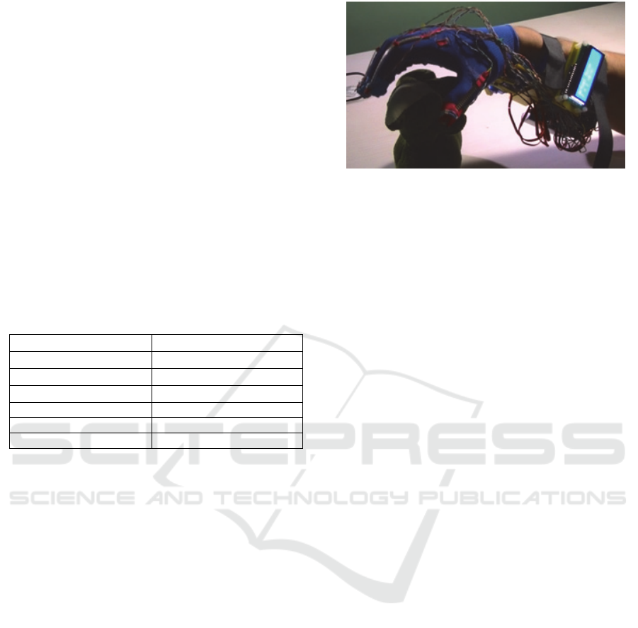
The tests that have been done have proved a very
good detection for simple commands like: open,
close, grab, point or wave. Figure 9 shows the
implemented model.
The noise is a factor which can influence the
recognition process. If the noise is almost zero, the
results of speech recognition are very good; when the
level of noise is increasing, the accuracy of speech
recognition decreases a lot. Also, in case of Raspberry
Pi the tests show that the detections of commands are
not so good like in the case in which a personal
computer is used.
The precision of results can be improved by
modifying the recorded values or changing the
Viterbi score. The training phase for the acoustic
model is also another way to improve the accuracy.
In time, the data grow up and it will be reached a point
in which the accuracy remains the same. This point is
the maximum point. In order to create an acoustic
model used by more patients, it will be mandatory as
each patient to contribute with his own audio input in
the system.
Figure 9: IHRG implementation for the voice recognition
control approach.
4 CONCLUSIONS
This paper presented the design of an intelligent
haptic robotic glove (IHRG) model for the
rehabilitation of the patients that have been diagnosed
with a cerebrovascular accident (CVA). Total loss or
loss of range of motion, decreased reaction times and
disordered movement organization create deficits in
motor control, which affect the patient’s independent
living. Some studies have shown that intensive and
repetitive training may be necessary to modify neural
organization and recover functional motor skills.
The IHRG is an exoskeleton that supports the
human hand and hand activities by using a control
architecture for dexterous grasping and manipulation.
The five-fingered assistive robotic glove was
designed with mechanical compliance of human
finger. The biomechanical elements of the
exoskeleton assistive hand were designed
considering: motion in different planes, adapted to
patient’s hand, possible to train pinch and grasp,
opening/closing game. A global architecture for the
hand exoskeleton was presented. The actuation
system was also studied and designed. The velocity
and force observers are used to implement the control
technique.
The post stroke rehabilitation robotic glove was
also designed and implemented in our laboratory
considering the fact that for any patient it will be more
comfortable to make medical exercises in his own
home. The second proposed control implementation
version has a great advantage - the possibility to
specify some vocal commands, which will help the
patient to make a lot of medical exercises by
themselves. To prove the robustness of this approach,
a lot of tests have been done and a very good detection
was obtained for simple commands like: open, close,
grab, point or wave and also for complex commands
like: soft grab or strong grab. Different factors which
Intelligent Robotic Approach for After-stroke Hand Rehabilitation
55

can influence the recognition process were also
analysed.
One major contribution of this paper consists of
using observers for this type of rehabilitation system.
All the analysed papers, some of them being included
in the state of the art of this work, have used velocity
sensors for performance evaluation. Instead, we used
velocity observers and force observers for doing this.
The second contribution regards the voice recognition
based implementation that offers the facility of live
interaction between the system and the patient. It is
also important to mention the reduced cost of the
proposed solution.
The presented approaches represent a part of a
work in progress project. We are currently involved
in testing the systems to obtain the complete results
after working with patients. This represents the
subject of a next paper.
Regarding future work, we also analyse the
possibility to implement an EEG-based brain-
computer interface that can be used to command a
semi-autonomous robotic glove by means of motor
imagery (MI). The BCI detects the intention to move
and provides online feedback to the user. At the same
time, the feedback can be used as trigger for different
pre-programmed robotic motion tasks.
ACKNOWLEDGEMENTS
This work is supported by PCCA 150/2012 grant of
the Executive Agency for Higher Education,
Research, Development and Innovation Funding
(UEFISCDI).
REFERENCES
Barbay, S., Guggenmos, D. J., Nishibe, M., Nudo, R. J.,
2013. Motor representations in the intact hemisphere of
the rat are reduced after repetitive training of the
impaired forelimb. Neurorehabilitation and neural
repair, 27: 381-384.
Biagiotti, L., Lotti, F., Melchiorri, C., Vassura, G., 2009.
How Far Is the Human Hand? A Review on
Anthropomorphic Robotic End-effectors, DEIS -
DIEM, University of Bologna.
Birglen, L., Gosselin, C., 2003. On the Force Capabilities
of Underactuated Fingers, Proc. IEEE Intl. Conf. Rob.
Aut., Taipei, Taiwan, pp. 1139-1145.
Birglen, L., Gosselin, C., 2004. Kinetostatic Analysis of
Underactuated Fingers, IEEE Trans. Rob. Aut., 20(2),
pp. 211-221.
Birglen L., Gosselin, C., 2004. Optimal Design of 2-
Phalanx Underactuated Fingers, Proc. Intl. Conf.
Intel.Manip. Grasp., Genova, Italy, pp. 110-116.
Brokaw, E.B., Black, I., Holley, R., Lum, P., 2011. Hand
Spring Operated Movement Enhancer (HandSome): A
Portable Passive Hand Exoskeleton for Stroke
Rehabilitation, IEEE Trans on Neural Systems and
Rehabilitation Eng vol 19, No4 ,August, pp391-398.
Carrozze, M.C., Vecchi, F., Sebastiani, F., Cappiello, G.,
Roccella, S., Zecca, M., Lazzarini, R., Dario, P., 2003.
Experimental Analysis of an Innovative Prosthetic
Hand with Proprioceptive Sensors, Proc. IEEEIntl.
Conf. Rob. Aut., Taipei, Taiwan, pp. 2230-2235.
Chen, W.H., Ballance, D.J., Gawthrop, P.J., O’Reilly, J.,
2000. A Nonlinear Disturbance Observer for Robotic
Manipulators, IEEE Trans on Industrial Electronics,
vol 47, No 4, August, pp 932-938.
French, B., Thomas, L., Leathley, M., Sutton, C., McAdam,
J., Forster, A., Langhorne, P., Price, C., Walker, A.,
Watkins, C., 2010. Does repetitive task training
improve functional activity after stroke? A Cochrane
systematic review and meta-analysis. Journal of
rehabilitation medicine 42: 9-14.
Grebenstein, G., 2010. A Method for Hand Kinematic
Designers, ICABB, Venice, Italy.
Housman, S.J., Scott, K.M., Reinkensmeyer, D.J., 2009. A
randomized controlled trial of gravity-supported,
computer-enhanced arm exercise for individuals with
severe hemiparesis. Neurorehabil Neural Repair 23:
505-514, 2009.
Irimia, D.C., Popescu, C.D., Poboroniuc, M.S., Ignat, B.E.,
Bolbocean, O., 2014. Using a Motor Imagery based-
BCI system for neuroprosthesis control, The 12th
Congress of the Romanian Society of Neurology,
Bucharest, Romania, Romanian Journal of Neurology
(8), ISSN online: 2069-6094, ISSN-L 1843-8148.
Irimia, D.C., Ortner, R., Krausz, G., Guger, C., Poboroniuc,
M., 2012. BCI Application in Robotics Control, 14th
IFAC Symposium on Information Control Problems in
Manufacturing, Bucharest, Romania, 14 (1): 1-6, ISSN:
1474-6670; ISBN: 978-3-902661-98-2, DOI:
10.3182/20120523-3-RO-2023.00432.
Kitago, T., Goldsmith, J., Harran, M., Kane, L., Berard, J.,
Huang, S., Ryan, S.L., Mazzoni, P., Krakauer, J.W.,
Huang, V.S., 2015. Robotic therapy for chronic stroke:
general recovery of impairment 5 or improved task-
specific skill?, Jurnal of Neurophisyhology,
114(3):1885-94. doi: 10.1152/jn.00336.2015.
Li, J., Wang, S., Wang, J., Zheng, R., Zhang, Y., Chen, Z.,
2011. Development of a Hand Exoskeleton System for
Index Finger Rehabilitation, Chinese Journal of
Mechanical Engineering Vol. 24,aNo. 5.
Lotti, F., Vassura, G., 2005. A Novel Approach to
Mechanical Design of Articulated Fingers for Robotic
Hands. DIEM, Mech.Eng. Dept, University of Bologna.
Lucas, L., DiCicco, M., Matsuoka, Y., 2004. An EMG-
Controlled Hand Exoskeleton for Natural, Journal of
Robotics and Mechatronics, Vol.16 No.5, pp 1-9.
Popescu, N., Popescu, D., Cozma, A., Vaduva, A.J., 2014.
Hardware Design and Implementation of an Intelligent
HEALTHINF 2016 - 9th International Conference on Health Informatics
56

Haptic Robotic Glove, Proc. of the the 8th
International Conference and Exposition on Electrical
and Power Engineering, EPE2014, IASI Romania,
ISSN: 978-1-4799-5848-1, 2014.
Popescu, N., Popescu, D., Ivanescu, M., Popescu, D.,
Vladu, C., Vladu, I., 2013. Force Observer-Based
Control for a Rehabilitation Hand Exoskeleton System,
Asian Control Conference (ASCC2013), pp. 1-6,
Istanbul, Turkey.
Popescu, N., Popescu, D., Poboroniuc, M., Popescu, C.D.,
2013. Intelligent Haptic Robotic Glove for Patients
Diagnosed with Cerebrovascular Accidents, 19th
International Conference on Control Systems and
Computer Science, Workshop on Medical and
Rehabilitation Engineering Applications, pp 717-721,
October, Sinaia.
Popescu, N., Popescu, D., Ivanescu, M., Popescu, D.,
Vladu, C., Berceanu, C., Poboroniuc, M., 2013.
Exoskeleton Design of an Intelligent Haptic Robotic
Glove, 19th International Conference on Control
Systems and Computer Science, vol. 1, pp. 196-201,
Bucharest.
Reynaerts, D., 1995. Control methods and actuation
technology for whole-hand dexterous manipulation, .D.
dissertation, Prod. Eng. Mach. Design Autom., Catholic
Univ. Leuven, Leuven, Belgium.
Rodriguez-Cheu L.E., Casals, A., 2006. Sensing and
control of a prosthetic hand with myoelectric feedback,
the 1st IEEE/RAS-EMBS Int. Conf. Biomed. Robot.
Biomechatron., Pisa, Italy.
Xian, C., de Queiroz, M. S., Dawson, D. M., McIntyre, M.
L., 2004. A Discontinuous Output Controller and
Velocity Observer for Nonlinear Mechanical Systems,
Automatica, 40, 4, April, pp. 695–700.
Zhao, J., Xie, Z., Jiang, L., Cai, H., Liu, H., Hirzinger, G.,
2006. A fivefingered underactuated prosthetic hand
control scheme, 1st IEEE/RAS-EMBS Int. Conf.
Biomed. Robot. Biomechatron., Pisa, Italy.
Intelligent Robotic Approach for After-stroke Hand Rehabilitation
57
