
Deriving Software Design Models from a Set of Business Processes
Estrela F. Cruz
1,2
, Ricardo J. Machado
2
and Maribel Y. Santos
2
1
Instituto Polit
´
ecnico de Viana do Castelo, Viana do Castelo, Portugal
2
Centro ALGORITMI, Escola de Engenharia,
Universidade do Minho, Guimar
˜
aes, Portugal
Keywords:
Business Process Modeling, BPMN, Use Case Model, Data Model, UML.
Abstract:
Requirements elicitation is a crucial activity and one of the first steps in software development process. A
popular way to capture and describe requirements is through UML use case models. Transforming require-
ment specifications into software design models is a complex and error prone software development activity.
Software design usually involves several models, each one representing a different perspective. One of those
perspectives is the data perspective which can be modeled using a data model. Although of the importance of
this model, few works has been done to derive a data model from use case model. The 4SRS (4-Step Rule Set)
method generates a logical architecture of a software-based system, based on a use case model. This paper
proposes an approach to adapt and extend the 4SRS method in order to generate a data model supporting the
generated logical architecture and the elicited requirements based in a set of business process models.
1 INTRODUCTION
In the software development process, one of the first
activities is the identification of the system scope and
the understanding of what the system is supposed to
do. Some software development teams base the entire
software development process on the list of require-
ments, identified in the first stage of the development
process and modeled using use case models. Another
key point in software development is the transforma-
tion of the requirements specification, modeled as use
cases, into software design models. This is mainly
because, at this stage, the problem specification starts
to be transformed into a software product solution
(Braganc¸a and Machado, 2006). That is, in fact, the
main goal of the 4SRS (4 Step Rule Set) method. The
4SRS method produces a logical architecture from the
user requirements, represented as use cases (Santos
and Machado, 2010; Machado et al., 2006). It em-
ploys successive transformations of the software ar-
chitecture in order to satisfy the elicited requirements.
This method is especially useful to make the transi-
tion from requirements modeled as use cases, to the
architecture of large and complex software systems
(Ferreira et al., 2012), because in these cases the pos-
sibility to lose or forget some detail is high and it is
very complex to manage the use cases. The 4SRS
method enables us to prevent these problems, but to
do so it requires a use case model with a high detail
level. For this, the decomposition triangle approach,
presented in (Cruz et al., 2014c), may be used help-
ing in decomposing and refining use cases to achieve
a high detail level.
In software development, different models are
usually used to represent different perspectives. The
data model is one of the most important design mod-
els for building software applications, representing
and organizing data, how it is stored and accessed,
and the relationships among different entities.
The business process management is being in-
creasingly used by organizations as a means to im-
prove their products quality and to improve their pro-
ductivity. With the aim of assuring the alignment be-
tween business processes and software requirements,
the approaches presented in (Cruz et al., 2014b; Cruz
et al., 2015) generate a use case model including use
case descriptions based on the information available
in a set of interrelated business process models. In
the approach being presented here, we intend to use
this generated use case model as input to the 4SRS
generating the logical architecture and corresponding
data model, thus supporting the set of business pro-
cess models. The approach presented in this paper
adapts and extends the 4SRS in order to generate the
data model. This way it will be possible to generate
the software system logical architecture and their sup-
porting data model.
The remainder of this paper is structured as fol-
Cruz, E., Machado, R. and Santos, M.
Deriving Software Design Models from a Set of Business Processes.
DOI: 10.5220/0005657204890496
In Proceedings of the 4th International Conference on Model-Driven Engineering and Software Development (MODELSWARD 2016), pages 489-496
ISBN: 978-989-758-168-7
Copyright
c
2016 by SCITEPRESS – Science and Technology Publications, Lda. All rights reserved
489
lows. Next section summarizes the 4SRS method and
briefly presents the language used to specify use case
descriptions. Section 3 presents the Nobel Prize ex-
ample which is used as a demonstration case. Sec-
tion 4 describes the proposed approach for data model
identification. In section 5 some related work is pre-
sented. Finally, conclusions and some remarks to fu-
ture work are presented in section 6.
2 BACKGROUND
A software logical architecture represents the soft-
ware system main components and the relation be-
tween them, allowing to understand the organization
of the system. The 4SRS method ensures the tran-
sition from user requirements specified as use case
models into software logical architectures, objects
and class models. A complete description of the 4SRS
method can be found in (Machado et al., 2006).
Nowadays, use case models are one of the most
common models used in requirements modeling and
elicitation. A use case diagram is composed by ac-
tors and use cases. Each use case shall have an asso-
ciated description. There are some alternatives that
can be used to describe a use case, such as infor-
mal text, numbered steps or pseudo-code (Cockburn,
2001). The approach presented in (Cruz et al., 2014b)
proposes a template simplifying the Cockburn’s tem-
plate, for use cases description. To fill out the use
case description template, a set of structured sen-
tences is created in Natural Language (NL). The tem-
plate and the set of sentences were originally designed
to support the automatic generation of the use case
model and corresponding descriptions based on the
existing information in a BPMN model (Cruz et al.,
2014b), or a set of BPMN models as described in
(Cruz et al., 2015). The set of sentences covers all
possible actions, flows and graphical elements present
in a BPMN model. Files (or documents) produced or
received by an activity (“transported” by a data asso-
ciation or a message flow) are attached to the corre-
sponding use case descriptions.
Sentences involving data and that, for that reason,
are relevant for deriving a data model, are listed next:
• Writes information on <data store name>.
• Reads information from <data store name>.
• Sends/Receives <document name>.
• Receives <message name> from <actor name>.
• Sends <message name> to <actor name>.
The complete set of sentences that can be used can
be found in (Cruz et al., 2014b). In this context, a
use case represents a business process activity (Cruz
et al., 2014b). Pre-conditions are used to constrain
the use cases execution order.
In this paper, the 4SRS method is adapted to deal
with use case models using a structured and con-
trolled language in use case descriptions and is ex-
tended to generate the data model (section 4).
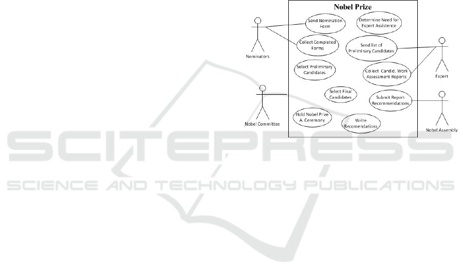
3 NOBEL PRIZE EXAMPLE
In this section we present, as a demonstration case, a
well-known and small example of the Nobel Prize.
Figure 1: Nobel Prize use case diagram.
The use case diagram generated from the original
business process model, as described in (Cruz et al.,
2014c), is shown in Figure 1. The corresponding use
case descriptions are presented in Table 1. Due to lack
of space only the descriptions of use cases considered
most important are presented. All identified use cases
are numbered using the tag=value UML mechanism.
The next section describes the approach proposed
in this paper to obtain a data model by adapting and
extending the 4SRS method. This Nobel Prize exam-
ple is used throughout the next section as a running
example.
4 DERIVING A LOGICAL
ARCHITECTURE AND THE
SUPPORTING DATA MODEL
In the approach presented herein we intend to gener-
ate the data model based on the information available
in a use case model, where each use case description
is created using a set of structured NL sentences pre-
viously defined (Cruz et al., 2014b).
The original 4SRS method is organized in 4 steps
transforming use-case models into architectural ele-
MODELSWARD 2016 - 4th International Conference on Model-Driven Engineering and Software Development
490
Table 1: The descriptions of the use cases using the defined
template.
Use case
Name
Use case Description
{U1} Send
Nomination
Form
Actors: Nobel Committee, Nominator
Trigger: The time-date September is reached.
Scenario: Read information from
<Nominator>. Around 3000 invitations
confidential nomination forms are sent to
selected Nominators. Sends the Nomination
Invitation to <Nominator>.
{U2}
Collect
Completed
forms
Actors: Nobel Committee, Nominator
Pre-condition: Send Nomination Form has
been completed.
Scenario: Receives nomination Form from
<Nominator>. Write information on
<Nominator>.
{U3} Select
Preliminary
Candidates
Actors: Nobel Committee
Pre-condition: Collect Completed forms have
been completed.
Scenario: Read information from
<Nominator>. Write information on
<Candidates>.
{U5}Send
List of
Preliminary
Candidates
Actors: Nobel Committee, Expert
Pre-condition: The Expert Assistance Re-
quired? is Yes.
Scenario: Read information from
<[Preliminary] Candidates>. Sends the
List of Candidates to be Assessed to
<Expert>.
{U6}Collect
assessment
Report
Actors: Nobel Committee, Expert
Pre-condition: Send List of Preliminary
Candidates has been completed.
Scenario: Receives assessments from
<Expert>. Write information on
<Assessment>.
{U7}Select
Final Can-
didates
Actors: Nobel Committee
Pre-condition: Collect assessment Report has
been completed.
Scenario: Read information from
<Assessment>.
{U8}Write
Recommen-
dations
Actors: Nobel Committee
Pre-condition: The Expert Assistance Re-
quired? is No OR Select Final Candidates
has been completed.
Scenario: Write information on
<Recommendations>.
{U9}Submit
Report Rec-
ommenda-
tions
Actors: Nobel Committee, Nobel Assembly
Pre-condition: Write Recommendations has
been completed.
Scenario: Read information from
<Recommendations>. Sends Recom-
mendations to <Nobel Assembly>.
ments (Machado et al., 2006). The 4SRS method ex-
ecutes a series of validations and adjustments to the
original use case model. In order to deal with struc-
tured sentences and allowing the generation of a data
model, the original 4SRS steps are slightly modified
as presented next:
• Step 1 - Architectural element creation: in this
step, the original 4SRS method proposes the cre-
ation of three types of objects for each use case:
one interface, one data and one control. However,
we are able to distinguish between persistent from
non-persistent data, as it happens in the BPMN
language (OMG, 2011). Following this idea, the
4SRS will be adapted to also distinguish persistent
data from non-persistent data, by creating two dif-
ferent types of elements involving data: persistent
data and volatile data. Each element is labeled
with the name of the use case followed by the ap-
propriate type: i (interface), c (control), dp (data
persistent) and dv (data volatile). This step can be
automated since it does not involve decisions.
• Step 2 - Architectural element elimination: based
on the textual description of each use case, it is
necessary to decide which of the four elements,
created in step 1, must be maintained. This step
allows detecting and eliminating redundancy in
requirements. This step is divided into seven
micro-steps:
– Step 2i - Use cases classification: In this micro
step each use case is classified as interface, data
persistent, data volatile, control, or any combi-
nation of these. This classification aims to facil-
itate the transformation of each use case in ar-
chitectural elements as it provides clues about
which categories of elements to use and how
they are related. Since we are dealing with a set
of structured sentences in use case descriptions,
it is possible to classify the use case following
the suggestions:
∗ When a use case exchanges information with
something or someone (usually an actor), the
i-interface type must be selected. One use
case represents the interaction with an exter-
nal participant (represented as an actor) us-
ing sentences like Receives <message name>
from <actor name> or Sends <message
name> to <actor name>.
∗ When information is stored or retrieved then
the type dp-data persistent must be selected.
Information is stored or retrieved when sen-
tences like Writes information on <data store
name> or Reads information from <data
store name> are part of the use case descrip-
Deriving Software Design Models from a Set of Business Processes
491

tion.
∗ When in a use case description we have sen-
tences like Receives <document name> or
Sends <document name>, this means that we
are dealing with non-persistent data, thus the
type dv-data volatile must be selected. It is
natural to find non-persistent data transformed
in persistent data because in a business pro-
cess, most of the times, data received from a
participant is then stored in a data store.
∗ When a use case description has a trigger,
a pre-condition or a post-condition, then the
type c-control must be selected.
Taking as example the {U6}- Collect assess-
ment Report use case (from Table 1) we may
see that the use case is receiving non-persistent
data (assessments) from expert (Receives as-
sessments from Expert), meaning that it is in-
teracting with someone, so this is classified as
i-interface and as dv-data volatile. Reading the
use case descriptions we may also see that we
are dealing with persistent data because the use
case Writes information on <Assessment>, so
the use case is also classified as dp-data persis-
tent. The use case has also controlling activities
if Send List of Preliminary Candidates has been
completed. So, the use case is also classified as
c-control. Summarizing, this use case will be
classified as c, i, dv and dp.
– Step 2ii: Local elimination - the purpose of this
micro step is to check if each architectural el-
ement created in step 1 makes sense for the
problem domain. Those that do not make sense
should be eliminated.
– Step 2iii: Architectural element naming - Each
architectural element created, should receive a
name fitting its original use case as well as the
role that it has in the system.
Taking as example the {06-dp}- Collect assess-
ment Report element created in {U6}- Collect
assessment Report use case, we may rename it
to {06-dp} - Write Assessment to better fit the
element purpose.
– Step 2iv: Architectural element description -
Each architectural element that received a name
in previous micro-step should be described ac-
cording to the corresponding system require-
ments, in order to be included in the logic
model (depicted by objects diagram).
Taking as example the {06-dp} - Write Assess-
ment element created in {U6}- Collect assess-
ment Report use case, the corresponding de-
scription may be the sentence belonging to the
original description which leads to the element
classification as dp-persistent data. The sen-
tence is Writes information on Assessment. The
other sentences will lead to the other types of
elements. This is a manual step, so the software
architect may complement the description with
other information every time it is necessary. At
this software development stage, the stakehold-
ers are still involved in the process so they can
provide useful information to complement the
information generated based on business pro-
cess models.
– Step 2v: Architectural element representation
- This micro-step, through an analysis of each
element, ensures the semantic consistency of
the logic model, detects and eliminates redun-
dancy, and enables the discovery of anomalies
in use case models, namely missing require-
ments.
Taking as example the {U1}-Send Nomination
Form and the {U3}- Select Preliminary Can-
didates use cases, we may see that both have
the same dp element (dp-Read Nominator) be-
cause both are reading information from <
Nominator>. As such, both elements can be
represented by the same dp architectural ele-
ment.
– Step 2vi: Global elimination - In this step
all micro architectural elements that are repre-
sented by other architectural elements are elim-
inated, since the requirements that correspond
to these architectural elements no longer belong
to them.
Continuing the example presented in previous
micro-step where we conclude that the {01.dp}
Read Nominator can be represented by {03.dp}
Read Nominator architectural elements or vice-
versa, one of them must be eliminated.
– Step 2vii: Architectural elements renaming -
This micro step aims to rename all the remain-
ing architectural elements.
Sometimes, when we have one architectural el-
ement, representing several architectural ele-
ments (micro-step 2v), the name of this element
may be renamed to better fit its purpose.
• Step 3: Architectural elements aggregation and
packaging - the architectural elements that remain
after the elimination, and those in which it is pos-
sible and exist advantages in their unification, are
aggregated; At this step, architectural elements
that have similar characteristics and can be treated
in an unified way are aggregated in the same pack-
age.
For example, architectural elements representing
persistent data manipulation can be package in
MODELSWARD 2016 - 4th International Conference on Model-Driven Engineering and Software Development
492

P3 - Database Control. Architectural elements
representing controlling actions are packaged in
P2 - Business rules and elements representing
user interface are packaged in P1 - User Inter-
face. The P1 - User Interface package may be di-
vided in several sub-packages representing inter-
actions with specific actors. As such, architectural
elements representing interactions with Nomina-
tor actor are packaged in P1.1 - UI Nominator.
Architectural elements representing interactions
with Expert actor are packaged in P1.1 - UI Ex-
pert and architectural elements representing inter-
actions with Nobel Assembly are packaged in P1.1
- UI Nobel Assembly (see Figure 2).
• Step 4: Architectural elements association - asso-
ciations must link the elements resulting from the
aggregation based on use cases textual descrip-
tions.
The logical architecture resulting from the appli-
cation of the 4SRS to the Nobel Prize example, is rep-
resented in Figure 2.
To define a persistent data model one needs to
identify the domain entities, their attributes, and the
relationships ((1 : n), (m : n) or (1 : 1)) between enti-
ties (Weske, 2012). Therefore, the 4SRS will be ex-
tended with three additional steps, which are:
• Step 5: Entities creation - in this step, the entities
involved in each use case are identified.
• Step 6: Relationships identification - in this step,
the relationship between the entities identified in
step 5 are identified.
• Step 7: Entity attributes identification - in this
step, the attributes belonging to each entity are
identified.
Each one of the newly added steps is explained
next.
Step 5 - Entities Creation
An entity is something identifiable, or a concept in the
real world that is important to the modeling purpose
(Weske, 2012). To identify the entities, this step is
divided into two micro-steps, explained next:
• Micro-step 5i: Entities identification - Focusing
on the {-dp} - persistent data architectural ele-
ments remaining in the generated logical architec-
ture, each read, written or updated element gives
origin to an entity in the resulting data model.
Looking at the generated logical architecture from
the Nobel Prize example, represented in Figure 2,
we may see that we are reading and writing in-
formation in Nominator, Candidates, Assessment
and Recommendations thus, each one of these
gives origin to an entity in the data model.
• Micro-step 5ii: Entities representation - This step
produces the final list of entities, by detecting and
removing the repeated entities. It is usual to find
use cases reading information that is written (or
updated) by other use cases, especially when we
are working with a large number of use cases. As
such, it is very common to identify (in the pre-
vious micro-step) the same entity several times.
These duplicated entities are eliminated.
Backing to the Nobel Prize example and looking
to the generated logical architecture (represented
in Figure 2), in {O2.dp} - Write Nominator archi-
tectural element, the entity Nominator is identi-
fied. The same entity is also identified in {O1.dp}
and {O3.dp} - Read Nominator architectural ele-
ment.
The Candidates entity may be identified in
{O3.dp} - Write Candidates and in {O5.dp} -
Read Candidates architecture elements. Both en-
tities are represented by the Candidates entity.
Similar reasoning may be used in Assessment and
Recommendations entities.
Step 6 - Relationships Identification
A relationship between two entities is represented
through an association between those entities (Chen,
1976). The role of an entity in a relationship is the
function that it executes in that relationship. A rela-
tionship between two entities can be classified accord-
ing to two aspects, Cardinality and Optionality. Both
terms are used to denote the number of attributes in
a relation. Cardinality represents the maximum num-
ber of instances (one or many) of an entity in relation
to another entity. Relationship optionality represents
the minimum number of elements that exist on that
side of the relationship. It may be 1 (the relation is
mandatory) or 0 (the relation is not mandatory).
Focusing on the elements, remaining in the re-
sulting logical architecture, that store information (el-
ements with name starting by write or update), we
must verify in which conditions the information is
stored. When an {-dp} - persistent data element is re-
lated with a {-c} - control element that verifies the in-
formation about another entity, we may conclude that
the information stored is related with the information
checked. Usually, this verification is done by read-
ing information already stored. As a consequence,
the entity that represents the written information is re-
lated with the entity that represents the checked (and
read) information. The relationship is (1:n) from the
entity that represents the information checked (previ-
Deriving Software Design Models from a Set of Business Processes
493
Figure 2: The Nobel Prize resulting logical architecture.
ously written information) to the entity that represents
the written information because the same information
can be read several times and associated to different
written information items. On the other hand the in-
formation is stored only once.
By default the relationship is mandatory on the
side of the information checked (the information must
be verified) and is not mandatory on the side of the
written entity because the information may be writ-
ten, or not, depending on the verification result.
Looking to the {06.dp} - Write Assessments ele-
ment we may see that it is related with {06.c} - Check
Candidates, so we may conclude the Assessments en-
tity is related with the Candidates entity. The same
happens between Candidates and Nominator and be-
tween Recommendations and Assessments. The rela-
tionship is (1:n) from the read to the written entity and
not mandatory from the side of the written entity.
Step 7 - Entity Attributes Identification
The information, or the properties, about an entity
are expressed through a set of attributes (Weske,
2012). Since we are dealing with use cases which
descriptions are generated from business process
models, in some cases to prevent model complexity
the properties are not identified. Nevertheless, in
some cases, especially when information is stored
or retrieved, the use case description may have a
document in attachment (Cruz et al., 2014b) origi-
nated from attachments in BPMN data elements or
messages. The document may identify items stored
or retrieved. In that case, each item represents an
entity attribute. In cases where the properties are
not identified, the software architect may ask for
more detailed information, complementing this way
the information generated from the business process
models. In the 4SRS method, most of the steps
are manual and some of them require the software
architect expertise (Machado et al., 2006). At this
software development process phase, the stakehold-
ers are still involved and available to provide answers.
The resulting data model from the Nobel Prize
example is shown in Figure 3. In the resulting data
model, we are using the following syntax for each re-
lationship end. Focusing in one side of a relationship
type and considering the optionality and cardinality
together we have: 0 or 1 (represented as ), 1
( ), 0 to many ( ) and 1 to many ( ).
Figure 3: The Nobel Prize resulting data model.
Through micro-step 5i we are able to identify
the entities Nominator, Candidates, Assessments and
Recommendations representing data stored.
Applying step 6, we are able to identify relation-
ships between: Nominator and Candidates, Candi-
MODELSWARD 2016 - 4th International Conference on Model-Driven Engineering and Software Development
494

dates and Assessments, Assessments and Recommen-
dations. As previously explained, the relationships
are (1:n) from first to the second entity and the rela-
tionship is mandatory on the side of the first entity and
not mandatory on the other side.
5 RELATED WORK
In the software development process many models are
used to represent different points of view. Some mod-
els, like use case models, may have information that
can be used to generate other software models. Nev-
ertheless most of that information is in use case de-
scriptions, commonly specified in NL (Fantechi et al.,
2003; Cockburn, 2001). NL may be easy to under-
stand but, at the same time, can be ambiguous, re-
dundant and with omissions (Fantechi et al., 2003).
The approach presented herein is dealing with a set
of controlled sentences previously defined in NL fa-
cilitating an automated analysis. The set of sentences
are defined with the purpose of transforming business
process models (BPMN) into use case models (Cruz
et al., 2014b).
Model transformation is one of the basic princi-
ples of Model Driven Architecture (Yue et al., 2011).
Several authors propose approaches to derive soft-
ware models (data models and class models) from re-
quirements representations (use case models). Some
of the existing approaches are presented next.
Samarasinghe and Som propose an approach to
create a Domain model from a Use Case model
(Samarasinghe and Som
´
e, 2005). To describe use
cases the authors use a controlled NL.The authors
state that automatic processing of use cases described
in full NL is not possible so, they propose a restricted
form of NL grammar for use case descriptions (Sama-
rasinghe and Som
´
e, 2005).
In (Ilieva and Ormandjieva, 2006) the authors pro-
pose the generation of the domain model and UML
activity diagram from requirements specification. The
authors consider unlimited NL, but they rewrite it in
a different format using a tabular presentation of the
text. They start with a syntactical analysis of the text,
and then build a tabular presentation and a semantic
network. The construction of models are conducted
in four stages: syntax categorization, tabular model-
ing of the text, semantic processing of the text, and
interpretation of the text for diagrammatic modeling
(Ilieva and Ormandjieva, 2006).
Yue et al. (Yue et al., 2009) to avoid NL am-
biguity, propose a set of restriction rules and a new
template to describe use cases. The authors aim is to
facilitate the textual analysis, allowing the automatic
extraction of the UML class model. The restriction
rules and the template are to be used during the re-
quirements elicitation phase.
All surveyed existing approaches try to restrict the
NL used in use case descriptions. The approach pre-
sented herein also uses a restricted NL but specially
designed to represent the information we have in busi-
ness process models. Therefore, the approach uses a
set of sentences previously defined with the aim of
generating use cases from one or more Business pro-
cess models, modeled in BPMN. The generation of
the sentences is prepared to be automatic as well as
the construction of the 4SRS tabular transformation
and its first step.
6 CONCLUSIONS AND FUTURE
WORK
The 4SRS is a method organized in four main steps,
that transforms UML use case models into system-
level object diagrams, representing the software logi-
cal architectures of the system (Machado et al., 2006).
The 4SRS method has already been used and tested in
several real and complex projects as reported in (Fer-
reira et al., 2012; AAL4ALL, 2012).
In this paper, the 4SRS is adapted and extended in
order to generate a data model supporting the result-
ing logical architecture. Herein, we start by distin-
guishing persistent data from non-persistent data al-
lowing to create three new 4SRS steps with the aim
of identifying entities, the relationships between enti-
ties and the entities’ attributes.
The 4SRS table and the 4SRS first step (step 1)
can be automatically generated from a set business
process models, modeled in BPMN language, as pre-
sented in (Cruz et al., 2015). The use case descrip-
tions comprise a set of structured and controlled sen-
tences previously defined in (Cruz et al., 2014b). The
generated use case descriptions can be complemented
with other information every time it is necessary.
Integrating the approach presented herein and the
approach proposed in (Cruz et al., 2015) it is possible
to generate the use case model, software logical archi-
tectures and the data model based in a set of business
process models. The derived software models can be
used as bases to the development of the software that
will support the business, helping to ensure the align-
ment between business process models and software
models (Cruz et al., 2014a).
In a BPMN model, a sub-process may be used to
describe the common part of different process models.
Thus, when we are grouping a set of interrelated busi-
ness process models, some use cases can appear more
Deriving Software Design Models from a Set of Business Processes
495

than once on the resulting use case model (Cruz et al.,
2015). The 4SRS method is prepared to detect and
eliminate duplicated use cases (Machado et al., 2006)
(step 3) making it suitable for dealing with complex-
ity. The generated models (use case model and data
model) are consistent with each other, meaning that
the data entities referred to in the use case model are
represented in the data model.
As future work, we intend to apply this approach
in a real industrial scenario which complexity and di-
mension will benefit from a systematic approach to
the identification of the data model.
ACKNOWLEDGEMENTS
This work has been supported by FCT - Fundac¸
˜
ao
para a Ci
ˆ
encia e Tecnologia in the scope of the
project: PEst-UID/CEC/00319/2013.
REFERENCES
AAL4ALL (2012). http://www.aal4all.org.
Braganc¸a, A. and Machado, R. J. (2006). Extending UML
2.0 metamodel for complementary usages of the ex-
tend relationship within use case variability specifi-
cation. In 10th International Software Product Line
Conference (SPLC’06).
Chen, P. P.-S. (1976). The entity-relationship model toward
a unified view of data. ACM Trans. Database Syst.,
1:9–36.
Cockburn, A. (2001). Writing Effective Use Cases. Addison
Wesley.
Cruz, E. F., Machado, R. J., and Santos, M. Y. (2014a).
Derivation of data-driven software models from busi-
ness process representations. In 9th International
Conference on the Quality of Information and Com-
munications Technology (QUATIC2014), pages 276–
281. IEEE-CS.
Cruz, E. F., Machado, R. J., and Santos, M. Y. (2014b).
From business process models to use case models: A
systematic approach. In Aveiro, D., Tribolet, J., and
Gouveia, D. (Eds.), Advances in Enterprise Engineer-
ing VIII, vol. 174 of Lecture Notes in Business Infor-
mation Processing, pages 167–181. Springer Interna-
tional Publishing.
Cruz, E. F., Machado, R. J., and Santos, M. Y. (2014c).
On the decomposition of use cases for the refinement
of software requirements. In Computational Science
and Its Applications (ICCSA), 2014 14th International
Conference on, pages 237–240. IEEE-CS.
Cruz, E. F., Machado, R. J., and Santos, M. Y. (2015).
Bridging the gap between a set of interrelated business
process models and software models. In 17th Interna-
tional Conference on Enterprise Information Systems,
pages 338–345.
Fantechi, A., Gnesi, S., Lami, G., and Maccari, A. (2003).
Applications of linguistic techniques for use case
analysis. Requirements Engineering, 8(3):161–170.
Ferreira, N., Santos, N., Machado, R. J., and Gasevic, D.
(2012). Derivation of process-oriented logical archi-
tectures: An elicitation approach for cloud design. In
PROFES’2012, LNCS Series, Springer-Verlag, Berlin
Heidelberg, Germany.
Ilieva, M. G. and Ormandjieva, O. (2006). Models de-
rived from automatically analyzed textual user re-
quirements. In Software Engineering Research, Man-
agement and Applications.
Machado, R., Fernandes, J. a., Monteiro, P., and Rodrigues,
H. (2006). Refinement of software architectures by re-
cursive model transformations. In Mnch, J. and Vier-
imaa, M. (Eds.), Product-Focused Software Process
Improvement, volume 4034 of LNCS, pages 422–428.
Springer Berlin Heidelberg.
OMG (2011). Business process model and notation
(BPMN), version 2.0. Technical report, Object Man-
agement Group.
Samarasinghe, N. and Som
´
e, S. S. (2005). Generating a
domain model from a use case model. In Intelligent
and adaptive systems and software eng..
Santos, M. Y. and Machado, R. J. (2010). On the derivation
of class diagrams from use cases and logical software
architectures. In 2010 5th Int’l Conf. on Software En-
gineering Advances.
Weske, M. (2012). Business Process Management Con-
cepts, Languages, Architectures. Springer Science &
Business Media.
Yue, T., Briand, L., and Labiche, Y. (2009). A use case
modeling approach to facilitate the transition towards
analysis models: Concepts and empirical evaluation.
In Schurr, A. and Selic, B., (Eds.) Model Driven En-
gineering Languages and Systems, volume 5795 of
LNCS, pages 484–498. Springer Berlin Heidelberg.
Yue, T., Briand, L., and Labiche, Y. (2011). A systematic
review of transformation approaches between user re-
quirements and analysis models. Requirements Engi-
neering, 16:75–99.
MODELSWARD 2016 - 4th International Conference on Model-Driven Engineering and Software Development
496
